Study of the Electromagnetic Shielding Effectiveness for Different Materials used in Aircraft and Space craft Materials
11
0
0
Texto completo
(2)
(3) Sociedad Mexicana de Ciencia y Tecnología. Aeroespacial. VINCULANDO INVE S TIGACION, EDUCACTÓX E INDUSTIRA TECNOLÓGICA PARA EL DE SARROLLO AEROE SPACIAL. SCrfiaEEY'ftt.
(4) Edición. SOMECYTA. Compiladores. Alejandro Pedroza Meléndez Elsa Chavira Martínez Javier Pétez. Luis Armando Valtierra Francisco Javier Mendiet a Jiménez. Domingo Vera Mendoza Sergio Viñals Padilla. Diseño de Portada: Alejandro Pedroza Melén dez Y Elsa Chavira Martínez. VINCULANDO INVE STIGACIÓN, EDUCACIÓN E INDUSTIRA TECNOLÓCTCA PARA EL DESARROLLO AE,ROESPACIAL i. 2ol3 By SOMECYTA. copyright. ISBN 978-607-9562'5;0,2 Puebla, México'. 2013.
(5) Sociedad Mexicana de Ciencia v Tec. Congreso Nacional y. A. C.. ler Congreso Internacional de Ciencia y tecnomga aeroespaciat Guadalajara JaL. M&co. 2013. Study of the Electromagnetic Shielding Effectiveness for Different Materials used in Aircraft and Space craft Materials l-ugas-Berna/ , Ana María Arizmendi-Morquecho2 , Bárbara Bermúdez-Reyes3, José Martín Herrera-Ramírezr rDepartamento. 2Centro. de Ingeniería en Materiales, Instituto Tecnológico Superior de Irapuato, Irapuato, Guanajuato, México. C.P. 36821. de Investigación en Materiales Avanzados. (CIMAV), Unidad Monterrey,. Apodaca, Nuevo León, México 3Facultad. aCentro. de Ingeniería Mecánica y Eléctrica, Universidad Autónoma de Nuevo León, San Nicolás de los Garza, Nuevo León, México. de Investigación en Materiales Avanzados (CIMAY), Unidad Chihuahua, Chihuahua, Chihuahua, México. ravargas@itesi.edu.mx, ana.arizmendi@cimav.edu.mx, barbara.bermudezry@uanl.edu.mx, maft in.herrera@cimav.edu.mx.. "ftrr---:The. ¡f tlc. irl. present paper has as aim studying the electromagnetic shielding effectiveness in. electromagnético en ambas áreas tecnológicas, las cuales están sujetas a reflexién, absorción, y dispersión inversa de ondas electromagnéticas generadas desde ambientes exteriores e interiores.. used in aircraft and spacecraft materials. Simon formula and Cowdell model are used to. the electromagnetic shielding effectiveness. * mt rrch ¡s copper, aluminum, nickel and iron, as well r qcitc materials based on carbon nanotubes and ¡re evaluated for structural and flexible ¡{r:r l¡Eirf,s, respectively. This study will allow to *+.r¡ of eircraft and spacecraft materials choosing the h ¡tcri¡l to realize electromagnetic shielding in both Hrgfu¡l areas, which are subjected to reflection, fuItiDr, and backscattering of electromagnetic waves fp*¿ from outdoor and indoor environments.. del. indices-Efectividad blindaje electromagnético, modelos matemáticos, ciencia e ingeniería de materiales, nanotubos de carbono, materiales compósitos, materiales espaciales, materiales de aviación, metales, efectividad del blindaje.. I.. INTRoDUCTION. Electromagnetic waves has two essential components namely, a magnetic field (H) and an electrical field (E). They are perpendicular to each other, and its direction ofpropagation is at right angles to the plane,associating these two components. The ratio of E to H is called the wave impedance. If the magnitude of the wave. IpÉ-Electromagnetic shietding effectiveness, models, materials science and engineering, Érticel aanotubes, composite materials, spacecraft rL¡ aircraft materials, metals, shielding. impedance impedance. ,aryrren-El presente artículo tiene como objetivo. el efecto de la efectividad del blindaje ff¡r &rmrgnético en los materiales usados en materiales ¡:r erieción y espaciales. La férmula empírica de Simon ¡ d nodelo Cowdell son usados para simular la úoirid¡d del blindaje electromagnético. Metales tales cl cobre, aluminio, níquel y fierro, así como compósitos basados en nanotubos de carbono y -Écros son evaluados para aplicaciones estructurales y -rides llñlcs, respectivamente. Este estudio permifirá a los ff¡dores de materiales de aviación y aeroespaciales el mejor material para realizar el blindaje. is greatly different form the intrinsic of a discontinuity in the propagation. material, most of the energy will be reflected, and very little will be transmitted across the boundary [1-4]. Almost all metals have a intrinsic impedance very low, theref,ore magnetic field are dominanl therefore, less energy is reflected, and more is absorbed. This. eflect makes so difficult to shield systems against magnetic fields. On the other hand, tJre wave impedance of electric fields is higl¡, úus most of the energy is reflected 61. [l]..
(6) ó Sociedad Mexicana de Ciencia y Tecnología Aeroes 3er Congreso Nacionai Guadalajara JaL Mexico Shields work by reflecting, absorbing or redirecting . electric and/or magnetic fields. It ls not always necessary for a shield to completely enclose a systemin order to be effective. Shielding effectiveness of metallic enclosures is not infinite, b""uur" their electrical conductivity is finite. The quality of shielding depends upon the material used, its thickness, the size of the. shielded volume, and the frequency. applied to the enclosures [2].. The main objective. consists. of. of the fields. electromagnetic shielding. in reducing or denying inpit or output of. electromagnetic radiation irto-or-f.o- a give, physical space such as couplin!.of radio waves, eiÉctromagnetic. fields and electrosratic fields [3_a]. fhe. áOequate. spacecraft and aircraft materials foi shielding ailow reducing sizes, costs and increasing the protection. for. II. I, A. C.. 20lj. MODELS OF ELECTROMAGNETIC EFFECTIVENESS. Different models have been developed for pruf the electromagnetic shielding t. "tr""tiu"r"rr. work, these models aÍe applied to aircrú spacecraft applications. Here, two models wete. determine formula. the eflectiveness: l). [], 9], and 2) Cowdell. Empirical. model [2].. A.. Empirical Simon Formula composites based on polymers and nanotubes, Simon developed an empirical fol. For. determine..the electromagnetic shielding It is established as [], 9]:. astronauts in space shuttles and pasiengers in airplanes.. These materials are made of coñductive an¿lor magnetic materials such as metals, alloys,. ss{d§} =. 5ü. +. luruCI. (r}. +. r.rrv§. and. composite materials. In the case of aircraft materials, they can undergo harmful cosmic radiation, wtrich is. the most significant obstacle to long_range spaceflight. not only from structural point o1 viJw, but. also. chemically and electronically. Electromagnetic interference (EMI) shielding can be. represented. by three different effects: abiorption,. reflection, and backscattering. Each one ofthese effects. can be more emphasized frequency. in. accordance. that it is being used, th;. with. the. chemical composition of the material used in the shielding, the. of the material, the operating t._p".atr.., etc. Metals are the most common materials for thickness. shielding due to their free electrons ura ,hulil* sfi, depth..EMI shielding in metals operates under surface r1flecf on,. while in composite maürials tt. pt oI rettection and absorption are the main actors. "norn"ru In. particular,-shielding effectiveness in composites can be improved by controlling electrical con¿r.tivitle, un¿¡o. orelectflc constants. In addition, the cost, corrosion, physical rigidity, and weight associated wiih lietaing. are reduced with the use of composite materials. Therefore, the use of composite, hu, u significant. where o is the electrical conductivity of the (S/cm), f is the thickness of the mateiial (cm¡ the frequency (VI[I4 of the electro-ugr.ti. Three contributions are implied in the-elecu shielding effectiveness: thá first two terms-cor¡r to single reflection from surface of the materi{ the third term represents absorption of elect¡. waves.. In this equation, the. effect of. reflections has been omitted by considering fl large size; however, it can be signincant ñÉrhave a small size.. B.. Cowdell Model. C^owdell proposed an overall expression. eflectiveness [2]:. §§"=¿V. +d. for. +§. (?). where ^9f is the shielding effectiveness in dB- I reflection factor in dB. ,4 is the absorption in dB-. is the correcti;, boundary in dB.. ;;";'á,i: ff lff::i#:l ilH. The reflection term is very depen(pnt. advantage over the metallic ,hi"lding -at"riuir[!_11. This paper has been divided as fol-lows:. ú. rp. relative mismatch between the incoming**orJl surface impedance of the shield. RefleItion all wave types have been obtained. The eoua¡ the three main fields are given by the expressil. tn iection t,. a brief introduction on electromagnetic shieláing is presented. Two different models to estimate the shielding effectiveness are described in Section Z. fn Section 3, the results of simulating tt.." rnoi"l, fo. metals-and composites based on po-lymers uná .u.bon nanotubes are illustrated, as well as, the discussion of the results is realized. Finally, conclusions ."laiJ *ith this work are given in Section 4.. P¡ =§53",6+. roi*rffi). r"=zoan{§ffi¿. '62. (JD. S"**',ff.-.*,. r.
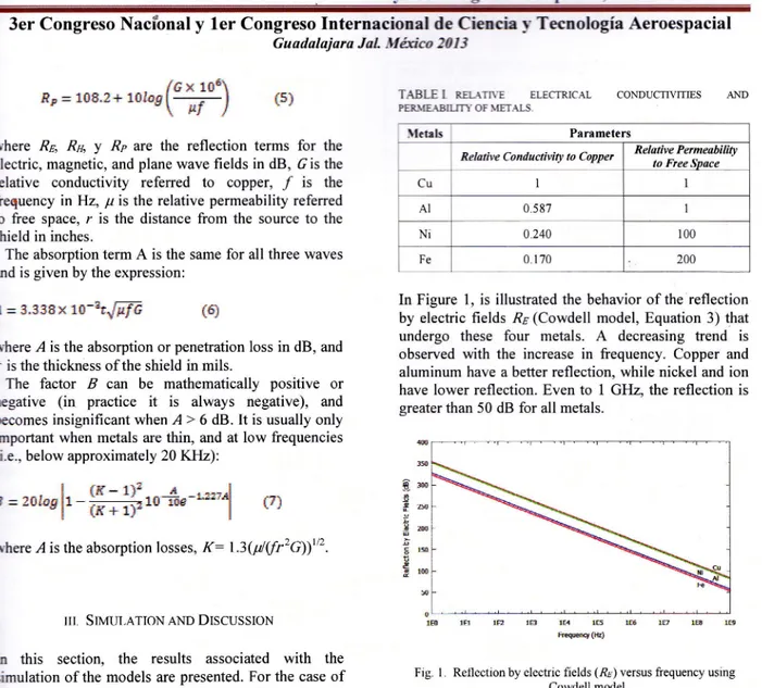
(7) & Sociedad Mexicana de Ciencia ¡'Tecnologia -{eroespacial. -\. C.. 3er Congreso Nacional y 1er Congreso Internacional de Ciencia ¡- Tecnología Aeroespacial Guadalajara JaL trI&co 2013. /t. x. 1oÉ\. Re=108.2+10loq[ . -t t¿I. T.{BLE. {5i. I. I. t R.EL{TnE ELECTRICAL. PEL\IL{BILITY. OF \fET. {I. \let¡ls. nhere R¿, Ru, y Rp are the reflection terms for the electric, magnetic, and plane wave fields in dB, 6is the relative conductivity referred to copper, / is the frequency inHz, p is the relative permeability referred to free space, r is the distance from the source to the. CONDUCTIVITIES. S,. Parameters Relative Conductivity lo Copper. Relative Permeabiliry to Ftee SDace I. Cu. AI. 0.587. I. shield in inches.. Ni. 0.240. 100. The absorption term A is the same for all three waves and is given by the expression:. Fe. 0 170. 200. á. -. r.33§H. 1,§-§r.d$f6. {q. rvhere ,4 is the absorption or penetration loss in dB, and r is the thickness of the shield in mils.. The factor ,E can be mathematically positive or negative (in practice it is always negative), and becomes insignificant when I > 6 dB. It is usually only. In Figure l, is illustrated the behavior ofthe reflection by electric fields ,R¿ (Cowdell model, Equation 3) that undergo these four metals. A decreasing trend is observed with the increase in frequency. Copper and aluminum have a better reflection, while nickel and ion have lower reflection. Even to I GHz, the reflection is greater than 50 dB for all metals.. important when metals are thin, and at low frequencies ti,e., below approximately 20 Kflz): ts. = 2olos. § r*-1\r ¡ l rojlcs-1jt-'r§ -a il. § §m I. t7j. #2s. ,Uro. where,4 is the absorption losses, K:1.3(¡t/Qir2c¡¡t/2. III.. ffi. Ers. ;I. SIMULATION AND DISCUSSION. In this section, the. results associated. with. the. simulation of the models are presented. For the case of metals, which are used in structural applications, were ñrstly simulated using Cowdell model and then using. empirical Simon formula. Flexible applications were uniquely simulated using empirical Simon formula.. .-1. StructuralMaterials F'our different metals were studied during simulation: Copper (Cu), aluminum (Al), nickel §i), and ion (Fe). -{ll effects related with electromagnetic shielding were 1 1 mil, and r srudied for/from 1 Hzto I GHz,. f:. :. inch. The data associated with electrical conductivity and permeability and used during simulations are given in Table I.. Fig.. rE1. l.. lp. r!3. lH tE5 Fr+q(e). ¡S. L*. 1tr. 18. Reflection by electric fields (flr) versus frequency using Cowdell model.. The behavior of the reflection by magnetic fields R¡r (Equation 4), it is depicted in Figure 2. To low frequencies, it is observed a decreasing trend leading even to zero reflection; for copper and aluminum between I to 10 Hz, and for nickel and iron between 1 KHz. This behavior is reverted, giving place to an in the reflection; for copper and aluminum between 10[Iz to I GHz, and for nickel and iron. to. 10. increase. between l0 KHzto. I. GHz..
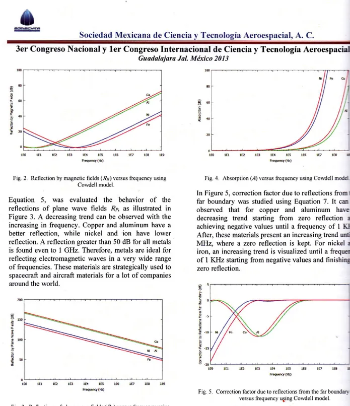
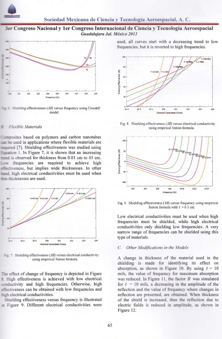
(8) ó Sociedad Mexicana de Ciencia y Tecnología Aeroespacial, A. C.. 3er Congreso Nacional y ler Congreso Internacional de Ciencia y Tecnología Aeroespaciel Guadalajaru JaL M&co 201i. 18. 1H tS k@(E). LA. Fig. 2. Reflection by magnetic fields (Rr) versus frequency using Cowdell model.. Fig.. IE. 18. lE. (,4) versus frequency using Cowdell. modd. In Figure 5, correction factor due to reflections from far boundary was studied using Equation 7. It ca. behavior of the reflections of plane wave fields R¿ as illustrated in Equation. 4. Absorption. 1H t@(k). 5, was evaluated the. observed that. Figure 3. A decreasing trend can be observed with the increasing in frequency. Copper and aluminum have a. for. copper and aluminum haw. decreasing trend starting from zero reflection achieving negative values until a frequency of I After, these materials present an increasing trend MHz, where a zero reflection is kept. For nickel iron, an increasing trend is visualized until a of I KHz starting from negative values and fini zero reflection.. better reflection, while nickel and ion have lower reflection. A reflection greater than 50 dB for all metals is found even to I GHz. Therefore, metals are ideal for reflecting electromagnetic waves in a very wide range of frequencies. These materials are strategically used to spacecraft and aircraft materials for a lot of companies around the world.. g §. 5o a-. a. E. p. a. ;m !. P. n:rú. o. -10. i(-ú. ftñ. I. a. !*. b. lB 1E5 FIw{k). 16. 10. 1B. o. ffi. [lptBlBtSlsEHlB Fwq(u). Fig. 5. Correction factor due to reflections from the far versus frequency u¡ing Cowdell model.. Fig. 3. Reflections ofplane wave fields (Rr) versus frequency using Cowdell model.. Absorption was simulated using Equation 6,. it. Shielding effectiveness is obtained adding all contributions by means of the Equation 2, and in Figure 6. Initially a decreasing trend is visualized all metals, and finishing with an increasing trend very high frequencies. Nickel and iron are the. shows. an increasing trend with the increasing of frequency as shown in Figure 4. In the cases of nickel and iron,. is presented to lower frequencies with to copper and aluminum. Aluminum has the. metals that present such reversion of behaü Therefore, it can be considered that the. absorption respect. lowest absorption with respect to the frequency of the electromagnetic wave implied, since it achieves a higher frequency with respect to others metals as is. effectiveness is presented in the frequency of l0 for nickel and iron and for copper and aluminum value is in the frequency of 100 MHz.. illustrated in Figure 4.. 64.
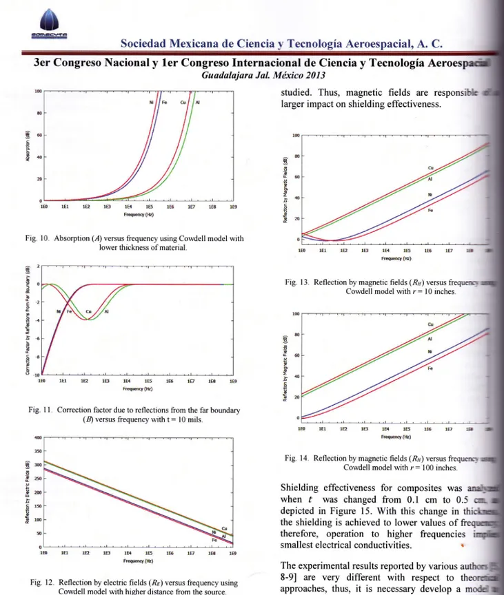
(9) o §ociedad Mexicana ele Ciencia v Tecnologia -{eroespacial. -\. C. 3er Congreso Nacional. y ler Congreso Internacional de Ciencia v Tecnología Aeroespacial Guadalajara Jal. Márico 2013. all cunes start rlith a decreasing trend to low. used.. frequencies. but it is reverted to high frequencies. { f=16 ffi. ! I ¡D. ;s. !li. ). tta,. 18. ¡H IE k€qÉq {k}. Slelding effectiveness. (.98) versus frequency using Cowdell. 1Fl. X. 1B. lFI. lF). Ektultu@ih(s/n). model.. Fig.. ,:l¿xible Materials. 8.. Shielding effectiveness (5f) versus electrical conductivrty using empirical Simon formula.. -- :rp.-sites based on polymers and carbon nanotubes mr :e used in applications where flexible materials are ,*:'-;ed [7]. Shielding effectiveness was studied using l¡iurn 1.In Figure 7, it is shown that an increasing. rqlc. ls observed for thickness from 0.01 cm to 45 cm.. fiequencies are required to achieve high *ñ:::rreness, but implies wide thicknesses. In other. -,;;. ranc-. higl electrical conductivities must be used when. ml- iricknesses are used. 16. ,o.u"*. tu.,. 1E10. Shielding effectiveness (SÉ) versus frequency using empirical Simon formula with f = 0.1 cm.. ll. Fig.. É. Low electrical conductivities must be used when high frequencies must be shielded, while high electrical conductivities only shielding low frequencies. A very narrow range of frequencies can be shielded using this. ü¡. I. 9.. lH F,wry(k). i. i i. lFl. :a-. 1B 1El EkÉlr:ffiily(s1m). type of materials.. lU. C.. Shielding effectiveness (5É) versus electrical conductivity using empirical Simon formula.. A. Other l.[odifications in the Models. change. shielding absorption.. I:e. thickness. of the material used in. its effect as shou'n in Figure 10. By using f : made. for. identifoing. the on. l0. mils, the value of fiequencl' for maximum absorption. effect ofchange offrequency is depicted in Figure t FIigh effectiveness is achieved with low electrical ::nductivity and high frequencies. Otherwise, high :it:tiveness can be obtained with low frequencies and : jr electrical conductivities. Shielding effectiveness versus frequency is illustrated. ::. in. is. was reduced. In Figure 11. the factor B was simulated for f - 10 mils. a decreasing in the amplitude of the reflection and the r alue of frequencl' rvhere changes in reflection are presented. are obtained. \\-hen thickness of the shield is increased. rhen the reflection due to electric fields is reduced in amplirude. as shoun in. Figure 9. Different electrical conductivities were. Figure. 65. 12..
(10) ó Sociedad Mexicana de Ciencia 3er Congreso Nacional y. Tecno. ial, A. C.. Aeroes. ler Congreso Internacional de Ciencia y Tecnología Guadalajara JaL Mexico 2013. studied. Thus, magnetic fields are responsiHe larger impact on shielding effectiveness.. lB. Fig. I 0. Absorption. lH ts Fryry(e). tE. (,4) versus frequency using Cowdell model. of. with. lower thickness of material.. 16. lF1. 18. lH. 185. ltr. tuqrery (u). Fig. I 3. Reflection by magnetic fields (Rr) versus frequq Cowdell model wth r = 10 inches.. EO f, fi. €+. E{ lB. lB 16 Fqmq (tE). Fig. I 1. Correction factor due to reflections from the far boundary (B) versus frequency with t = l0 mils 18. lft lEs Fqsq(k). 3S. Fig. 14. Reflection by magnetic fields (Rr) versus frequerrl Cowdell model with r = 100 inches.. 8u I. iE Eru. Shielding effectiveness. §'* pr@. s lm. f. for. composites was. was changed from 0.1 cm to 0.5 depicted in Figure 15. With this change in the shielding is achieved to lower values of therefore, operation to higher frequencies. when. lEt. lu. lB. tH. lEs. Ée*iPñq. (E). ttr. 1g. 1B. smallest electrical 1A. conductivities.. cr,. l. The experimental results reported by various 8-9] are very different with respect to approaches, thus, it is necessary develop a modd predict electromagnetic shielding including all effects offillers such as carbon. Fig. 12. Reflection by electric fields (Rr) versus frequency using Cowdell model with higher distance from the source.. A. more drastic change is observed by increasing the distance from the source to r: 10 inches (see Figure 13) or r: 100 inches (see figure 14) in the reflection. of graphene and allotropic forms of carbon as well as composites can be included. The use. on ceramics and metals will be best options to materials that develop electromagnetic shieldin-e near future.. produced by magnetic fields. For nickel and iron, a transition between decreasing and increasing trends is observed only when r -- l0 inches. Only, increasing trend is observed for r : 100 inches for all metals. 66. i¡.
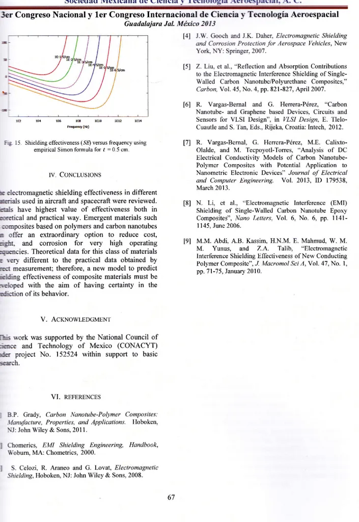
(11) G. ó Sociedad Mexicana de Ciencia y Tecnología Aeroespacial, ,4. C.. Internacional de Ciencia y Tecnología Aeroespacial -3er Congreso Nacional y ler Congreso Guadalajara JaL Mfrco 2013 t4l J-W. Gooch and J.K. Daber, Electromagnetic Shielding and Corrosion Protection for Aerospace Vehicles, New Yort- NY: Springer, 2007. t51. Z. Lfu, et al., "Reflection and Absorption Contributions to the Electromagnetic Interference Shielding of SingleWalled Carbon Nanotube/Polyurethane Composites," Carbon, Vol. 45, No. 4, pp. 821-827 , April 2007.. t6l lB Fw(e). fto. Ew. 1E14. Fig 15. Shielding effectiveness (§I) versus frequency using empirical Simon formula for. .. f. f71. = 0.5 cm.. IV. CONCLUSIONS. t8l. bretical. the. ACTNOWI-EDGMENT. sch.. REFERENCES. B.P. Grady, Carbon Nanotube-Polymer Composites: \{anufacture, Properties, and Applications. Hoboken, NJ: John Wiley & Sons, 201 l. Chomerics, EMI Shielding Engineering, Handbook, Wobum, MA: Chometrics, 2000. S. Celozi, R. Araneo and G. Lovat, Electromagnetic Shielding, Hoboken, NJ: John Wiley. &. Calixto-. N. Li, et al., "Electromagnetic Interference (EMI) Shielding of Single-Walled Carbon Nanotube Epoxy. M.. Ihb work was supported by the National Council of Ssaloce and Technology of Mexico (CONACYT) rra project No. 152524 within support to basic. FI. M.E.. Z.A.. Talib, "Electromagnetic Yunus, and Interference Shielding Effectiveness of New Conducting Polymer Composite", J. Macromol Sci A,Yol.47, No. l, pp.7l-75, January 2010.. ¡ndiction of its behavior.. trl. Henera-Pérez,. tel M.M. Abdi, A.B. Kassim, H.N.M. E. Mahmud, W. M.. operating Sgencies. Theoretical data for this class of materials G very different to the practical data obtained by &rf measurement; therefore, a new model to predict Sding effectiveness of composite materials must be. mul. G.. I 145, June 2006.. riEüt, and corrosion for very high. VI.. Vargas-Bernal,. Olalde, and M. Tecpoyotl-Torres, "Analysis of DC Electrical Conductivity Models of Carbon NanotubePolymer Composites with Potential Application to Nanometric Electronic Devices" Journal of Electrical and Computer Engineering. Vol. 2013, ID 179538,. Composites", Nano Letters, Vol. 6, No. 6, pp. 1141-. and practical way. Emergent materials such üoomposites based on polymers and carbon nanotubes r offer an extraordinary option to reduce cost,. V.. R.. March 2013.. Ih electromagnetic shielding effectiveness in different eials used in aircraft and spacecraft were reviewed. iltals have highest value of effectiveness both in. &rcbped with the aim of having certainty in. R. Vargas-Bernal and G. Herrera-Pérez, "Carbon Nanotube- and Graphene based Devices, Circuits and Sensors for VLSI Design", in VLSI Design, E. TleloCuautle and S. Tan, Eds., Rijek4 Croatia: lntech, 2012.. Sons, 2008.. 67.
(12)
Figure
+2
Documento similar
Considering the wide cultural and language differences between Spain and Mexico, the aim of this study was to test the psychometric properties of a new version of the SURPS
Dynamic performance of the ADC versus sampling frequency at F IN of 60 kHz is shown in Fig. For low sampling frequencies, the SNDR remains close to 60 dB and it shows a
For the development of the nanocomposite created, different materials were used which were characterized by different techniques to have a solid base from where to start and where
In this guide for teachers and education staff we unpack the concept of loneliness; what it is, the different types of loneliness, and explore some ways to support ourselves
No obstante, como esta enfermedad afecta a cada persona de manera diferente, no todas las opciones de cuidado y tratamiento pueden ser apropiadas para cada individuo.. La forma
The objective of this study is to carry out a descriptive analysis in order to define and understand the concept of corporate social impact and analyze different methodologies
The aim of this study is to carry out the process of translation and adaptation to Spanish of the locus of control in sport’s scale for children (Tsai and Hsieh, 2015) and to
Fast computation of shielding effectiveness of metallic enclosures with apertures and inner elements
There is an optimum for resonance damping and is the same for emission and radiation as reciprocal values of shielding effectiveness have been obtained for immunity and
