EC 1251 Guía Ohm´s And Kirchhoff´s Laws pdf
9
0
0
Texto completo
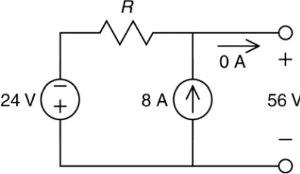
(2) Solution: Figure 2 shows the circuit from Figure 1 after replacing the voltmeter by an equivalent open circuit and labeling the voltage measured by the voltmeter. Label the element currents and voltages as shown in Figure 3. In anticipation of using Ohm’s law, the reference directions of the resistor current and voltage have been chosen to adhere to the passive convention. Consequently, the product of the resistor current and voltage is the power absorbed by the resistor, as required. The reference direction for the voltage source current has been selected so that the voltage source current and voltage do not adhere to the passive convention. Consequently, the product of the voltage source current and voltage is the power supplied by the voltage source, as required.. Figure 2 The circuit from Figure 1 after replacing the voltmeter by an open circuit.. Figure 3 The circuit from Figure 2 after labeling the element currents and voltages. Similarly, the reference direction for the current source voltage has been selected so that the current source current and voltage do not adhere to the passive convention. Consequently, the product of the current source current and voltage is the power supplied by the current source, as required. Apply KVL to the loop consisting of the voltage source, the resistor and the open circuit that replaced to voltmeter to get vR + 56 + 24 = 0 ⇒ vR = −80 V. Apply KCL at the top node of the current source to get. 2.
(3) iR + 8 = 0 ⇒ iR = −8 A. Next, Ohm’s law gives. R=. vR −80 = = 10 Ω iR −8. The power absorbed by the resistor is iR vR = ( −8 )( −80 ) = 640 W. Apply KCL at the node that connects the voltage source and resistor to get 0 = ia + iR. ⇒ ia = −iR = 8 A. The power supplied by the voltage source is ia ( 24 ) = ( 8 )( 24 ) = 192 W. Apply KVL to the mesh consisting of the current source and the open circuit that replaced to voltmeter to get 56 − vb = 0 ⇒ vb = 56 V The power supplied by the current source is. (8 ) vb = (8 )( 56 ) = 448 W As expected, the power absorbed by the resistor is equal the sum of the powers delivered by the sources. Example 2: Consider the circuit shown in Figure 4. Find the value of the resistance, R. Find the value of the power supplied by the voltage source and the power absorbed by the resistor.. Figure 4 The circuit considered in Example 2.. 3.
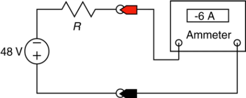
(4) Solution: Figure 5 shows the circuit from Figure 4 after replacing the ammeter by an equivalent short circuit and labeling the current measured by the ammeter. Label the element currents and voltages as shown in Figure 6. In anticipation of using Ohm’s law, the reference directions of the resistor current and voltage have been chosen to adhere to the passive convention. Consequently, the product of the resistor current and voltage is the power absorbed by the resistor, as required. The reference direction for the voltage source current has been selected so that the voltage source current and voltage do not adhere to the passive convention. Consequently, the product of the voltage source current and voltage is the power supplied by the voltage source, as required.. Figure 5 The circuit from Figure 4 after replacing the ammeter by a short circuit.. Figure 6 The circuit from Figure 5 after labeling the element currents and voltages.. Apply KVL to the mesh consisting of the voltage source, the resistor and the short circuit that replaced to ammeter to get vR + 0 + 48 = 0 ⇒ vR = −48 V. Apply KCL at the right node of the resistor to get iR = −6 ⇒ iR = −6 A. Next, Ohm’s law gives. 4.
(5) R=. vR −48 = =8 Ω iR −6. The power absorbed by the resistor is iR vR = ( −6 )( −48 ) = 288 W. Apply KCL at the node that connects the voltage source and resistor to get 0 = ia + iR. ⇒ ia = −iR = 6 A. The power supplied by the voltage source is ia ( 48 ) = ( 6 )( 48 ) = 288 W. As expected, the power absorbed by the resistor is equal the power delivered by the voltage source. Example 3: Consider the circuit shown in Figure 7. Find the value of the resistance, R. Find the value of the power supplied by each source and the power absorbed by the resistor. .. Figure 7 The circuit considered in Example 3. Solution: Figure 8 shows the circuit from Figure 7 after replacing the ammeter by an equivalent short circuit and labeling the current measured by the ammeter. Label the element currents and voltages as shown in Figure 9. In anticipation of using Ohm’s law, the reference directions of the resistor current and voltage have been chosen to adhere to the passive convention. Consequently, the product of the resistor current and voltage is the power absorbed by the resistor, as required.. 5.
(6) Figure 8 The circuit from Figure 7 after replacing the ammeter by a short circuit.. Figure 9 The circuit from Figure 8 after labeling the element currents and voltages.. The reference direction for the voltage source current has been selected so that the voltage source current and voltage do not adhere to the passive convention. Consequently, the product of the voltage source current and voltage is the power supplied by the voltage source, as required. Similarly, the reference direction for the current source voltage has been selected so that the current source current and voltage do not adhere to the passive convention. Consequently, the product of the current source current and voltage is the power supplied by the current source, as required. Apply KVL to the loop consisting of the voltage source, the resistor and the short circuit that replaced to ammeter to get vR + 0 + 12 = 0 ⇒ vR = −12 V. Apply KCL at the top node of the current source to get iR = 16 + ( −19 ) ⇒ iR = −3 A. Next, Ohm’s law gives R=. vR −12 = =4Ω iR −3. The power absorbed by the resistor is. 6.
(7) iR vR = ( −3)( −12 ) = 36 W. Apply KCL at the node that connects the voltage source and resistor to get 0 = ia + iR. ⇒ ia = −iR = 3 A. The power supplied by the voltage source is ia (12 ) = ( 3)(12 ) = 36 W. Apply KVL to the mesh consisting of the current source and the short circuit that replaced to ammeter to get 0 − vb = 0 ⇒ vb = 0 V The power supplied by the current source is. (16 ) vb = (16 )( 0 ) = 0 W As expected, the power absorbed by the resistor is equal the sum of the powers delivered by the sources. Example 4: Consider the circuit shown in Figure 10. Find the value of the resistance, R. Find the value of the power supplied by the current source and the power absorbed by the resistor.. Figure 10 The circuit considered in Example 4. Solution: Figure 11 shows the circuit from Figure 10 after replacing the voltmeter by an equivalent open circuit and labeling the voltage measured by the voltmeter. Label the element currents and voltages as shown in Figure 12. In anticipation of using Ohm’s law, the reference directions of the resistor current and voltage have been chosen to adhere to the passive convention. Consequently, the product of the resistor current and voltage is the power absorbed by the resistor, as required.. 7.
(8) The reference direction for the current source voltage has been selected so that the current source current and voltage do not adhere to the passive convention. Consequently, the product of the current source current and voltage is the power supplied by the current source, as required. Apply KVL to the mesh consisting of the resistor and the open circuit that replaced to voltmeter to get −48 − vR = 0 ⇒ vR = −48 V Apply KCL at the top node of the resistor to get 0 + iR + 4 = 0 ⇒ iR = −4 A. Next, Ohm’s law gives R=. vR −48 = = 12 Ω iR −4. The power absorbed by the resistor is iR vR = ( −4 )( −48 ) = 192 W. Apply KVL to the mesh consisting of the current source and the resistor to get vR + va = 0 ⇒ va = −vR = 48 A The power supplied by the voltage source is. ( 4 ) va = ( 4 )( 48) = 192 W As expected, the power absorbed by the resistor is equal the power delivered by the current source.. Figure 11 The circuit from Figure 10 after replacing the voltmeter by an open circuit.. 8.
(9) Figure 12 The circuit from Figure 11 after labeling the element currents and voltages.. 9.
(10)
Figure


+6


Documento similar
1. S., III, 52, 1-3: Examinadas estas cosas por nosotros, sería apropiado a los lugares antes citados tratar lo contado en la historia sobre las Amazonas que había antiguamente
Astrometric and photometric star cata- logues derived from the ESA HIPPARCOS Space Astrometry Mission.
The photometry of the 236 238 objects detected in the reference images was grouped into the reference catalog (Table 3) 5 , which contains the object identifier, the right
In the previous sections we have shown how astronomical alignments and solar hierophanies – with a common interest in the solstices − were substantiated in the
While Russian nostalgia for the late-socialism of the Brezhnev era began only after the clear-cut rupture of 1991, nostalgia for the 1970s seems to have emerged in Algeria
Peter (being copies), one sees with how much felicitousness. Jusepe de Ribera works in this way, for among al1 the great paintings the Duke of Alcalá has, [Ribera's] figures
teriza por dos factores, que vienen a determinar la especial responsabilidad que incumbe al Tribunal de Justicia en esta materia: de un lado, la inexistencia, en el
This thesis presents a body of work on the modeling of and performance predictions for carbon nanotube field-effect transistors (CNFET) and graphene field-effect transistors
