Microstructural Characterization of Multi Component Systems Produced by Mechanical Alloying
6
0
0
Texto completo
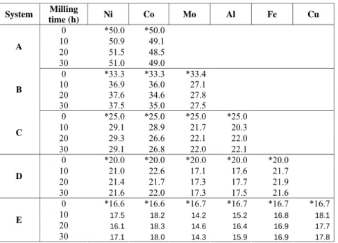
(2) supplied with an energy dispersive spectrometer (EDS), operated at 5 kV and 20 μA. They are also analyzed by X-ray diffraction (XRD) in a Siemens D5000 diffractometer with Cu Kα radiation (λ=1.5406 Å) and operated at 35 kV and 25 mA in the 2θ range of 20-110º. The step and acquisition time are 0.2º and 5 s, respectively. Table 1. Nominal* and experimental chemical compositions of different systems studied (at. %). System. A. B. C. D. E. Milling time (h) 0 10 20 30 0 10 20 30 0 10 20 30 0 10 20 30 0 10 20 30. Ni. Co. Mo. Al. Fe. Cu. *50.0 50.9 51.5 51.0 *33.3 36.9 37.6 37.5 *25.0 29.1 29.3 29.1 *20.0 21.0 21.4 21.6 *16.6. *50.0 49.1 48.5 49.0 *33.3 36.0 34.6 35.0 *25.0 28.9 26.6 26.8 *20.0 22.6 21.7 22.0 *16.6. *33.4 27.1 27.8 27.5 *25.0 21.7 22.1 22.0 *20.0 17.1 17.3 17.3 *16.7. *25.0 20.3 22.0 22.1 *20.0 17.6 17.7 17.5 *16.7. *20.0 21.7 21.9 21.6 *16.7. *16.7. 17.5 16.1 17.1. 18.2 18.3 18.0. 14.2 14.6 14.3. 15.2 16.4 15.9. 16.8 16.9 16.9. 18.1 17.7 17.8. RESULTS AND DISCUSSION Figure 1 presents the XRD spectra from binary to hexanary systems mechanically alloyed for different times. In general, elemental characteristic peaks disappear as the milling time increases while peaks corresponding to the crystallization of a single solid solution appear. For all systems, this solid solution appears from 10 h of milling time. It is important to mention that for initial powders (0 h of milling) Co has an HCP structure, which transforms to an FCC structure after the milling process due to particle size reduction and the accumulation of structural defects, as reported elsewhere [9, 10]. Thus, in figure 1a, peaks from Co HCP disappear after 10 h of milling. Ni peaks (FCC structure) are broadened and shortened as the milling time is increased; additionally the position of the Ni diffraction lines is shifted to lower angles after 10 h of milling. This displacement of the peaks remains for all milling times and it is assumed to be an indication of the formation of a FCC solid solution by MA. The XRD patterns as a function of milling time for the NiCoMo system are presented in figure 1b. Mo characteristic reflections decrease in intensity and become broader, but they are.
(3) detected even after 30 h of milling, suggesting that this element is not dissolved in Ni or Co. By comparing figures 1a and 1b, an apparent effect of Mo on the amorphous phase formation is observed; for example, in figure 1a the two first peaks of Ni –in solid solution with Co– remain even after 30 h of milling, whereas in figure 1b Ni and Co reflections become too broad or disappear after 10 h of milling. Ni Co. Ni Co Mo. 0h 10 h 20 h. Intensity (a. u.). Intensity (a. u.). a. b. 0h 10 h 20 h 30 h. 30 h. 20 30 40 50 60 70 80 90 100 110. 20 30 40 50 60 70 80 90 100 110. 2 θ (Degrees). Ni Co Mo Al Fe. c. 0h. 10 h 20 h. Intensity (a. u.). Intensity (a. u.). 2 θ (Degrees). Ni Co Mo Al. d. 0h 10 h 20 h. 30 h. 20 30 40 50 60 70 80 90 100 110. Intensity (a. u.). 2 θ (Degrees). 30 h. 20 30 40 50 60 70 80 90 100 110. Ni Co Mo Al Fe Cu. 2 θ (Degrees) e. 0h. 10 h 20 h 30 h. 20 30 40 50 60 70 80 90 100 110. 2 θ (Degrees). Figure 1. XRD spectra of the equiatomic (a) binary NiCo, (b) ternary NiCoMo,(c) quaternary NiCoMoAl, (d) quinary NiCoMoAlFe, and (e) hexanary NiCoMoAlFeCu systems as a function of milling time..
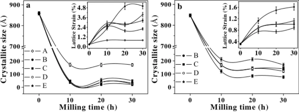
(4) 800 700. A B C D E. 200 100 0 0. 900. 4.8 3.6 2.4 1.2 0.0 0. 10. 20. 30. Lattice Strain (%). a. Crystallite size (Å). Crystallite size (Å). 900. Lattice Strain (%). Figure 1c presents XRD patterns of the NiCoMoAl alloy. In this case, 10 h of milling considerably reduce the intensity of the diffraction peaks corresponding to Ni, Co or Al. Apparently 10 and 20 h of milling induce the formation of an FCC solid solution, but a longer milling time produces an amorphous phase. Nevertheless, the XRD patterns always show Mo reflections regardless of the milling time. In this alloying system, it is appreciated a small variation of Mo peaks to higher 2θ values as the milling time increases; this denote the incipient formation of a BCC solid solution. In the case of the NiCoMoAlFe alloy, the XRD patterns are shown in figure 1d. There is a similar behavior as compared to the quaternary system. The reflections belonging to Co, Al and Fe disappear. Apparently, an amorphous phase formation is produced at long milling times while the reflections of Mo are still retained in the XRD pattern. However, in a similar case as the quaternary system, Mo reflections are shifted to higher angles as the milling time is increased, denoting the formation of a BCC solid solution. For the NiCoMoAlFeCu system (Fig. 1e), there is no evidence of Co, Al, Fe and Cu peaks even after 10 h of milling. Milling produces only short and broad peaks near the original Mo peak positions and an apparent FCC solid solution. According to the peaks position, this FCC solid solution presents higher lattice parameter than that found in the binary system (Ni-Co system, Fig. 1a). Mo characteristic reflections present shortening, broadening and shifting to higher angles denoting crystal refining and the formation of a BCC solid solution. Crystallite size and lattice strain of the alloys have been calculated from the diffraction peaks at 2θ positions near the first Ni and Mo peaks by using an algorithm included in the X’Pert Data Viewer software, based in the Scherrer formule; instrumental correction has been performed employing a silicon standard. Figure 2 shows the evolution of these parameters as a function of the milling time; each point corresponds to the average of 5 measurements and the error bars indicate the standard deviation. For all the series, a decrease in crystallite size and an increase in lattice strain are found as the milling time increases. This is attributed to the mechanical deformation introduced in the powders. Severe plastic deformation can lead to variation in crystallite size and the accumulation of internal stresses. Due to the precision achieved in our evaluations (5-15 Å), difference in crystallite size between samples B, C, D and E (Fig. 2a) could be negligible.. b. 800 700. 100 0. 10. 20. M illing time (h). 30. 0. 1.2 0.8 0.4 0. B C D E. 200. 1.6. 10. 10. 20. 20. 30. 30. M illing time (h). Figure 2. Crystallite size and lattice strain versus milling time for (a) first Ni-type and (b) first Mo-type reflections. A-E indicate the different investigated multi-component alloys..
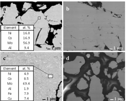
(5) Figure 3 shows the powder cross section microstructure of quaternary and hexanary alloys after 10 and 30 h of milling. For lower milling times a quasi-lamellar structure is observed, which is typical in the early stages of MA for ductile components [7]; during the SEM observations at higher magnifications, a bright phase is observed, which is identified as a Morich phase by means of EDS microanalyses (Figs. 3a and 3c). With further milling, a more uniform microstructure (Figs. 3b and 3d) is observed, but some bright particles are still noted. These results are in accordance with the XRD analysis, where Mo reflections are detected in all systems containing this element (Figs. 1b-1e). General microanalyses by EDS show that the chemical composition of all systems is homogeneous after longer milling times (Table 1); oxygen signal is not detected, indicating that the oxidation during the milling process is very low.. Figure 3. Powder cross section backscattered electron images of the quaternary NiCoMoAl alloy after (a) 10 h and (b) 30 h and the hexanary NiCoMoAlFeCu alloy after (c) 10 h and (d) 30 h of milling. From the above results, a different answer is observed in all the alloying systems studied. Binary NiCo system shows the preference to form FCC solid solution. Ternary NiCoMo system shows a sequence Crystalline Æ BCC + FCC solid solution Æ BCC + Amorphous. Quaternary NiCoMoAl and quinary NiCoMoAlFe systems show the sequence Crystalline Æ BCC solid solution + Amorphous. Finally, the hexanary NiCoMoAlFeCu system shows the preference to form a BCC + FCC solid solution. For the binary system, despite the fact that for initial powder Co presents an hexagonal structure, the final phase formed is an FCC solid solution, whose reflections correspond with Ni peaks positions. From ternary to quinary systems, the apparent amorphous phase formation after longer milling time is present. For ternary system, Mo shows.
(6) an apparent inertness to combine with Ni or Co; Mo peaks shifting is not observed. However additions of Al (quaternary system) and Al-Fe (quinary system) have an effect in the Mo peaks positions, they are shifted to higher values. Mo effect on the amorphous phase formation could be attributed to the i) atomic size factor, as reported by Miedema [11], ii) difference in crystal structure, and iii) difference in melting point. In the case of the FCC solid solution peak measurements (Fig. 2a), the presence of Mo in systems B, C, D and E induces the reduction of the crystallite size, giving rise to the formation of an apparent amorphous phase, and the increment of the lattice strain, in comparison to the NiCo system (series A). For the BCC solid solution peak measurements (Fig. 2b), the reduction of crystallite size and lattice strain increase are due just to the milling effect [7]. In both FCC and BCC solid solution peak measurements, higher values in lattice strain can be seen for the alloy system B. From figure 2b, quaternary to hexanary systems have a larger BCC solid solution crystallite size than the ternary (NiCoMo) system. The crystal size refinement and micro-tensions increment are normal answers in powder mechanically alloyed.. CONCLUSIONS The binary to hexanary equiatomic high entropy alloys in Ni-Co-Mo-Al-Fe-Cu system have been successfully synthesized by mechanical alloying in a high energy ball mill. Formation of an FCC solid solution structure after longer milling time was observed in binary and hexanary systems. After 10 h of milling, it was observed that the Mo presence improves the amorphous phase formation in ternary and quaternary systems. Mo presence favored the BCC solid solution structure formation.. ACKNOWLEDGEMENTS Thanks to W. Antúnez-Flores and E. Torres-Moye for their valuable technical assistance.. REFERENCES 1. Y. Zhang, Y.J. Zhou, X. Hui, M. Wang and G.L. Chen, Science in China Series G: Physics, Mechanics & Astronomy 51-4 (2008) 427-437. 2. Y.L. Chen, Y.H. Hu, C.W. Tsai, C.A. Hsieh, S.W. Kao, J.W. Yeh, T.S. Chin, S.K. Chen, J. Alloys Compd. 477 (2009) 696-705. 3. H. Xie, J. Lin, Y. Li, P.D. Hodgson, C. Wen, Mat. Sci. & Eng. A 459 (2007) 35-39. 4. S. Varalakshmi, M. Kamaraj, B.S. Murty, J. Alloys Compd. 460 (2008) 253-257. 5. T.K. Chen, T.T. Shun, J.W. Yeh, M.S. Wong, Surf. Coat. Technol. 188-189 (2004) 193-200. 6. C.P. Lee, Y.Y. Chen, C.Y. Hsu, J.W. Yeh and H.C. Shih, J. Electrochem. Soc. 154 (2007) C424-C430. 7. C. Suryanarayana, Progress in Materials Science 46 (2001) 1-184. 8. L. Lü and M.O. Lai, Mechanical Alloying, Kluwer Academic Publishers, Boston, 1998 9. S. Ram, Mat. Sci. & Eng. A 304-306 (2001) 923-927. 10. J.Y. Huang, Y.K. Wu and H.Q.Ye, Acta mater. 44 (1996) 1201-1209. 11. F.R. de Boer, R. Boom, W.C.M. Mattens, A.R. Miedema, A.K. Niessen, Cohesion in Metals, 2nd printing, North-Holland, New York, 1989..
(7)
Figure

Documento similar