Effect of repeated scratches on the stresses behavior in a coated system
9
0
0
Texto completo
(2) E.A. Pérez R and L.I. Negrín H. 1. INTRODUCTION In the literature is possible to found more than 20 methods to evaluate the adhesion and properties in coated systems include the indentation test, which has been the more versatile than methods such as tensile testing, due to the rapid response and the few requirements for the development of sample tests. Through this test, properties such as Elastic Modulus (E), Yield stress (σy) can be identified, up to the identification and characterization of cracking modes, hardness, and mechanical behavior in multilayer coated systems [1,2]. Other test used for the analysis of coated systems is the scratch test, which is analyzed experimentally [3-12] and by numerical simulation [13-19], to analyze the adhesion resistance and failure modes of hard coatings (HV ≥ 5 GPa) and fines (≤ 30 μm), deposited on metal substrates [20]. The test allows to establish the relationship of normal load values with the generation of failures in the coated system. The test to proves a quantitative measurement of the load necessary for the failure of a coating deposited on a ductile [8,11,12,23,24] or brittle substrate [21,22]. Likewise, it is possible to establish the failure ratio in function of the traditional test parameters such as indenter geometry, load rate, displacement rate, mechanical (elasto-plastic) properties of the materials, as well as recently with the thickness of the coating, roughness among other. According to Bull [5-7], failures on hard coating can be organized into three categories. The first category is related to cracking along the coating thickness. This failure mode occurs inside the groove and includes cracking due to tensile stresses in the back zone of contact with the indenter, cracking due to bending of the coating during scratching and Hertzian cracking. The second category is related to fragmentation, which may be due to compression or buckling of the coating, fragmentation at the front of the contact with the indenter or fragmentation at the rear of the indenter as a consequence of the portion elastic recovery. The last category is related to the chipping and detachment of the coating. This type of failure is observed in hard and thick coatings deposited on hard substrates [20]. In general, failure that occur in systems composed of hard coatings deposited on ductile materials are concentrated inside the groove of scratches during the movement of the indenter, while failures that occur in systems composed of hard coatings deposited on hard materials occur also in the lateral regions of the groove. In particular, Xie and Hawthorne [8] explain that in the case of materials with high plastic deformation, is possible to obtain high accumulation of the material in front and the edges of the contact with the indenter, in this case the surface of the system acquires high tensile stresses values as a consequence of the coating bending (Figure 1).. Figure 1 Schematic illustration of the bending induced stresses [8].. According to Bull and Berasetegui [7], the stresses generated during the movement of the indenter are complex and the literature does not present analytical models that describe exactly the types of failure that occur during scratching. For this reason, although the simulation models http://www.iaeme.com/IJMET/index.asp. 602. editor@iaeme.com.
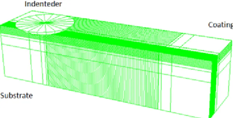
(3) Effect of Repeated Scratches on The Stresses Behavior In A Coated System. do not reproduce all the phenomena that are presented in the scratch test, they allow to obtain qualitative results based on the mechanical properties of the materials, incorporation of defects, friction forces, geometries of the bodies in contact and possibly of roughness surfaces. Using numerical analysis, Holmberg [15-18] studied the evolution of stresses during the scratch test. This is how it explains that during the first stage of the test a deformation mark is generated favoring the flow of the material towards the edges of the indenter, then the groove is generated with the respective accumulation of material in the front part of the indenter. In the lower part of the indenter plastic deformation exists and in the rear part of the same plastic deformation (Figure 2).. Figure 2 The stress field in the coated surface generated by a sliding sphere [15].. In the same way, Xiaoyu et al [24] indicate that when the indenter slides on the surface tensile stresses are created inside the groove, as well as compressive stresses in the front part of the indenter during the contact. The numerical and experimental studies of the modes of failure have been established from the realization of a single scratch. In the literature is unknown the effect of performing several cycles of scratching in a single groove, on surface failure. In this way, the principal aim of this study was to analyze, using the simulation by finite elements method, the influence of five scratch cycles in the same groove, on the behavior of longitudinal (S11) and the transversal (S33) stresses and the possible correspondence with the surface failure of the coated system. In the study was considered load normal as the principal variable for the study.. 2. MODEL SIMULATION DESCRIPTION The software ABAQUS was used to run the Finite Element Method simulations. The figure 1 shows a schematic of the geometry considered and presents the mesh used in these simulations. The simulation model considers a coated system, composed of an ideally smooth coating with characteristics of TiN deposited on a substrate with elastoplastic behavior. The totality of the property values were taken from the literature presented in previous works [15,16]. The model considers the contact of an ideally rigid particle with the geometry of a Rockwell C indenter (cone of 120° opening and radius of curvature of 200 μm at the tip), on which applies a progressive force along a scratch distance on the surface of the system covered. The simulation model is made up of 107136 hexagonal elements of eight (8) nodes for reduced integration (C3D8R) that allow the simulation through the software for analysis of elements finite ABAQUS (figure 3). In the superficial region a refinement was imposed where the thickness of the coating was divided into 10 elements, in this way each element in the contact region was established with thick of 0.2 µm. The table 1 presents the materials properties and the parameters used in the simulations.. http://www.iaeme.com/IJMET/index.asp. 603. editor@iaeme.com.
(4) E.A. Pérez R and L.I. Negrín H. Figure 3 Schematic of the geometry and the mesh used in the scratch test simulation. Table 1 Characteristics of the FEM analysis. Film E = 500 GPa, ν = 0.25, σy = 6000 MPa thickness = 2 µm Substrate E = 210 GPa, ν = 0.3, σy = 600 MPa 1mm x 0.25 mm x 0.25mm. Condition Test Normal Load 2 N, 5 N Distance scratch 0.5 mm. 3. RESULTS AND DISCUSSION Figure 4 shows the sliding direction of the indenter during the simulation of the scratch test. It also shows in detail the stress concentration in the area of contact with the indenter. In the rear area of the indenter identified as (A) the high tension values are consequence of the stretching of the material. In the below zone of the indenter identified as (B), are showed compressive stress due to the contact, finally the zone identified as (C) shows tension stress due to the coating bending for the accumulation of material during scratching.. Figure 4 Contact and sliding direction of scratch test.. Figure 5 and 6 shows the distribution of the longitudinal stress (S11) in the direction of scratching and the behavior of the transversal stress (S33) for the scratch load of 2N. The figures are obtained from a top view.. http://www.iaeme.com/IJMET/index.asp. 604. editor@iaeme.com.
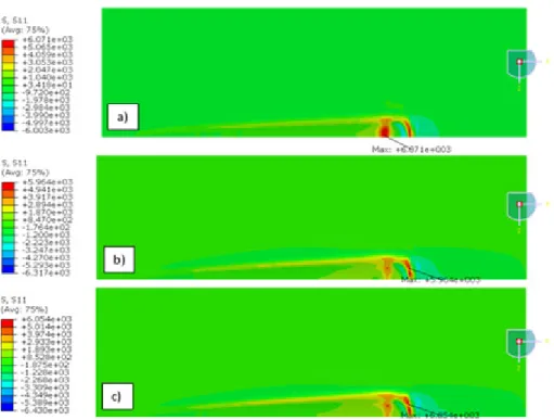
(5) Effect of Repeated Scratches on The Stresses Behavior In A Coated System. Figure 5 Longitudinal Stress (S11) map for scratch test at 2 N. a) First scratch, b) third scratch, c) fifth scratch. Figure 6 Transversal Stress (S33) map for scratch test at 2 N. a) First scratch, b) third scratch, c) fifth scratch. Figure 7 and 8 shows the distribution of the longitudinal stress (S11) in the direction of scratching and the behavior of the transversal stress (S33) for the scratch load of 5N. In the same way as the previous figures, these were obtained from a top view.. http://www.iaeme.com/IJMET/index.asp. 605. editor@iaeme.com.
(6) E.A. Pérez R and L.I. Negrín H. Figure 7 Longitudinal Stress (S11) map for scratch test at 5 N. a) First scratch, b) third scratch, c) fifth scratch. Figure 8 Longitudinal Stress (S11) map for scratch test at 5 N. a) First scratch, b) third scratch, c) fifth scratch. In the Fig. 5, is possible to observe the longitudinal stress S11 behavior, which in the first scratching cycle reaches the 6071 MPa value in the rear zone of the contact with the indenter (Figure 5a). From the second scratch cycle (Figures 5b and 5c) is observed that the highest stress values is reached in the frontal region of the indenter contact, which suggests that from the second scratching cycle the accumulation of material increases the tension stress to 6054 MPa at the fifth scratch. Regarding the behavior of the transversal stress S33, in figures 6a, 6b and 6c is possible to observe that in all the scratching cycles carried out, the resistance value. http://www.iaeme.com/IJMET/index.asp. 606. editor@iaeme.com.
(7) Effect of Repeated Scratches on The Stresses Behavior In A Coated System. imposed on the coating (6000 MPa) was exceeded. The values were reached in the region of high material accumulation (pile-up) in the frontal region of the contact with the indenter. When comparing figure 5 and figure 7 it is possible to observe that with the increase of the normal load the width of the groove in each of the lines is increased. It is also possible to observe the same behavior described in figure 5, in which during the first scratching the highest stress value in the rear region was reached on contact with the indenter. From the second scratch cycle the highest stress values were reached in the frontal region of contact with the indenter as a result of the material accumulation (pile-up). Figure 8 shows the same behavior as that described in figure 6. In this case, the stress values obtained in each scratching cycles surpassed the resistance value corresponding to the coating. In this case, is observed that as result of the increase in the normal load, the width groove was increased in comparison to the groove for 2 N load (figure 6). The results obtained are coinciding with the results of Bull [6], Bull and Berasetegui [7] and Xiaoyu et all [24]. They presented simulation results of the scratch test on a coated system composed of 2 μm TiN coating and steel substrate, indicating increased compressive stress at frontal zone of the indenter contact and tensile stress behind this. According to the Bull and Berasetegui [7], these results are probably a consequence of changes in the amount of buckling presented in the coating. In the regions of buckling (bending) around the indenter, stresses are increased as a function of the movement of the indenter. Holmberg and your research group [15-18] presents information on the cracking patterns and the coating detachment during the scratch test. A scheme of these failures can be observed in figure 9, where patterns of angular cracks (a), parallel cracks (b), semi circular cracks (c), chipping (d) and fragmentation (e and f) of the coating are presented.. Figure 9 Cracks generated in a scratch test. From the investigations Holmberg [15] identifies that the first cracks that appear during the scratch test are angular character and posterior to these the cracks of angular character arise. Finally, according to the results obtained for the simulation of a coated system composed of a ductile substrate and a hard coating and for the scratch load used, is possible to establish that the stress values S11 and S33 exceeding the resistance value are reached during the first scratch on the coating, which suggests a possible failure (cracking) of the coating inside the groove, as well as, on the side of the contact with the indenter. This suggests, unlike the results of Holberg [15], that the first crack that appears is not of angular pattern but a crack of traction inside the groove, followed by lateral cracks possibly due to the accumulation of material in the part front and side of the contact with the indenter. Likewise, the results of stresses reached (S11, S33) in subsequent scratch cycles on the same groove suggest the increase in the appearance of failures inside the groove since in some scratching cycles the highest stress values S11 are located in the groove at front region of the indenter. Likewise, it is possible to indicate that carrying out several scratch cycles on the same groove may favor the appearance of lateral cracks.. http://www.iaeme.com/IJMET/index.asp. 607. editor@iaeme.com.
(8) E.A. Pérez R and L.I. Negrín H. 4. CONCLUSION Traditionally, the numerical and experimental studies of the failure modes have been established from the realization of a single scratch. The study of several cycles of scratching on the same groove suggests that during subsequent scratching cycles the traction cracks arise inside the groove is possible. Likewise, is possible to establish that with the increase of the scratch cycles lateral cracks may still be present on the sides of the groove since, according to the model and the simulations, the stress values reached were always higher than the resistance value imposed to the coating in the simulation model.. ACKNOWLEDGEMENTS The authors recognizes the Universidad de Ibagué (Colombia) for the technical and financial support through of research project No. 18-534-INT.. REFERENCES [1]. [2]. [3] [4] [5] [6] [7]. [8]. [9]. [10]. [11]. [12] [13]. K. J. Ma, A. Bloyce, and T. Bell, “Examination of mechanical properties and failure mechanisms of TiN and Ti−TiN multilayer coatings,” Surf. Coatings Technol., vol. 76–77, pp. 297–302, 1995. M. Kot, W. Rakowski, J. M. Lackner, and Ł. Major, “Analysis of spherical indentations of coating-substrate systems: Experiments and finite element modeling,” Mater. Des., vol. 43, pp. 99–111, 2013. A. J. Perry, “Scratch adhesion testing of hard coatings,” Thin Solid Films, vol. 107, no. 2, pp. 167–180, 1983. I. Nieminen, P. Andersson, and K. Holmberg, “Friction measurement by using a scratch test method,” Wear, vol. 130, no. 1, pp. 167–178, 1989. S. J. Bull, “Failure modes in scratch adhesion testing,” Surf. Coatings Technol., vol. 50, no. 1, pp. 25–32, 1991. S. J. Bull, “Failure mode maps in the thin film scratch adhesion test,” Tribol. Int., vol. 30, no. 7, pp. 491–498, 1997. S. J. Bull and E. G.-Berasetegui, “Chapter 7 An overview of the potential of quantitative coating adhesion measurement by scratch testing,” Tribol. Interface Eng. Ser., vol. 51, pp. 136–165, 2006. Y. Xie and H. M. Hawthorne, “Effect of contact geometry on the failure modes of thin coatings in the scratch adhesion test,” Surf. Coatings Technol., vol. 155, no. 2–3, pp. 121– 129, 2002. M. Barletta, A. Gisario, G. Rubino, and L. Lusvarghi, “Influence of scratch load and speed in scratch tests of bilayer powder coatings,” Prog. Org. Coatings, vol. 64, no. 2–3, pp. 247– 258, 2009. B. D. Beake, V. M. Vishnyakov, and A. J. Harris, “Relationship between mechanical properties of thin nitride-based films and their behaviour in nano-scratch tests,” Tribol. Int., vol. 44, no. 4, pp. 468–475, 2011. M. Barletta, V. Tagliaferri, A. Gisario, and S. Venettacci, “Progressive and constant load scratch testing of single- and multi-layered composite coatings,” Tribol. Int., vol. 64, pp. 39–52, 2013. G. Pagnoux, S. Fouvry, M. Peigney, B. Delattre, and G. Mermaz-Rollet, “Influence of scratches on the wear behavior of DLC coatings,” Wear, vol. 330–331, pp. 380–389, 2014. M. Ben Tkaya, H. Zahouani, S. Mezlini, P. Kapsa, M. Zidi, and A. Dogui, “The effect of damage in the numerical simulation of a scratch test,” Wear, vol. 263, no. 7–12 SPEC. ISS., pp. 1533–1539, 2007.. http://www.iaeme.com/IJMET/index.asp. 608. editor@iaeme.com.
(9) Effect of Repeated Scratches on The Stresses Behavior In A Coated System [14]. [15]. [16]. [17]. [18]. [19] [20] [21] [22]. [23]. [24]. J. Chen and S. J. Bull, “Finite element analysis of contact induced adhesion failure in multilayer coatings with weak interfaces,” Thin Solid Films, vol. 517, no. 13, pp. 3704– 3711, 2009. A. Laukkanen, K. Holmberg, J. Koskinen, H. Ronkainen, K. Wallin, and S. Varjus, “Tribological contact analysis of a rigid ball sliding on a hard coated surface, Part III: Fracture toughness calculation and influence of residual stresses,” Surf. Coatings Technol., vol. 200, no. 12–13, pp. 3824–3844, 2006. K. Holmberg, A. Laukkanen, H. Ronkainen, K. Wallin, S. Varjus, and J. Koskinen, “Tribological contact analysis of a rigid ball sliding on a hard coated surface. Part II: Material deformations influence of coating thickness and young’s modulus,” Surf. Coatings Technol., vol. 200, no. 12–13, pp. 3810–3823, 2006. K. Holmberg, H. Ronkainen, A. Laukkanen, K. Wallin, and J. Koskinen, “Tribological analysis of TiN and DLC coated contacts by 3D FEM stress modeling and fracture toughness determination,” VTT Symp. (Valtion Tek. Tutkimuskeskus), vol. 264, no. 244, pp. 311–328, 2006. K. Holmberg, A. Laukkanen, H. Ronkainen, and K. Wallin, “Surface stresses in coated steel surfaces-influence of a bond layer on surface fracture,” Tribol. Int., vol. 42, no. 1, pp. 137– 148, 2009. P. L. Larsson, “On the correlation of scratch testing using separated elastoplastic and rigid plastic descriptions of the representative stress,” Mater. Des., vol. 43, pp. 153–160, 2013. A. Ceramics, “Standard Test Method for Adhesion Strength and Mechanical Failure Modes of,” ASTM Int., vol. C1624-05, no. Reapproved 2010, pp. 1–29, 2012. A. Favache et al., “Fracture mechanics based analysis of the scratch resistance of thin brittle coatings on a soft interlayer,” Wear, vol. 330–331, pp. 461–468, 2015. T. Sander, S. Tremmel, and S. Wartzack, “A modified scratch test for the mechanical characterization of scratch resistance and adhesion of thin hard coatings on soft substrates,” Surf. Coatings Technol., vol. 206, no. 7, pp. 1873–1878, 2011. A. Ghabchi, S. Sampath, K. Holmberg, and T. Varis, “Damage mechanisms and cracking behavior of thermal sprayed WC-CoCr coating under scratch testing,” Wear, vol. 313, no. 1–2, pp. 97–105, 2014. J. Xiaoyu, B. Lauke, and T. Schueller, “Frictional contact analysis of scratch test for elastic and elastic-plastic thin-coating/substrate materials,” Thin Solid Films, vol. 414, no. 1, pp. 63–71, 2002.. http://www.iaeme.com/IJMET/index.asp. 609. editor@iaeme.com.
(10)
Figure
![Figure 1 Schematic illustration of the bending induced stresses [8].](https://thumb-us.123doks.com/thumbv2/123dok_es/7325725.453032/2.892.292.607.827.1041/figure-schematic-illustration-bending-induced-stresses.webp)
![Figure 2 The stress field in the coated surface generated by a sliding sphere [15].](https://thumb-us.123doks.com/thumbv2/123dok_es/7325725.453032/3.892.271.624.320.529/figure-stress-field-coated-surface-generated-sliding-sphere.webp)
+2

Documento similar
The general idea of the language is to “thread together,” so to speak, existing systems that parse and analyze single web pages into a navigation procedure spanning several pages of
Government policy varies between nations and this guidance sets out the need for balanced decision-making about ways of working, and the ongoing safety considerations
No obstante, como esta enfermedad afecta a cada persona de manera diferente, no todas las opciones de cuidado y tratamiento pueden ser apropiadas para cada individuo.. La forma
La consulta d’aquesta tesi queda condicionada a l’acceptació de les següents condicions d'ús: La difusió d’aquesta tesi per mitjà del servei TDX (www.tdx.cat) ha estat
rous artworks, such as sonorou s poetry; d) instances of nOlHu1islie music, such as sonorous activiti es with soc ial, bu t not necessarily aes thetic, funct ions. Lango
On the other hand at Alalakh Level VII and at Mari, which are the sites in the Semitic world with the closest affinities to Minoan Crete, the language used was Old Babylonian,
Nevertheless, the ratio of corporations using patents of introduction is higher than that obtained from the analysis of the entire patent system as a whole (around 8.5% from 1820
What is perhaps most striking from a historical point of view is the university’s lengthy history as an exclusively male community.. The question of gender obviously has a major role
