Design and Implementation of a Technology Planar 4x4
Butler Matrix for Networks Application
M. Moubadir1, H. Aziz1, N. Amar Touhami1, M. Aghoutane1, K. Zeljami1 and A. Tazon2 1 Laboratory of Information System and Telecommunications,
Abdelmalek Essaadi University, MOROCCO 2 University of Cantabria, SPAIN E-mail: [email protected] Abstract - In this paper, switched beam smart
antenna systems are investigated to improve the performance of wireless networks. The microstrip technology of antenna arrays with Butler matrix topology as a beam-former is used to implement the switched beam smart antenna system. The optimum design of a 4x4 planar Butler matrix array, operating at 5.6 GHz for WLAN applications. System’s design and optimization was based on computer simulations.
Index Terms-Butler Matrix, Switched beam, Antenna Array.
I. INTRODUCTION
In wireless communication systems, multipath fading, delay and interference occurred by reflection or diffraction. In a high-speed wireless communication, it becomes a necessary to separate desired signal from delay or interference signal. Thus to overcome these problems, smart antenna systems have been developed.
Now Smart antenna [1] is one of the most promising technologies that will enable a higher capacity in wireless networks by effectively reducing multipath and channel interference. This is achieved by focusing the radiation only in the desired direction and adjusting itself to changing traffic conditions or signal environments. Smart antennas employ a set of radiating elements arranged in the form of an array.
The 4x4 planar Butler matrix array [2-4] is a key component of the switched beam system. Basically this Butler matrix array forms multiple fixed overlapping beams which will cover the designated angular area. It is a NxN passive
feeding network with N radiating elements. The output ports of the butler matrix feed the antenna elements. It is easy to implement and requires few components to build compared to the other networks. The loss involved is very small, which comes from the insertion loss in hybrids, phase shifters and transmission lines. However in a butler matrix, beam width and bean angles tend to vary with frequency. Also it has a complex interconnection scheme for a large matrix. Butler matrix [5] has been implemented with various techniques such as waveguide, microstrip, multilayer microstrip, suspended strip line, CPW etc. Microstrip technique is widely used in Butler matrix due to its numerous advantages such as low profile, easy fabrication and low cost.
In this paper we use the microstrip technique [6-7] to implement the Butler matrix array. The major components of the Butler matrix such as hybrid couplers, crossovers and phase shifters are designed by microstrip line technique and the array is formed by four rectangular patch microstrip antennas with inset feeding.
II. BEAMFORMING NETWORK
Switched beam systems [2] are referred as antenna-array systems that form multiple-fixed beams [3-4] with enhanced sensitivity in a specific area. This antenna system detects signal strength, selects one of the several predetermined fixed beams, and switches from one beam to another as the user moves. Like the switched-beam antenna array presented here in Figure 1.
Fig.1. The geometry and the desired beam-set of a four-element phased array.
Referring to the geometry of Figure 1, let us assume a 4-element linear array with identical elements and identical magnitude excitation. Furthermore all elements are equally spaced with distance d and each element has
𝛥𝜙
current progressive phase excitation, relative to the preceding one.Assuming that the reference point is the physical center of the array, the normalized array factor AF (Ψ) of the above geometry can be expressed as [8][9]:
|𝐸
𝑟| =
𝐸0𝐼0 𝑟 𝑠𝑖𝑛(𝑁𝜓2 ) 𝑠𝑖𝑛(𝜓2)(1)
with:𝛹 = 𝑘𝑑 𝑐𝑜𝑠(𝜃) + 𝛥𝜙
(2)
The Array Factor:𝐴𝐹 =
1𝑁 𝑠𝑖𝑛(𝑁𝜓2 ) 𝑠𝑖𝑛(𝜓2)
(3)
𝐴𝐹(𝛹) =
1 4×
𝑠𝑖𝑛(2𝛹) 𝑠𝑖𝑛(𝜓2)(4)
The array factor of (4) is function of the current progressive phase excitation
𝛥𝜙
𝑖 [10]:𝜃
𝑖= 𝑐𝑜𝑠
−1(
𝜆𝛥𝜙𝑖2𝜋𝑑
)
(5)
III. BUTLER MATRIX
The Butler matrix has four inputs and four outputs, and it is implemented to excite an array of four patch radiating elements to produce four beams in desired directions. Figure 2 shows the general block structure of a Butler matrix [2]. The design of a Butler matrix 4x4 need four hybrid couplers (3dB, 90°) and two equal fixed phase shifters (-45) and two crossover that can replace each by two hybrid junctions (3dB 90°) placed end to end, also called a coupler 0dB. We will use this topology with an array of four antennas per unit length radiating elements.
Fig.2. Block diagram of 4x4 Butler matrix array.
A. Hybrid (3 dB, 90°)
Hybrid coupler is well known devices used for their ability to produce 90° phase shifted signals to these outputs [11]. The associated S matrix of this element has the following form:
𝑺 =−𝟏 √𝟐[ 𝟎 𝟎 𝟎 𝟎 𝟏 𝒋 𝒋 𝟏 𝟏 𝒋 𝒋 𝟏 𝟎 𝟎 𝟎 𝟎 ]
(6)
P1 input power is divided into two output signals P3 (direct route) and P4 (coupled channel). Port 2 is isolated with respect to the input. The phase difference between the output ports is 90° [12], this phase shift is independent of the coupling.
B. Phase shifter:
The phase shifter use the transmission lines to phase delay [14][6]. So, to create a phase delay θ with a microstrip line over another, just add an extra length of line:
∆L = θ. λg/360 (7)
Fig.4. Phase shifter.
C. Crossover:
In a 4x4 Butler matrix, there are two crossovers. By cascading two hybrid couplers, you can implement a crossover, also called a coupler 0 dB (Figure 5).
Fig.5. Crossover.
The associated S matrix of this element has the following form: 𝑺 = [ 𝟎 𝟎 𝟎 𝟎 𝟎 𝒋 𝒋 𝟎 𝟎 𝒋 𝒋 𝟎 𝟎 𝟎 𝟎 𝟎 ]
(8)
IV. IMPLEMENTATION OF 4x4 BUTLER MATRIX:
The Butler matrix is a type of beam-forming network. Depending on which of N inputs is accessed, the antenna beam is steered in a specific direction (Figure 1). The microstrip technique is used for the implementation of the matrix, there are several cross lines and crossovers to isolate the signal [14].
The Table 1 shows the summary of the corresponding magnitudes and phase shifts between the inputs and the outputs of the Butler matrix.
Table 1:Magnitudes and phase shifts at the inputs and outputs of Butler matrix.
The Butler matrix is implemented to excite an array of four patch radiating elements to produce four beams in desired directions. The operating frequency is around 5.6 GHz.
V. DESIGN OF ARRAYS ANTENNA:
A. Patch antenna:
The proposed microstrip patch antenna is shown in Figure 6. In this design the substrate FR4 is used due to its low cost and easy fabrication. The substrate height is 0.76 mm, the dielectric constant is 3.2 and the loss tangent is 0.035. The dimensions of our antenna are optimized by using electromagnetic software.
Fig.6. Top view of our patch antenna resonating at 5.6 GHz. (Wp = 18.73 mm, Lp = 14.475 mm, We =1.04 mm, Le = 4.864 mm, Wq = 1.83 mm, Lq = 16.864 mm).
Figure 7 presents the scattering parameter of the patch antenna operating at 5.6 GHz. We can see that the adaptation is better than 30dB.
Figure 8 shows the radiation pattern of the antenna. The gain of the antenna is around 6dB in the resonance frequency.
Fig.7. Parameter S11 of a patch antenna.
Fig.8. Radiation pattern of a patch antenna in 3D.
B. Array antenna:
Figure 9 shows the array of four patches, the distance between the patches elements is around 0.7𝜆 [8][15]. Figure 10 presents the scattering parameters of the array antenna. We can see that the return loss is better than 30dB and the isolation between the array elements is better than 25dB in the operating frequency.
The radiation pattern of the antenna array is presented in Figure 11, the gain of the array is increased of 6dB and the radiation direction is broadside.
Fig.9. Design of array antenna network.
Fig.10. Simulation of scattering parameters of array antenna.
Fig.11. Radiation pattern of a patch antenna array in 3D.
VI. ANTENNA ARRAY WITH BEAMFORMING NETWORK:
The final layout of the optimized antenna with its beamforming network is shown in Figure 12. Beamforming characteristics of the proposed smart antenna system are obtained for uniform amplitude distribution [9][16].
Fig. 12. Final layout of the proposed antenna array with its beamforming network.
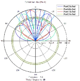
2-D polar far field patterns are obtained and plotted in Figures 13 and 14 which achieve the targeted specifications. From the radiation patterns, it is shown that the angles of the four beams associated with different inputs are 30, 15, -15, and -30. We can see that the theoretical results agree well with the simulation results.
Fig.13. Calculated beam patterns at 5.6 GHz when port 1, 2, 3 and 4 are fed.
Fig.14. Simulated beam patterns at 5.6 GHz when port 1, 2, 3 and 4 are fed.
VII. CONCLUSION
This paper presents a planar implementation of a smart antenna system using microstrip antenna array with Butler beamforming network for wireless applications. A linear antenna array is initially designed and optimized using Electromagnitique software.
The Beamforming/feeder network is designed using a 4x4 Butler matrix, and realized using 4 quadrature hybrids, 2 phase shifters and 2 crossover circuits. The microstrip antenna array and the Butler matrix feed network are simulated and optimized to achieve the required radiation characteristics. The comparison between the theoretical and simulation radiation pattern shows a good agreement.
ACKNOWLEDGMENT
The authors would like to thank the department of engineering of communications, University of Cantabria.
REFERENCES
[1] J. Winters, “Smart antennas for wireless systems,” IEEE Personal Communications, pp. 23-27, Feb. 1998.
[2] I. Siti Zuraidah, M. Kamal A.Rahim, “Switched beam antenna using omnidirectional antenna array”, Asia-Pacific Conference on Applied Electromagnetics Proceedings, Malaysia, 2007. [3] A. Siti Rohaini, F. Che Seman, “4-port Butler
matrix for switched multibeam antenna array” IEEE, Asia-Pacific Conference on Applied Electromagnetics Proceedings, Johor, Malaysia, Dec. 20-21, 2005.
[4] D.C. Chang, S.H. Jou, “The study of Butler matrix BFN for four beams antenna system”, IEEE Antenna and Propagation Society International Symposium, Vol. 4, pp. 176-179, 2003.
[5] C. Dall’omo, “Contribution à l’étude d’antennes à pointage électronique en millimétrique. Conception et réalisation de différentes topologies de Matrices de Butler.” Thèse de doctorat n° 42-2003, U.E.R. des Sciences, Université de Limoges, Nov. 2003.
[6] D.M. Pozar, “Microwave engineering”, Third edition, Wiley, 2005.
[7] E.H Fooks, “Microwave engineering using microstrip circuits”, Prentice Hall, New York, USA, 1990.
[8] C.A. Balanis, Antenna Theory, Analysis and Design, 2nd ed., Wiley, 1997.
[9] S.Z. Ibrahim, “Design of multibeam antenna for wireless local area network application”, Universiti Teknologi Malaysia: M.Eng. Thesis, Malaysia, 2007.
[10] C.A. Balanis Antenna Theory. 3rd ed. Hoboken, N.
J: John Wiley & Sons. 2005.
[11] H.J. Moody, “The systematic design of the Butler matrix,” IEEE Transactions on Antennas and Propagation, Vol. 12, Issue 6, pp. 786-788. Nov. 1964.
[12] C. Chi, G. Rebeiz, “Design of lange couplers and single side band misers using micromachining techniques”. IEEE Trans. On microwave theory and techniques, Vol. 45, No. 2, Feb. 1997. [13] A. Angelucci, P. Audagnotto, P. Corda, P. Obino,
F. Piarulli, “High performance microstrip networks for multibeam and reconfigurable operation in mobile-radio systems” Proc. IEEE GLOBECOM'94, San Francisco, USA, Nov. 1994. [14] Wight, J S., W. J. Chudobiak, “The micro-strip and stripline crossover structure” IEEE trans. On microwave theory and techniques, p-270, May 1976.
[15] Denidni, A. Tayeb, T.E. Libar, “Experimental investigation of a microstrip planar feeding network for a switched-beam antenna array”. IEEE Antennas and Propagation Society International Symposium, 1: 130-133. 2002. [16] Salvatore, B.C., A. Balanis, F. Jeffrey, S.A.
Spanias. “Smart antenna systems for mobile communication networks, part 1: overview and antenna design”. IEEE Antenna’s and Propagation Magazine, 44(3): 145-154. 2002.