Evaluation of Using Semi-Autonomy Features in Mobile Robotic
Telepresence Systems
Andrey Kiselev, Annica Kristoffersson, Francisco Melendez,
Cipriano Galindo, Amy Loutfi, Javier Gonzalez-Jimenez, Silvia Coradeschi
Abstract— Mobile robotic telepresence systems used for social interaction scenarios require that users steer robots in a remote environment. As a consequence, a heavy workload can be put on users if they are unfamiliar with using robotic telepresence units. One way to lessen this workload is to automate certain operations performed during a telepresence session in order to assist remote drivers in navigating the robot in new environ-ments. Such operations include autonomous robot localization and navigation to certain points in the home and automatic docking of the robot to the charging station. In this paper we describe the implementation of such autonomous features along with user evaluation study. The evaluation scenario is focused on the first experience on using the system by novice users. Importantly, that the scenario taken in this study assumed that participants have as little as possible prior information about the system. Four different use-cases were identified from the user behaviour analysis.
I. INTRODUCTION
Robotic telepresence, also known as telerobotics is a subfield of telepresence whose aim is to provide remote presence via embodiment in a robotic platform. In particular, robotic telepresence can be an effective tool to enhance social interaction suited to certain groups of users. One such group is the elderly who can benefit from robotic telepresence to receive visits of relatives and caregivers. In this case, the telepresence robot can be installed in the elderly home to allow caregivers to connect more frequently from remote locations [1], [2]. This type of application domain has been the focus of a number of works [3], [4], [5]. However, as pointed out by these studies, real use of telepresence systems for promoting social interaction for elderly at home often implies user groups (on both ends) that are novice users of telepresence and robotic devices. Consequently, the quality of social interaction between people may be hindered by a technology perceived as difficult to use or operate. In fact, previous studies have shown that a high mental workload has been associated to remote driving of telepresence units [6]. One method to mitigate this workload has been to add a number of autonomous features to telepresence robots [7], [8]. These features simplify certain tasks, such as navigating to specified rooms or docking the robot to the charging
Andrey Kiselev, Annica Kristoffersson, Amy Loutfi, Silvia Corade-schi are with the Centre for Applied Autonomous Sensor Systems,
¨
Orebro University, ¨Orebro, Sweden, (e-mail: [email protected], [email protected], [email protected])
Francisco Melendez, Cipriano Galindo, Javier Gonzalez-Jimenez are with System Engineering and Automation Department, University of Malaga, Malaga, Spain, (e-mail: [email protected], [email protected], [email protected])
station. These tasks have been identified in previous work as particularly challenging for novice users [9], [10].
The inclusion of semi-autonomous abilities to assistant or service robots that perform within human environments becomes a necessity for certain applications. In the particular case where the human is involved in the control loop, as it is in our case, semi-autonomous navigation allows the user to concentrate on different tasks rather than on the teleoperation of the robot itself [11], [12], [13]. For example, endowing a MRP system with semi-autonomous navigation relieves the pilot user to carry out tedious or difficult maneuvers, like following a corridor or crossing a doorway, while concentrating attention to the interaction with the local user. In this paper we present the implementation of several autonomous features for a specific telepresence robot. The features include autonomous mapping and local-ization, navigation to given points in the environment and automatic docking to a charging station. The robot used is a Giraff platforms which is a differential drive robot, equipped with screen, camera, speaker and microphone and has been previously used in a number of studies [14], [15], [16].
The paper is organized as follows: Section II provides a detailed description of the implemented system; method of experiment is shown in Section III and results – in Section IV. The paper is concluded by Section V.
II. SYSTEM DESCRIPTION
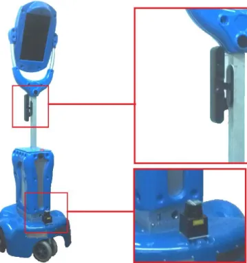
The MRP system used in this work is based on the Giraff robot [17] (Fig. 1a). In previous works, the performance of this robot has been enhanced to automatically avoid obstacles in its surroundings, provide an accurate and real-time estima-tion of its posiestima-tion, and to carry out autonomous navigaestima-tion [18]. To enable these operations, the hardware of the Giraff has been complemented with a Hokuyo laser scanner [19] for 2D localization, and a RGBD camera [20] for 3D obstacle avoidance. Moreover, the onboard camera of the robot is used for automatic docking maneuvers, a standard feature of the software provided by Giraff Technologies AB.
A. System setup
In order to provide the semi-autonomous navigation fea-tures to the enhanced MRP system, some setup steps are needed. Concretely, (i) ageometrical mapof the environment has to be generated for robot self-localization purposes, and (ii) a topological map, i.e. a set of interconnected distinc-tive places, has to be defined for user-friendly navigation. For the former, a technician guides the robot covering the
7th IEEE International Conference on
Fig. 1. The Giraff MRP system with the additional sensors: Hokuyo laser scanner and Primesense RGB-D sensor.
environment while the system collects and stores the robot odometry and the measurements from the laser scanner. This information is off-lined processed to create a point-based geometrical map through the Iterative Close Point
(ICP) algorithm [21]. For the sake of user visualization, this map can be enriched with graphical elements to produce a schematic map, that depicts, for instance, walls, doors, furniture, etc. (see figure 2).
Once the geometrical map is constructed the user can select a number of distinctive places of his interest for future navigation. Thus, a topological map is created by clicking the location of the selected places on the geometrical map. The result is a graph where nodes are annotated with the geometrical positions of distinctive places, some of them labelled with friendly names, e.g. corridor, kitchen, etc., and the arcs indicate the possibility of navigating from one place to another. Both, the geometrical and the topological maps can be created and edited through the semi-autonomous plugin described in the next section. More details can be consulted in [18].
After the setup, the user can interface with the MRP system through the client interface (see figure 3) in different manners:
• Manual driving. The user can drive the robot via the original interface provided by Giraff AB. That is, s/he can mark a point on the camera image which is related to the robot reference frame, issuing the proper motors’ consigns.
• Autonomous driving. The user can select one of the predefined destinations from the topological map as the destination of the robot navigation. During the operation
Fig. 2. From left to right, the geometrical, topological, and schematic maps of the test environment, embedded into the implemented plugin. Only the later one is shown to the subjects of our evaluation.
main view
drive plugin setting
s
Fig. 3. Client interface of the Giraff MRP system. The semi-autonomous navigation plugin is on the left, highlighted in red.
the user can stop the robot motion immediately by just clicking on the interface.
• System information. At any time, the user is graphically informed about the current location of the robot and the risk of collisions. For the later, red indicators are shown around the robot icon in the direction of near obstacles, i.e. detected closer than 30 cm.
Advanced features can be accessed for granted users (not considered in this paper), enabling them to modify the topological map, visualize low-level sensor data, etc.
B. Software architecture
The software architecture that manages the MRP system and the semi-autonomous navigation functionality is divided into two parts:
• The client interface that runs on the user’s computer (see Fig. 3). It provides an intuitive GUI that permits users to command the robot and conveniently visualize information from the remote environment.
reac-tive navigation and localization algorithms, and provid-ing information to the client interface.
In the following more details about these software com-ponents are given.
C. Client interface
The client interface consists of the original teleopera-tion applicateleopera-tion (Giraff Pilot) enhanced with a specifically designed plugin that improves the remote robot driving with semi-autonomous navigation. This plugin comprises the following elements (see Fig. 3):
1) A dropdown menu with the available destinations to which the robot can navigate autonomously. The list contains the labels of the topological map previously created, e.g. corridor, bedroom, etc., enabling the driver to intuitively command the robot. As commented, only granted users can add/remove/rename the list of distinc-tive places for navigation.
2) The schematic map of the robot environment on which its current position is displayed and continuously up-dated. This map is an idealization of the environment constructed upon the geometrical map managed by the robot.
3) Visualization options, e.g. centering the map view with respect to the robot position or scrolling it.
Through the implemented plugin, the user can issue au-tonomous navigation commands by selecting the desired destination either by selecting the label from the dropdown menu or by clicking directly on the label shown on the schematic map. The user can monitor the progress of the navigation by checking the position of the robot within the map. Although the system is highly robust, changes in the environment may cause localization failures. This situation can be easily noticed by the user since the position shown on the map does not correspond to the visual information coming from the robot webcam. In these cases, the driver can reset the robot localization system and establish a new location based on the current information and his knowledge about the environment. It is important to remark that these localization errors do not jeopardize the security of the system since the low-level obstacle detection process stops the robot in case of imminent collisions.
D. Robot control architecture
The control architecture that manages the robotic system relies onOpenMORA[22], an implementation of the hybrid architectureACRHIN[23] with proven suitability for service robots [24]. The particular implementation used in this work is based on the MRPT framework [25] and on MOOS [26], a TCP-based middleware that implements a centralized black-board where the modules share information. The communi-cation with the client interface has been implemented using theMQTT protocol [27].
The robotic modules that constitute the control architecture can be divided into two groups: low-level modules which provide basic access to sensors and actuators, and high-level
modules which process sensorial information and are directly involved in the localization, and navigation operations.
The low level modules are:
a) Motors’ controller: This module is in charge of managing and setting the corresponding motor signals, as well as of reading the encoder-based odometry of the robot. It accepts motion commands from two separated sources: (i) from the user’s manual driving and (ii) from the reactive navigator as a sequence of motion commands to reach a given destination. It is important to remark that both sources are treated separately and that the current implementation does not combine them.
b) Laser scanner manager: It continuously collects and publishes scans from the laser on the blackboard. High-level modules, e.g. robot localization, can access to the laser data at15Hzwhich suffices for our application.
c) RGBD camera manager: It preprocesses and pub-lishes 3D point clouds on the blackboard. The dense clouds provided by the RGBD camera are decimated by projecting the 3D data into a number of 2D planes that only account for the closest obstacles at a number of heights. The processed point clouds are then properly managed by the reactive navigator which accounts for the particular 3D shape of the robot and identify any possible risk of collision (see figure 4).
The high-level modules involved in our experiments are:
d) Robot localization: Giraff self-localization relies on the well-known particle filter techniques [28] to estimate the pose (position and orientation) of the robot with respect to the generated geometrical map. In a nutshell the algorithm considers a set of pose hypotheses which are iteratively re-inforced or discarded according to the perceived information (scans), and propagated to a new localization following the robot odometry information. In case the solution does not converge the algorithm selects a new set of hypothesis around the last robot position or it can be reset by the user who can establish a new localization area through the “relocalize” button on the client interface.
e) Reactive navigator: It computes a sequence of mo-tors’ commands to safely perform a local navigation from the robot’s current position to a nearby one. We rely on a 3D reactive navigational approach that takes into account both the actual 3D shape of the robot and the 3D surrounding obstacles. For that, the robot volume is modeled by a number of consecutive prisms in height and the detected obstacles are segmented into these heights (see figure 4). Then, the reactive navigation problem is tackled by a number of concurrent 2D navigators, one per prism, which are consistently and efficiently combined to yield an overall solution. More details can be consulted in [29].
f) Global path planner: It complements the work of the reactive navigator but focuses on the navigation to distant destinations, i.e. global navigation. This module runs anA∗
Fig. 4. Obstacles are sorted in height bands according to the robot height sections.
sequentially guides the robot to each intermediate node of the found path until the final destination is reached.
III. EVALUATION
In this study we take a look at the first users’ attempt to use the system. As a basis of this study, we take the scenario when the MRP system is used for the first time and users have very limited knowledge of its functionality and basic principles of operation. This situations when users do not read manuals thoroughly before they use the system is common and discussed by [30].
The objective of this study is to analyse how the robot autonomy functionality can be used by novice users. Thus, in this study, we put the focus primarily on users’ driving experience. In the experiment we analyse the system as a whole. Our goal is to observe if the autonomy features of the system can be found on user interface, how they can be used, and if they make any significant impact on task completion.
In this study, we use mouse tracking data and use UI heatmaps as visual representation to analyse the data. The task for the subjects in our experiment is to connect remotely to a lab facility, perform a regular laboratory condition check-up, check four gauges in different location, fill the data into a form and put the robot to the charging station.
In this experiment, the Giraff robot was located in Malaga, Spain and participants were connecting from ¨Orebro, Swe-den. The map of the lab facility is shown on Fig. 5. During the experiments the lab kept its normal use, where around 10 students was working every day. Fourteen participants (6 women and 8 men) were recruited at School of Science and Technology, ¨Orebro university, Sweden. The participants (administrators, students and teachers) age varied between 20 and 54 (µ = 33.40, σ = 10.16). Half of them had real-life experience of robots and all but two play video-games occasionally or often. All participants visited the environment while maneuvering a MRP system for the first time. None of subjects have prior experience with using the Giraff system.
Fig. 5. Map of the robot’s environment. It is composed of two connected rooms and a corridor with a total area of 100 square meters. The cyan triangle indicates the position of the recharging station.
While many users try new internet communication (ICT) technologies without opening the manual, it could be ex-pected that users needed a short introduction into how the application could be used prior to the first use. Therefore, the participants were advised to read a short four-page manual prior to their participation in the experiment, however this was not obligatory. The manual contained an image depicting the different panels available within the graphical user interface (Pilot + semi-autonomous plugin), information about what means could be used for maneuvering the robot and how to autonomously dock the robot into the docking station.
IV. RESULTS
A. Visualization
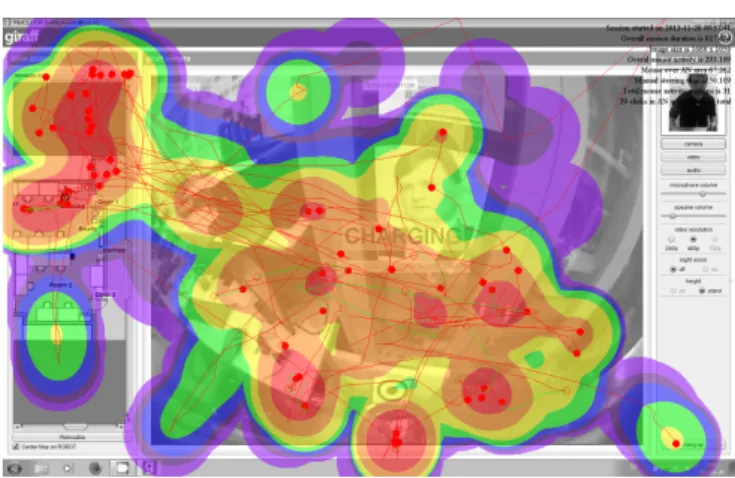
In this study, heatmaps of mouse tracking data are used to identify different usage scenarios and highlight the most and least used features on user interface.
The method to build heatmaps is following the standard for usability testing. The values of all points are normalized on a logarithmic scale from0toe7. The heatmap color scheme is as follows: 0...e1 – violet; e1...e2 – indigo; e2...e3 – blue; e3...e4 – green; e4...e5 – yellow; e5...e6 – orange;
e6...e7 – red.
The logarithmic scale was used to obtain better granularity of the results. In addition to heatmap data, raw trajectories were put onto the graphs. There are two colors of trajecto-ries: red trajectory represents normal mouse movements and green trajectory represents mouse movements during manual steering. Circles shows mouse button press events.
Fig. 6. Fully manual driving session.
Fig. 7. Driving session using autonomy features extensively.
manual driving session (Fig. 6); i) driving session fully rely-ing on usage of autonomy features (Fig. 7); i) combination of manual and autonomous driving (Fig. 8). All three driving session are real session of subjects.
Heatmap on Fig. 7 shows that highest attention was paid to the top part of the map area and a dropdown menu, but other area were also visited. Contrary, in manual mode (Fig. 6) all attention was concentrated in the central area of the video, where the actual driving is done and other area were not visited at all. Additional statistical analysis of manual sessions also shown much higher mouse activity, which may potentially result in higher burden. Driving sessions where both methods were combined (Fig. 8) also reveal that all panels are covered (like in autonavigation mode), but most attention is still concentrated in a driving area.
The use of the autonomous docking feature was analysed by watching the video recordings. Eleven succeeded to use the method outlined in the manual while two participants docked manually.
B. Analysis
The use of autonomy features was estimated by calculating the number of clicks in the drive plugin area and comparing it with the number of clicks overall. Additionally to that, video analysis was used in order to identify different
sce-Fig. 8. Driving session performed using a combination of the two driving methods.
narios when autonomy features were used or not used. Such scenarios were:
• autonomy features were not used at all;
• autonomy features were used in the beginning and then participant switch to manual mode;
• autonomy features were used in the end;
• task was accomplished entirely in autonomous mode. From the data, it was found that two participants con-ducted the task using semi-autonomy features throughout. These two participants consistently made use of the drop-down menu to select the desired destination. One partici-pant drove manually in the beginning of the session, but after experiencing some problems with manual steering, the person chose to use the map for the remainder of the task. Two participants drove manually from the beginning and then used the dropdown menu to reach Door2. From this point, they maneuvered the robot manually. Notable for these two participants is that they used sliders to orient the map to see
Door1but then chose the desired location from the dropdown menu. Other subjects completed the task entirely in manual operation mode, however, we cannot claim that localization features were not used since no gaze tracking analysis was done.
V. DISCUSSION AND CONCLUSIONS
Several studies have previously outlined a need to include semi-autonomous features in mobile robotic telepresence (MRP) systems in order to aid the pilot users in maneuvering the robots. In this paper, we have described an imple-mentation of semi-autonomy for the MRP system Giraff. The implementation includes a semi-autonomy plugin which allows pilot users to specify desired destinations for the robot by clicking on labels on a map or in a dropdown list. The implementation also features semi-autonomous docking and the standard manual driving plugin.
during their first encounter, we can see that most participants maneuvered the robot manually. Six of these never clicked in the semi-autonomous plugin while six clicked a few times (up to 10%). Two participants clearly made use of the semi-autonomous plugin.
In this work a number of techniques for evaluating auton-omy functions were used. The main goal of this study was to look at the situation when a complex device for controlling a remote robot is used for the first time with no prior training. The results of this study can lead to important insights for Quality of Live technologies as they show how novice users can cope with advanced technologies at homes.
ACKNOWLEDGMENT
This work has been made possible through the financial support by Ambient Assisted Living Joint Program ExCITE Project (AAL-2009-2-125) and “TAROTH: New develop-ments toward a robot at home”, funded by the Spanish Gov. under contract DPI2011-25483.
REFERENCES
[1] P. Boissy, H. Corriveau, F. Michaud, D. Labont´e, and M.-P. Royer, “A qualitative study of in-home robotic telepresence for home care of community-living elderly subjects.” Journal of telemedicine and telecare, vol. 13, no. 2, pp. 79–84, 2007.
[2] K. Scheepmans, B. C. Dierckx, L. Paquay, and K. Milisen, “Restraint use in home care: A qualitative study about the experiences of home care nurses,”European Geriatric Medicine, vol. 3, 2012.
[3] A. Kiselev, A. Kristoffersson, and A. Loutfi, “The effect of the field of view in mobile robotic telepresence systems on social interaction,” inProceedings of the HRI 2014, 2014, pp. 214–215.
[4] A. Kristoffersson, S. Coradeschi, K. Eklundh, and A. Loutfi, “Towards measuring quality of interaction in mobile robotic telepresence using sociometric badges,”Panadyn Journal of Behavioral Robotics, vol. 4, pp. 34–48, 2013.
[5] L. Takayama, E. Marder-Eppstein, H. Harris, and J. Beer, “Assisted Driving of a Mobile Remote Presence System; System Design and Controlled User Evaluation,” inProc. of the International Conference on Robotics and Automation (ICRA’11), 2011, pp. 1883–1889. [6] A. Kiselev and A. Loutfi, “Using a Mental Workload Index as a
Mea-sure of Usability of a User Interface for Social Robotic Telepresence,” inProc. of the Ro-Man 2012 Workshop Social Robotic Telepresence, 2012, pp. 3–6.
[7] A. Cosgun, D. a. Florencio, and H. I. Christensen, “Autonomous person following for telepresence robots,” 2013 IEEE International Conference on Robotics and Automation, pp. 4335–4342, 2013. [8] K. M. Tsui, A. Norton, D. J. Brooks, E. McCann, M. S. Medvedev,
and H. a. Yanco, “Design and development of two generations of semi-autonomous social telepresence robots,”2013 IEEE Conference on Technologies for Practical Robot Applications (TePRA), pp. 1–6, Apr. 2013.
[9] S. Coradeschi, A. Loutfi, A. Kristoffersson, S. von Rump, A. Cesta, G. Cortellessa, and J. Gonzalez, “Towards a Methodology for Lon-gitudinal Evaluation of Social Robotic Telepresence for Elderly,” in Proceedings of the HRI 2011 Workshop Social Robotic Telepresence, 2011, pp. 1–7.
[10] S. Coradeschi, A. Cesta, G. Cortellessa, L. Coraci, J. Gonz´alez-Jim´enez, L. Karlsson, F. Furfari, A. Loufti, A. Orlandini, F. Palumbo, F. Pecora, S. V. Rump, A. Stimec, J. Ulberg, and B. Otslund, “Giraffplus: Combining social interaction and long term monitoring for promoting independent living,” inHuman System Interaction (HSI), jun 2013, pp. 578–585.
[11] B. Coltin, J. Biswas, D. Pomerleau, and M. Veloso, “Effective semi-autonomous telepresence,” Lecture Notes in Computer Science (in-cluding subseries Lecture Notes in Artificial Intelligence and Lecture Notes in Bioinformatics), vol. 7416 LNCS, pp. 365–376, 2012. [12] A. Cesta, G. Cortellessa, A. Orlandini, and L. Tiberio, “In to the Wild:
Pushing a Telepresence Robot Outside the Lab,” inProc. of the Ro-Man 2012 Wokshop Social Robotic Telepresence, 2012, pp. 7–14.
[13] J. Gonzalez-Jimenez, C. Galindo, and J. Ruiz-Sarmiento, “Technical Improvements of the Giraff Telepresence Robot based on Users’ Evaluation,” inProc. of The 21st IEEE International Symposium on Robot and Human Interactive Communication (RO-MAN’12), 2012, pp. 827–832.
[14] A. Kristoffersson, K. Severinson-Eklundh, and A. Loutfi, “Measuring the Quality of Interaction in Mobile Robotic Telepresence A Pilot ’ s Perspective,”International Journal of Social Robotics, vol. 5, pp. 89–101, 2013.
[15] J. Gonzalez-Jimenez, C. Galindo, , and C. Guiterrez, “Evaluation of a telepresence robot for the elderly. a spanish experience.” inIn Pro-ceedings of IWINAC 2013, the 5th International Work-Conference on the Interplay between Natural and Articficial Computation, Mallorca, Spain, 2013.
[16] A. Cesta, G. Cortellessa, A. Orlandini, and L. Tiberio, “Evaluating telepresence robots in the field.” inIn Agents and Artificial Intelligence Communications in Computer and Information Science, Vol 358, pp. 433-448, 2013.
[17] “Giraff Technologies AB,” 2014. [Online]. Available: http://www.giraff.org
[18] J. Gonzalez-Jimenez, C. Galindo, F. Melendez-Fernandez, and J. Ruiz-Sarmiento, “Building and exploiting maps in a telepresence robotic application,” inInt. Conf. on Informatics in Control, Automation and Robotics (ICINCO), Reykjavic, Iceland, 2013.
[19] “Hokuyo,” 2014. [Online]. Available: http://www.hokuyo-aut.jp [20] “Primesense,” 2014. [Online]. Available: http://www.primesense.com [21] P. Besl and N. D. McKay, “A method for registration of 3-D shapes,”
IEEE Transactions on Pattern Analysis and Machine Intelligence, vol. 14, no. 2, pp. 239–256, 1992.
[22] J. Blanco, C. Galindo, J. G. Monroy, and J. Gonzalez-Jimenez, “Open Mobile Robot Architecture (OpenMORA),” 2010. [Online]. Available: http://www.mapir.isa.uma.es/openmora
[23] C. Galindo, J. Gonzalez, and J.-A. Fernandez-Madrigal, “An archi-tecture for close human–robot interaction. application to rehabilitation robotics,”IEEE Int. Conf. on Mechatronics and Automation, vol. 2, pp. 438–443, 2005.
[24] C. Galindo, J.-A. Fernandez-Madrigal, and J. Gonzalez, “Multihierar-chical interactive task planning: application to mobile robotics,”IEEE Trans. on Systems, Man, and Cybernetics (Part B), vol. 38, no. 3, pp. 785–798, 2008.
[25] J. Blanco, “Development of scientific applications with the mobile robot programming toolkit,” 2008. [Online]. Available: http://www.mrpt.org
[26] P. M. Newman, “Moos - a mission oriented operating suite,” MIT Dept. of Ocean Engineering, Tech. Rep. OE2003-07, 2003. [27] “MQTT,” 2014. [Online]. Available: http://mqtt.org
[28] J. Blanco, J. Gonzalez, and J.-A. Fernandez-Madrigal, “Optimal filtering for non-parametric observation models: Applications to localization and slam,” The International Journal of Robotics Research (IJRR), vol. 29, no. 14, 2010. [Online]. Available: http://ijr.sagepub.com/content/29/14/1726.full.pdf
[29] M. Jaimez-Tarifa, J. Gonz´alez-Jim´enez, and J.-L. Blanco, “Efficient reactive navigation with exact collision determination for 3d robot shapes,”International Journal of Advanced Robotic Systems, 2015. [30] D. Novick and K. Ward, “Why don’t people read the manual?”