1
DIPLOMADO DE PROFUNDIZACION CISCO (DISEÑO E IMPLEMENTACION DE SOLUCIONES INTEGRADAS LAN / WAN
PRUEBA DE HABILIDADES PRACTICAS (Plataforma CISCO)
INTEGRANTE:
CARLOS ALBERTO VEGA
TUTOR
GIOVANNI ALBERTO BRACHO
GRUPO (203092_24)
UNIVERSIDAD NACIONAL ABIERTA Y A DISTANCIA “UNAD” ESCUELA DE CIENCIAS BASICAS TECNOLOGIA E INGENIERIA ECBTI
2
DIPLOMADO DE PROFUNDIZACION CISCO (DISEÑO E IMPLEMENTACION DE SOLUCIONES INTEGRADAS LAN / WAN
PRUEBA DE HABILIDADES PRACTICAS (Plataforma CISCO)
Por
CARLOS ALBERTO VEGA
Resumen
En el presente trabajo se desarrolló una práctica en la cual mediante el análisis de un escenario propuesto se realizó su descripción detallada, la
implementación de su topología física, las configuraciones de cada uno de los dispositivos y la verificación de la conectividad de cada uno de ellos por medio de la simulación del escenario en el software Packet Tracer
Palabras Clave: enrutamiento, configuración, servidor
Abstract
In the present work, a practice was developed in which, through the analysis of a proposed scenario, its detailed description was made, the implementation of its physical topology, the configurations of each of the devices and the
verification of the connectivity of each of them through the simulation of the scenario in the Packet Tracer software.
Key words: routing, configuration, server
UNIVERSIDAD NACIONAL ABIERTA Y A DISTANCIA “UNAD” ESCUELA DE CIENCIAS BASICAS TECNOLOGIA E INGENIERIA ECBTI
3
Contenido
Índice de Ilustraciones ... 4
GLOSARIO ... 6
1. INTRODUCCION ... 7
2. OBJETIVOS ... 9
3. Escenario 1 ... 10
3.1. Topología de red ... 10
3.2. Desarrollo ... 12
3.2.1. Parte 1: Asignación de direcciones IP: ... 17
3.2.2 Parte 2: Configuración Básica. ... 18
3.2.3 Parte 3: Configuración de Enrutamiento. ... 30
3.2.5 Parte 5: Comprobación de la red instalada. ... 40
4. Escenario 2 ... 49
4.1 Desarrollo ... 50
4.1.1 Todos los routers deberán tener los siguiente: ... 50
4.1.2 El web server deberá tener NAT estático y el resto de los equipos de la topología emplearan NAT de sobrecarga (PAT). ... 74
4.1.3 El enrutamiento deberá tener autenticación. ... 79
4.1.4 Listas de control de acceso: ... 81
5. VLSM: utilizar la dirección 172.31.0.0 /18 para el direccionamiento. ... 94
6. CONCLUSIONES: ... 95
4 Índice de Ilustraciones
Ilustración 1 Tipología de red "a" ... 11
Ilustración 2 Tipología de red "b" ... 11
Ilustración 3 Tipología de red "en tiempo real" ... 12
Ilustración 4 Configuración de los Routers ... 18
Ilustración 5 Prueba desde un Host (Pantalla 1) ... 37
Ilustración 6 Prueba B desde un Host (Pantalla 2) ... 37
Ilustración 7 Condiciones de Prueba ... 40
Ilustración 8 Prueba de Red Instalada 1 ... 41
Ilustración 9 Prueba de Red Instalada 2 ... 41
Ilustración 10 Prueba de Red Instalada 3 ... 42
Ilustración 11 Prueba de Red Instalada 4 ... 42
Ilustración 12 Prueba de Red Instalada 5 ... 43
Ilustración 13 Prueba de Red Instalada 6 ... 43
Ilustración 14 Prueba de Red Instalada 7 ... 44
Ilustración 15 Prueba de Red Instalada 8 ... 44
Ilustración 16 Prueba de Red Instalada 9 ... 45
Ilustración 17 Prueba de Red Instalada 10 ... 45
Ilustración 18 Prueba de Red Instalada 11 ... 46
Ilustración 19 Prueba de Red Instalada 12 ... 46
Ilustración 20 Prueba de Red Instalada 13 ... 47
Ilustración 21 Prueba de Red Instalada 14 ... 47
Ilustración 22 Prueba de Red Instalada 15 ... 48
Ilustración 23 Diagrama de Red de Empresa ... 49
Ilustración 24 Diagrama de Empresa en el Programa ... 50
5
Ilustración 26 Creacion de Servidor y Almacenamiento de Archivos 2 ... 69
Ilustración 27 Configuración de DHCP 1 ... 71
Ilustración 28 Configuración de DHCP 2 ... 72
Ilustración 29 Configuración de DHCP 3 ... 72
Ilustración 30 Configuración de DHCP 3 ... 73
Ilustración 31 Prueba de Funcionamiento ... 78
6
GLOSARIO
Conectividad: es la capacidad de un dispositivo de conectarse con otro dispositivo de una forma autónoma.
Dirección IP: es un direccionamiento utilizado para identificar un dispositivo en la red.
DNS (sistema de nombres de dominio): es la nomenclatura utilizada para asociar información de dominio y la dirección IP de cada uno de los dispositivos que conforman o acceden a una red.
DHCP (Protocolo de configuración dinámica de host): de tipo cliente/servidor
en el que un servidor cuenta con un listado de direcciones IP dinámicas y las asigna a los clientes en el momento en el que se encuentran disponibles.
7
1. INTRODUCCION
Este informe comprende la puesta en práctica de todo el marco conceptual y práctico de la ejecución de redes en un nivel nacional; por ello, desarrolla el ejercicio de administrador de red de una entidad con sucursales en todo el país, y técnicamente los plantea en dos escenarios diferentes, dentro de los cuales se presenta cómo interconecta sucursales distribuidas en las ciudades de Bogotá, Medellín y Cali.
En el escenario 1 se presentan las siguientes características:
Topología de red.
Parte 1: Para el direccionamiento IP debe definirse una dirección de acuerdo con el número de hosts requeridos.
Parte 2: Considerar la asignación de los parámetros básicos y la detección de vecinos directamente conectados.
Parte 3: La red y subred establecidas deberán tener una interconexión total, todos los hosts deberán ser visibles y poder comunicarse entre ellos sin restricciones.
8
de red. Parte 5: Comprobación total de los dispositivos y su funcionamiento en la red. Parte 6: Configuración final.
Y en el escenario 2: Una empresa tiene la conexión a internet en una red Ethernet, lo cual deben adaptarlo para facilitar que sus routers y las redes que incluyen puedan, por esa vía, conectarse a internet, pero empleando las direcciones de la red LAN original.
Por último, se comparten las conclusiones. Las redes en general pueden ser repetitivas, resaltar el valor del sistema de información como aquel que sirve para coordinar las actividades empresariales, Al tratar sobre los sistemas de información resulta inevitable hacer referencia a las tecnologías de la
información que sirven para dar soporte a dicho sistema de información. A la unión de las telecomunicaciones e informática, se lo conoce como telemática. El sector telemático se ha generado por la progresiva integración entre los servicios de telecomunicaciones y las técnicas de procesamiento electrónico, por esto en este trabajo vamos a resaltar cada una de estas técnicas de procesamiento e integración de los sistemas telemáticos, donde cada
9
2. OBJETIVOS
▪ Transferir los conocimientos generados durante el desarrollo del curso a través del desarrollo del proyecto propuesto.
• Identificar y especificar los medios de transmisión que se proponen en las técnicas de procesamiento electrónico y su integración con los servicios telemáticos.
▪ Entender de manera apropiadas las conceptualizaciones básicas de seguridad de redes de telecomunicaciones y sus procesos automatizados.
10
3. Escenario 1
Una empresa posee sucursales distribuidas en las ciudades de Bogotá, Medellín y Cali en donde el estudiante será el administrador de la red, el cual deberá configurar e interconectar entre sí cada uno de los dispositivos que forman parte del escenario, acorde con los lineamientos establecidos para el direccionamiento IP, protocolos de enrutamiento y demás aspectos que forman parte de la topología de red.
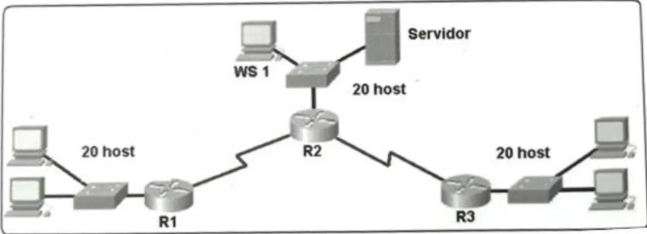
3.1. Topología de red
Los requerimientos solicitados son los siguientes:
Parte 1: Para el direccionamiento IP debe definirse una dirección de acuerdo con el número de hosts requeridos.
Parte 2: Considerar la asignación de los parámetros básicos y la detección de vecinos directamente conectados.
Parte 3: La red y subred establecidas deberán tener una interconexión total, todos los hosts deberán ser visibles y poder comunicarse entre ellos sin restricciones.
Parte 4: Implementar la seguridad en la red, se debe restringir el acceso y comunicación entre hosts de acuerdo con los requerimientos del administrador de red.
11 Ilustración 1 Tipología de red "a"
Fuente 1 Investigación del autor
Ilustración 2 Tipología de red "b"
12 Ilustración 3 Tipología de red "en tiempo real"
Fuente 3 Investigacion del Autor
3.2. Desarrollo
Como trabajo inicial se debe realizar lo siguiente.
Realizar las rutinas de diagnóstico y dejar los equipos listos para su
configuración (asignar nombres de equipos, asignar claves de seguridad, etc).
Router>en
Router#conf term
13 BOGOTA(config)#no ip domain-lookup
BOGOTA(config)#service password-encryption
BOGOTA(config)#banner motd #Cuidado Acceso Restringido# BOGOTA(config)#enable secret class123
BOGOTA(config)#line console 0
BOGOTA(config-line)#password cisco123 BOGOTA(config-line)#login
BOGOTA(config-line)#logging synchronous BOGOTA(config-line)#line vty 0 15
BOGOTA(config-line)#password cisco123 BOGOTA(config-line)#login
BOGOTA(config-line)#logging synchronous BOGOTA(config-line)#
BOGOTA(config-line)#
Router>en
Router#conf term
Enter configuration commands, one per line. End with CNTL/Z. Router(config)#hostname MEDELLIN
MEDELLIN(config)#no ip domain-lookup
MEDELLIN(config)#service password-encryption
MEDELLIN(config)#banner motd #Cuidado Acceso Restringido# MEDELLIN(config)#enable secret class123
14 MEDELLIN(config-line)#password cisco123 MEDELLIN(config-line)#login
MEDELLIN(config-line)#logging synchronous MEDELLIN(config-line)#line vty 0 15
MEDELLIN(config-line)#password cisco123 MEDELLIN(config-line)#login
MEDELLIN(config-line)#logging synchronous MEDELLIN(config-line)#
Router>en
Router#conf term
Enter configuration commands, one per line. End with CNTL/Z. Router(config)#hostname CALI
CALI(config)#no ip domain-lookup
CALI(config)#service password-encryption
CALI(config)#banner motd #Cuidado Acceso Restringido# CALI(config)#enable secret class123
CALI(config)#line console 0
CALI(config-line)#password cisco123 CALI(config-line)#login
CALI(config-line)#logging synchronous CALI(config-line)#line vty 0 15
15 CALI(config-line)#logging synchronous CALI(config-line)#
Switch>en
Switch#conf term
Enter configuration commands, one per line. End with CNTL/Z. Switch(config)#hostname BOGOTASW
BOGOTASW(config)#no ip domain-lookup
BOGOTASW(config)#service password-encryption
BOGOTASW(config)#banner motd #Cuidado Acceso Restringido# BOGOTASW(config)#enable secret class123
BOGOTASW(config)#line console 0
BOGOTASW(config-line)#password cisco123 BOGOTASW(config-line)#login
BOGOTASW(config-line)#logging synchronous BOGOTASW(config-line)#line vty 0 15
BOGOTASW(config-line)#password cisco123 BOGOTASW(config-line)#login
BOGOTASW(config-line)#logging synchronous BOGOTASW(config-line)#
BOGOTASW(config-line)#
16 Switch#conf term
Enter configuration commands, one per line. End with CNTL/Z. Switch(config)#hostname MEDELLINSW
MEDELLINSW(config)#no ip domain-lookup
MEDELLINSW(config)#service password-encryption
MEDELLINSW(config)#banner motd #Cuidado Acceso Restringido# MEDELLINSW(config)#enable secret class123
MEDELLINSW(config)#line console 0
MEDELLINSW(config-line)#password cisco123 MEDELLINSW(config-line)#login
MEDELLINSW(config-line)#logging synchronous MEDELLINSW(config-line)#line vty 0 15
MEDELLINSW(config-line)#password cisco123 MEDELLINSW(config-line)#login
MEDELLINSW(config-line)#logging synchronous MEDELLINSW(config-line)#
MEDELLINSW(config-line)#
Switch>en
Switch#conf term
Enter configuration commands, one per line. End with CNTL/Z. Switch(config)#hostname CALISW
CALISW(config)#no ip domain-lookup
17
CALISW(config)#banner motd #Cuidado Acceso Restringido# CALISW(config)#enable secret class123
CALISW(config)#line console 0
CALISW(config-line)#password cisco123 CALISW(config-line)#login
CALISW(config-line)#logging synchronous CALISW(config-line)#line vty 0 15
CALISW(config-line)#password cisco123 CALISW(config-line)#login
CALISW(config-line)#logging synchronous CALISW(config-line)#
Realizar la conexión fisica de los equipos con base en la topología
de red
Configurar la topología de red, de acuerdo con las siguientes
especificaciones.
3.2.1. Parte 1: Asignación de direcciones IP:
a. Se debe dividir (subnetear) la red creando una segmentación en ocho
partes, para permitir creciemiento futuro de la red corporativa.
b. Asignar una dirección IP a la red.
LAN Bogota 192.168.1.0/27
18 LAN Cali 192.168.1.64/27 Bogota - Medellín 192.168.1.96/27 Bogota - Cali 192.168.1.128/27 Red Futura 192.168.1.160/27 Red Futura 192.168.1.192/27 Red Futura 192.168.1.224/27
3.2.2 Parte 2: Configuración Básica.
a. Completar la siguiente tabla con la configuración básica de los routers,
teniendo en cuenta las subredes diseñadas.
Ilustración 4 Configuración de los Routers
R1 R2 R3
Nombre de Host MEDELLIN BOGOTA CALI
Dirección de Ip en interfaz Serial 0/0
192.168.1.99 192.168.1.98 192.168.1.131
Dirección de Ip en interfaz Serial 0/1
192.168.1.130
Dirección de Ip en interfaz FA 0/0
192.168.1.33 192.168.1.1 192.168.1.65
Protocolo de enrutamiento Eigrp Eigrp Eigrp
Sistema Autónomo 200 200 200
Afirmaciones de red 192.168.1.0 192.168.1.0 192.168.1.0
Fuente 4 Elaboración Propia
BOGOTA(config-line)#int s0/0/0
BOGOTA(config-if)#ip address 192.168.1.98 255.255.255.224 BOGOTA(config-if)#no shutdown
19 BOGOTA(config-if)#int s0/0/1
BOGOTA(config-if)#ip address 192.168.1.130 255.255.255.224 BOGOTA(config-if)#no shutdown
%LINK-5-CHANGED: Interface Serial0/0/1, changed state to down BOGOTA(config-if)#
BOGOTA(config-if)#int f0/0
BOGOTA(config-if)#ip address 192.168.1.1 255.255.255.224 BOGOTA(config-if)#no shutdown
BOGOTA(config-if)#
BOGOTA(config-if)#router eigrp 200
BOGOTA(config-router)#no auto-summary
BOGOTA(config-router)#network 192.168.1.0 0.0.0.31 BOGOTA(config-router)#network 192.168.1.96 0.0.0.31 BOGOTA(config-router)#network 192.168.1.128 0.0.0.31 BOGOTA(config-router)#
BOGOTA(config-router)#end BOGOTA#
%LINK-5-CHANGED: Interface FastEthernet0/0, changed state to up
20
%SYS-5-CONFIG_I: Configured from console by console
BOGOTA#
MEDELLIN(config-line)#int s0/0/0
MEDELLIN(config-if)#ip address 192.168.1.99 255.255.255.224 MEDELLIN(config-if)#no shutdown
MEDELLIN(config-if)#
MEDELLIN(config-if)#int f0/0
MEDELLIN(config-if)#ip address 192.168.1.33 255.255.255.224 MEDELLIN(config-if)#no shutdown
MEDELLIN(config-if)#
MEDELLIN(config-if)#router eigrp 200
MEDELLIN(config-router)#no auto-summary
MEDELLIN(config-router)#network 192.168.1.32 0.0.0.31 MEDELLIN(config-router)#network 192.168.1.96 0.0.0.31 MEDELLIN(config-router)#end
MEDELLIN# MEDELLIN#
%LINK-5-CHANGED: Interface Serial0/0/0, changed state to up
21
%LINEPROTO-5-UPDOWN: Line protocol on Interface FastEthernet0/0, changed state to up
%SYS-5-CONFIG_I: Configured from console by console
MEDELLIN#
%LINEPROTO-5-UPDOWN: Line protocol on Interface Serial0/0/0, changed state to up
%DUAL-5-NBRCHANGE: IP-EIGRP 200: Neighbor 192.168.1.98 (Serial0/0/0) is up: new adjacency
MEDELLIN#
CALI(config-line)#int s0/0/0
CALI(config-if)#ip address 192.168.1.131 255.255.255.224 CALI(config-if)#no shutdown
CALI(config-if)#int f0/0
CALI(config-if)#ip address 192.168.1.65 255.255.255.224 CALI(config-if)#no shutdown
22 CALI(config-if)#router eigrp 200
CALI(config-router)#no auto-summary
CALI(config-router)#network 192.168.1.64 0.0.0.31 CALI(config-router)#network 192.168.1.128 0.0.0.31 CALI(config-router)#end
CALI# CALI#
%LINK-5-CHANGED: Interface Serial0/0/0, changed state to up
%LINK-5-CHANGED: Interface FastEthernet0/0, changed state to up
%LINEPROTO-5-UPDOWN: Line protocol on Interface FastEthernet0/0, changed state to up
%SYS-5-CONFIG_I: Configured from console by console
CALI#
%LINEPROTO-5-UPDOWN: Line protocol on Interface Serial0/0/0, changed state to up
%DUAL-5-NBRCHANGE: IP-EIGRP 200: Neighbor 192.168.1.130 (Serial0/0/0) is up: new adjacency
23
b. Después de cargada la configuración en los dispositivos, verificar la
tabla de enrutamiento en cada uno de los routers para comprobar las redes
y sus rutas.
BOGOTA#show ip route
Codes: C - connected, S - static, I - IGRP, R - RIP, M - mobile, B - BGP D - EIGRP, EX - EIGRP external, O - OSPF, IA - OSPF inter area N1 - OSPF NSSA external type 1, N2 - OSPF NSSA external type 2 E1 - OSPF external type 1, E2 - OSPF external type 2, E - EGP i - IS-IS, L1 - IS-IS level-1, L2 - IS-IS level-2, ia - IS-IS inter area * - candidate default, U - per-user static route, o - ODR
P - periodic downloaded static route
Gateway of last resort is not set
192.168.1.0/27 is subnetted, 5 subnets
C 192.168.1.0 is directly connected, FastEthernet0/0
D 192.168.1.32 [90/2172416] via 192.168.1.99, 00:02:57, Serial0/0/0 D 192.168.1.64 [90/2172416] via 192.168.1.131, 00:02:10, Serial0/0/1 C 192.168.1.96 is directly connected, Serial0/0/0
C 192.168.1.128 is directly connected, Serial0/0/1
24 MEDELLIN#show ip route
Codes: C - connected, S - static, I - IGRP, R - RIP, M - mobile, B - BGP D - EIGRP, EX - EIGRP external, O - OSPF, IA - OSPF inter area N1 - OSPF NSSA external type 1, N2 - OSPF NSSA external type 2 E1 - OSPF external type 1, E2 - OSPF external type 2, E - EGP i - IS-IS, L1 - IS-IS level-1, L2 - IS-IS level-2, ia - IS-IS inter area * - candidate default, U - per-user static route, o - ODR
P - periodic downloaded static route
Gateway of last resort is not set
192.168.1.0/27 is subnetted, 5 subnets
D 192.168.1.0 [90/2172416] via 192.168.1.98, 00:04:09, Serial0/0/0 C 192.168.1.32 is directly connected, FastEthernet0/0
D 192.168.1.64 [90/2684416] via 192.168.1.98, 00:03:22, Serial0/0/0 C 192.168.1.96 is directly connected, Serial0/0/0
D 192.168.1.128 [90/2681856] via 192.168.1.98, 00:03:29, Serial0/0/0
CALI#show ip route
25
* - candidate default, U - per-user static route, o - ODR P - periodic downloaded static route
Gateway of last resort is not set
192.168.1.0/27 is subnetted, 5 subnets
D 192.168.1.0 [90/2172416] via 192.168.1.130, 00:04:10, Serial0/0/0 D 192.168.1.32 [90/2684416] via 192.168.1.130, 00:04:10, Serial0/0/0 C 192.168.1.64 is directly connected, FastEthernet0/0
D 192.168.1.96 [90/2681856] via 192.168.1.130, 00:04:10, Serial0/0/0 C 192.168.1.128 is directly connected, Serial0/0/0
c. Verificar el balanceo de carga que presentan los routers.
BOGOTA#show ip eigrp topology
IP-EIGRP Topology Table for AS 200/ID(192.168.1.130)
Codes: P - Passive, A - Active, U - Update, Q - Query, R - Reply, r - Reply status
P 192.168.1.0/27, 1 successors, FD is 28160 via Connected, FastEthernet0/0
26
via 192.168.1.131 (2172416/28160), Serial0/0/1 P 192.168.1.96/27, 1 successors, FD is 2169856 via Connected, Serial0/0/0
P 192.168.1.128/27, 1 successors, FD is 2169856 via Connected, Serial0/0/1
MEDELLIN#show ip eigrp topology
IP-EIGRP Topology Table for AS 200/ID(192.168.1.99)
Codes: P - Passive, A - Active, U - Update, Q - Query, R - Reply, r - Reply status
P 192.168.1.0/27, 1 successors, FD is 2172416 via 192.168.1.98 (2172416/28160), Serial0/0/0 P 192.168.1.32/27, 1 successors, FD is 28160 via Connected, FastEthernet0/0
P 192.168.1.64/27, 1 successors, FD is 2684416 via 192.168.1.98 (2684416/2172416), Serial0/0/0 P 192.168.1.96/27, 1 successors, FD is 2169856 via Connected, Serial0/0/0
27 CALI#show ip eigrp topology
IP-EIGRP Topology Table for AS 200/ID(192.168.1.131)
Codes: P - Passive, A - Active, U - Update, Q - Query, R - Reply, r - Reply status
P 192.168.1.0/27, 1 successors, FD is 2172416 via 192.168.1.130 (2172416/28160), Serial0/0/0 P 192.168.1.32/27, 1 successors, FD is 2684416 via 192.168.1.130 (2684416/2172416), Serial0/0/0 P 192.168.1.64/27, 1 successors, FD is 28160 via Connected, FastEthernet0/0
P 192.168.1.96/27, 1 successors, FD is 2681856 via 192.168.1.130 (2681856/2169856), Serial0/0/0 P 192.168.1.128/27, 1 successors, FD is 2169856 via Connected, Serial0/0/0
d. Realizar un diagnóstico de vecinos uando el comando cdp.
BOGOTA#show cdp neighbor
Capability Codes: R - Router, T - Trans Bridge, B - Source Route Bridge S - Switch, H - Host, I - IGMP, r - Repeater, P - Phone
Device ID Local Intrfce Holdtme Capability Platform Port ID BOGOTASW Fas 0/0 124 S 2960 Fas 0/1
28 CALI Ser 0/0/1 170 R C1841 Ser 0/0/0 BOGOTA#
MEDELLIN#show cdp neighbor
Capability Codes: R - Router, T - Trans Bridge, B - Source Route Bridge S - Switch, H - Host, I - IGMP, r - Repeater, P - Phone
Device ID Local Intrfce Holdtme Capability Platform Port ID MEDELLINSW Fas 0/0 166 S 2960 Fas 0/1
BOGOTA Ser 0/0/0 151 R C1841 Ser 0/0/0 MEDELLIN#
CALI#show cdp neighbor
Capability Codes: R - Router, T - Trans Bridge, B - Source Route Bridge S - Switch, H - Host, I - IGMP, r - Repeater, P - Phone
Device ID Local Intrfce Holdtme Capability Platform Port ID CALISW Fas 0/0 162 S 2960 Fas 0/1
BOGOTA Ser 0/0/0 163 R C1841 Ser 0/0/1 CALI#show ip eigrp neighbor
IP-EIGRP neighbors for process 200
H Address Interface Hold Uptime SRTT RTO Q Seq (sec) (ms) Cnt Num
0 192.168.1.130 Se0/0/0 12 00:04:10 40 1000 0 8
29
e. Realizar una prueba de conectividad en cada tramo de la ruta usando
Ping.
CALI#ping 192.168.1.130
Type escape sequence to abort.
Sending 5, 100-byte ICMP Echos to 192.168.1.130, timeout is 2 seconds: !!!!!
Success rate is 100 percent (5/5), round-trip min/avg/max = 2/4/9 ms
CALI#ping 192.168.1.99
Type escape sequence to abort.
Sending 5, 100-byte ICMP Echos to 192.168.1.99, timeout is 2 seconds: !!!!!
Success rate is 100 percent (5/5), round-trip min/avg/max = 3/4/6 ms
CALI#
BOGOTA#ping 192.168.1.99
Type escape sequence to abort.
30
Success rate is 100 percent (5/5), round-trip min/avg/max = 1/3/6 ms
BOGOTA#ping 192.168.1.131
Type escape sequence to abort.
Sending 5, 100-byte ICMP Echos to 192.168.1.131, timeout is 2 seconds: !!!!!
Success rate is 100 percent (5/5), round-trip min/avg/max = 2/3/7 ms
BOGOTA#
3.2.3 Parte 3: Configuración de Enrutamiento.
a. Asignar el protocolo de enrutamiento EIGRP a los routers considerando
el direccionamiento diseñado.
b. Verificar si existe vecindad con los routers configurados con EIGRP.
SHOW IP EIGRP NEIGHBORS
BOGOTA#show ip eigrp neighbor IP-EIGRP neighbors for process 200
H Address Interface Hold Uptime SRTT RTO Q Seq (sec) (ms) Cnt Num
31 BOGOTA#
MEDELLIN#show ip eigrp neighbor IP-EIGRP neighbors for process 200
H Address Interface Hold Uptime SRTT RTO Q Seq (sec) (ms) Cnt Num
0 192.168.1.98 Se0/0/0 12 00:10:34 40 1000 0 7
MEDELLIN#
CALI#show ip eigrp neighbor
IP-EIGRP neighbors for process 200
H Address Interface Hold Uptime SRTT RTO Q Seq (sec) (ms) Cnt Num
0 192.168.1.130 Se0/0/0 10 00:10:07 40 1000 0 8
CALI#
SHOW IP EIGRP TOPOLOGY
BOGOTA#show ip eigrp topology
32
Codes: P - Passive, A - Active, U - Update, Q - Query, R - Reply, r - Reply status
P 192.168.1.0/27, 1 successors, FD is 28160 via Connected, FastEthernet0/0
P 192.168.1.32/27, 1 successors, FD is 2172416 via 192.168.1.99 (2172416/28160), Serial0/0/0 P 192.168.1.64/27, 1 successors, FD is 2172416 via 192.168.1.131 (2172416/28160), Serial0/0/1 P 192.168.1.96/27, 1 successors, FD is 2169856 via Connected, Serial0/0/0
P 192.168.1.128/27, 1 successors, FD is 2169856 via Connected, Serial0/0/1
MEDELLIN#show ip eigrp topology
IP-EIGRP Topology Table for AS 200/ID(192.168.1.99)
Codes: P - Passive, A - Active, U - Update, Q - Query, R - Reply, r - Reply status
33
P 192.168.1.64/27, 1 successors, FD is 2684416 via 192.168.1.98 (2684416/2172416), Serial0/0/0 P 192.168.1.96/27, 1 successors, FD is 2169856 via Connected, Serial0/0/0
P 192.168.1.128/27, 1 successors, FD is 2681856 via 192.168.1.98 (2681856/2169856), Serial0/0/0
CALI#show ip eigrp topology
IP-EIGRP Topology Table for AS 200/ID(192.168.1.131)
Codes: P - Passive, A - Active, U - Update, Q - Query, R - Reply, r - Reply status
P 192.168.1.0/27, 1 successors, FD is 2172416 via 192.168.1.130 (2172416/28160), Serial0/0/0 P 192.168.1.32/27, 1 successors, FD is 2684416 via 192.168.1.130 (2684416/2172416), Serial0/0/0 P 192.168.1.64/27, 1 successors, FD is 28160 via Connected, FastEthernet0/0
34
c. Realizar la comprobación de las tablas de enrutamiento en cada uno de
los routers para verificar cada una de las rutas establecidas.
SHOW IP ROUTE
BOGOTA#show ip route
Codes: C - connected, S - static, I - IGRP, R - RIP, M - mobile, B - BGP D - EIGRP, EX - EIGRP external, O - OSPF, IA - OSPF inter area N1 - OSPF NSSA external type 1, N2 - OSPF NSSA external type 2 E1 - OSPF external type 1, E2 - OSPF external type 2, E - EGP i - IS-IS, L1 - IS-IS level-1, L2 - IS-IS level-2, ia - IS-IS inter area * - candidate default, U - per-user static route, o - ODR
P - periodic downloaded static route
Gateway of last resort is not set
192.168.1.0/27 is subnetted, 5 subnets
C 192.168.1.0 is directly connected, FastEthernet0/0
D 192.168.1.32 [90/2172416] via 192.168.1.99, 00:02:57, Serial0/0/0 D 192.168.1.64 [90/2172416] via 192.168.1.131, 00:02:10, Serial0/0/1 C 192.168.1.96 is directly connected, Serial0/0/0
C 192.168.1.128 is directly connected, Serial0/0/1
35 MEDELLIN#show ip route
Codes: C - connected, S - static, I - IGRP, R - RIP, M - mobile, B - BGP D - EIGRP, EX - EIGRP external, O - OSPF, IA - OSPF inter area N1 - OSPF NSSA external type 1, N2 - OSPF NSSA external type 2 E1 - OSPF external type 1, E2 - OSPF external type 2, E - EGP i - IS-IS, L1 - IS-IS level-1, L2 - IS-IS level-2, ia - IS-IS inter area * - candidate default, U - per-user static route, o - ODR
P - periodic downloaded static route
Gateway of last resort is not set
192.168.1.0/27 is subnetted, 5 subnets
D 192.168.1.0 [90/2172416] via 192.168.1.98, 00:04:09, Serial0/0/0 C 192.168.1.32 is directly connected, FastEthernet0/0
D 192.168.1.64 [90/2684416] via 192.168.1.98, 00:03:22, Serial0/0/0 C 192.168.1.96 is directly connected, Serial0/0/0
D 192.168.1.128 [90/2681856] via 192.168.1.98, 00:03:29, Serial0/0/0
CALI#show ip route
36
i - IS-IS, L1 - IS-IS level-1, L2 - IS-IS level-2, ia - IS-IS inter area * - candidate default, U - per-user static route, o - ODR
P - periodic downloaded static route
Gateway of last resort is not set
192.168.1.0/27 is subnetted, 5 subnets
D 192.168.1.0 [90/2172416] via 192.168.1.130, 00:04:10, Serial0/0/0 D 192.168.1.32 [90/2684416] via 192.168.1.130, 00:04:10, Serial0/0/0 C 192.168.1.64 is directly connected, FastEthernet0/0
D 192.168.1.96 [90/2681856] via 192.168.1.130, 00:04:10, Serial0/0/0 C 192.168.1.128 is directly connected, Serial0/0/0
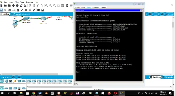
d. Realizar un diagnóstico para comprobar que cada uno de los puntos de
la red se puedan ver y tengan conectividad entre sí. Realizar esta prueba
desde un host de la red LAN del router CALI, primero a la red de MEDELLIN
37 Ilustración 6 Prueba B desde un Host (Pantalla 2)
Fuente 6 Elaboración Propia
Ilustración 5 Prueba desde un Host (Pantalla 1)
38
3.2.4 Parte 4: Configuración de las listas de Control de Acceso.
En este momento cualquier usuario de la red tiene acceso a todos sus dispositivos y estaciones de trabajo. El jefe de redes le solicita implementar seguridad en la red. Para esta labor se decide configurar listas de control de acceso (ACL) a los routers.
Las condiciones para crear las ACL son las siguientes:
a. Cada router debe estar habilitado para establecer conexiones
Telnet con los demás routers y tener acceso a cualquier dispositivo en la
red.
b. El equipo WS1 y el servidor se encuentran en la subred de
administración. Solo el servidor de la subred de administración debe tener
acceso a cualquier otro dispositivo en cualquier parte de la red.
BOGOTA#conf term
Enter configuration commands, one per line. End with CNTL/Z. BOGOTA(config)#access-list 111 permit ip host 192.168.1.30 any BOGOTA(config)#int f0/0
39
c. Las estaciones de trabajo en las LAN de MEDELLIN y CALI no deben
tener acceso a ningún dispositivo fuera de su subred, excepto para
interconectar con el servidor.
MEDELLIN#conf t
Enter configuration commands, one per line. End with CNTL/Z.
MEDELLIN(config)#access-list 111 permit ip 192.168.1.32 0.0.0.31 host 192.168.1.30
MEDELLIN(config)#int f0/0
MEDELLIN(config-if)#ip access-group 111 in MEDELLIN(config-if)#
CALI#conf t
Enter configuration commands, one per line. End with CNTL/Z.
CALI(config)#access-list 111 permit ip 192.168.1.64 0.0.0.31 host 192.168.1.30 CALI(config)#int f0/0
40
3.2.5 Parte 5: Comprobación de la red instalada.
a. Se debe probar que la configuración de las listas de acceso fue exitosa.
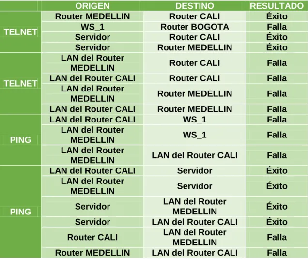
b. Comprobar y Completar la siguiente tabla de condiciones de prueba para
confirmar el óptimo funcionamiento de la red e.
Ilustración 7 Condiciones de Prueba
ORIGEN DESTINO RESULTADO
TELNET
Router MEDELLIN Router CALI Éxito
WS_1 Router BOGOTA Falla
Servidor Router CALI Éxito
Servidor Router MEDELLIN Éxito
TELNET
LAN del Router
MEDELLIN Router CALI Falla
LAN del Router CALI Router CALI Falla
LAN del Router
MEDELLIN Router MEDELLIN Falla
LAN del Router CALI Router MEDELLIN Falla
PING
LAN del Router CALI WS_1 Falla
LAN del Router
MEDELLIN WS_1 Falla
LAN del Router
MEDELLIN LAN del Router CALI Falla
PING
LAN del Router CALI Servidor Éxito
LAN del Router
MEDELLIN Servidor Éxito
Servidor LAN del Router
MEDELLIN Éxito
Servidor LAN del Router CALI Éxito
Router CALI LAN del Router
MEDELLIN Falla
Router MEDELLIN LAN del Router CALI Falla
41 Ilustración 8 Prueba de Red Instalada 1
Fuente 8 Elaboracion Propia
Ilustración 9 Prueba de Red Instalada 2
42 Ilustración 10 Prueba de Red Instalada 3
Fuente 10 Elaboración Propia
Ilustración 11 Prueba de Red Instalada 4
43 Ilustración 12 Prueba de Red Instalada 5
Fuente 12 Elaboracion Propia
Ilustración 13 Prueba de Red Instalada 6
44 Ilustración 14 Prueba de Red Instalada 7
Fuente 14 Elaboración Propia
Ilustración 15 Prueba de Red Instalada 8
45 Ilustración 16 Prueba de Red Instalada 9
Fuente 16 Elaboración Propia
Ilustración 17 Prueba de Red Instalada 10
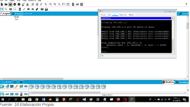
46 Ilustración 18 Prueba de Red Instalada 11
Fuente 18 Elaboración Propia
Ilustración 19 Prueba de Red Instalada 12
47 Ilustración 20 Prueba de Red Instalada 13
Fuente 20 Elaboración Propia
Ilustración 21 Prueba de Red Instalada 14
48 Ilustración 22 Prueba de Red Instalada 15
49 Ilustración 23 Diagrama de Red de Empresa
Fuente 23 Elaboración Propia
4. Escenario 2
Una empresa tiene la conexión a internet en una red Ethernet, lo cual
deben adaptarlo para facilitar que sus routers y las redes que incluyen
puedan, por esa vía, conectarse a internet, pero empleando las
50 Fuente 24 Elaboración Propia
Ilustración 24 Diagrama de Empresa en el Programa
4.1 Desarrollo
Los siguientes son los requerimientos necesarios:
4.1.1 Todos los routers deberán tener los siguiente:
Configuración básica.
Router>en
Router#conf term
Enter configuration commands, one per line. End with CNTL/Z. Router(config)#hostname BUCARAMANGA
51
BUCARAMANGA(config)#banner motd #Cuidado Acceso Restringido# BUCARAMANGA(config)#enable secret class123
BUCARAMANGA(config)#line console 0
BUCARAMANGA(config-line)#password cisco123 BUCARAMANGA(config-line)#login
BUCARAMANGA(config-line)#logging synchronous BUCARAMANGA(config-line)#line vty 0 15
BUCARAMANGA(config-line)#password cisco123 BUCARAMANGA(config-line)#login
BUCARAMANGA(config-line)#logging synchronous BUCARAMANGA(config)#int f0/0.1
BUCARAMANGA(config-subif)#encapsulation dot1q 1
BUCARAMANGA(config-subif)#ip address 172.31.2.1 255.255.255.248 BUCARAMANGA(config-subif)#int f0/0.10
BUCARAMANGA(config-subif)#encapsulation dot1q 10
BUCARAMANGA(config-subif)#ip address 172.31.0.1 255.255.255.192 BUCARAMANGA(config-subif)#int f0/0.30
BUCARAMANGA(config-subif)#encapsulation dot1q 30
BUCARAMANGA(config-subif)#ip address 172.31.0.65 255.255.255.192 BUCARAMANGA(config-subif)#int f0/0
BUCARAMANGA(config-if)#no shutdown
52 BUCARAMANGA(config-if)#int s0/0/0
BUCARAMANGA(config-if)#ip address 172.31.2.34 255.255.255.252 BUCARAMANGA(config-if)#no shutdown
%LINK-5-CHANGED: Interface Serial0/0/0, changed state to down BUCARAMANGA(config-if)#
BUCARAMANGA(config-if)#router ospf 1
BUCARAMANGA(config-router)#network 172.31.0.0 0.0.0.63 area 0 BUCARAMANGA(config-router)#network 172.31.0.64 0.0.0.63 area 0 BUCARAMANGA(config-router)#network 172.31.2.0 0.0.0.7 area 0 BUCARAMANGA(config-router)#network 172.31.2.32 0.0.0.3 area 0 BUCARAMANGA(config-router)#end
BUCARAMANGA#
%LINK-5-CHANGED: Interface FastEthernet0/0, changed state to up
%LINEPROTO-5-UPDOWN: Line protocol on Interface FastEthernet0/0, changed state to up
%LINK-5-CHANGED: Interface FastEthernet0/0.1, changed state to up
%LINEPROTO-5-UPDOWN: Line protocol on Interface FastEthernet0/0.1, changed state to up
53
%LINEPROTO-5-UPDOWN: Line protocol on Interface FastEthernet0/0.10, changed state to up
%LINK-5-CHANGED: Interface FastEthernet0/0.30, changed state to up
%LINEPROTO-5-UPDOWN: Line protocol on Interface FastEthernet0/0.30, changed state to up
%SYS-5-CONFIG_I: Configured from console by console
BUCARAMANGA#
Router>en
Router#conf term
Enter configuration commands, one per line. End with CNTL/Z. Router(config)#hostname TUNJA
TUNJA(config)#no ip domain-lookup
TUNJA(config)#banner motd #Cuidado Acceso Restringido# TUNJA(config)#enable secret class123
TUNJA(config)#line console 0
TUNJA(config-line)#password cisco123 TUNJA(config-line)#login
54 TUNJA(config-line)#line vty 0 15
TUNJA(config-line)#password cisco123 TUNJA(config-line)#login
TUNJA(config-line)#logging synchronous TUNJA(config)#int f0/0.1
TUNJA(config-subif)#encapsulation dot1q 1
TUNJA(config-subif)#ip address 172.3.2.9 255.255.255.248 TUNJA(config-subif)#int f0/0.20
TUNJA(config-subif)#encapsulation dot1q 20
TUNJA(config-subif)#ip address 172.31.0.129 255.255.255.192 TUNJA(config-subif)#int f0/0.30
TUNJA(config-subif)#encapsulation dot1q 30
TUNJA(config-subif)#ip address 172.31.0.193 255.255.255.192 TUNJA(config-subif)#int f0/0
TUNJA(config-if)#no shutdown
TUNJA(config-if)#
TUNJA(config-if)#int s0/0/0
TUNJA(config-if)#ip address 172.31.2.33 255.255.255.252 TUNJA(config-if)#no shutdown
TUNJA(config-if)#
TUNJA(config-if)#int s0/0/1
55 TUNJA(config-if)#no shutdown
%LINK-5-CHANGED: Interface Serial0/0/1, changed state to down TUNJA(config-if)#int f0/1
TUNJA(config-if)#ip address 209.165.220.1 255.255.255.0 TUNJA(config-if)#no shutdown
TUNJA(config-if)#
TUNJA(config-if)#router ospf 1
TUNJA(config-router)#network 172.3.2.8 0.0.0.7 area 0 TUNJA(config-router)#network 172.31.0.128 0.0.0.63 area 0 TUNJA(config-router)#network 172.31.0.192 0.0.0.63 area 0 TUNJA(config-router)#network 172.31.2.32 0.0.0.3 area 0 TUNJA(config-router)#network 172.31.2.36 0.0.0.3 area 0 TUNJA(config-router)#end
TUNJA# TUNJA#
%LINK-5-CHANGED: Interface FastEthernet0/0, changed state to up
%LINEPROTO-5-UPDOWN: Line protocol on Interface FastEthernet0/0, changed state to up
56
%LINEPROTO-5-UPDOWN: Line protocol on Interface FastEthernet0/0.1, changed state to up
%LINK-5-CHANGED: Interface FastEthernet0/0.20, changed state to up
%LINEPROTO-5-UPDOWN: Line protocol on Interface FastEthernet0/0.20, changed state to up
%LINK-5-CHANGED: Interface FastEthernet0/0.30, changed state to up
%LINEPROTO-5-UPDOWN: Line protocol on Interface FastEthernet0/0.30, changed state to up
%LINK-5-CHANGED: Interface Serial0/0/0, changed state to up
%LINK-5-CHANGED: Interface FastEthernet0/1, changed state to up
%LINEPROTO-5-UPDOWN: Line protocol on Interface FastEthernet0/1, changed state to up
%SYS-5-CONFIG_I: Configured from console by console
57 Router>en
Router#conf term
Enter configuration commands, one per line. End with CNTL/Z. Router(config)#hostname CUNDINAMARCA
CUNDINAMARCA(config)#no ip domain-lookup
CUNDINAMARCA(config)#banner motd #Cuidado Acceso Restringido# CUNDINAMARCA(config)#enable secret class123
CUNDINAMARCA(config)#line console 0
CUNDINAMARCA(config-line)#password cisco123 CUNDINAMARCA(config-line)#login
CUNDINAMARCA(config-line)#logging synchronous CUNDINAMARCA(config-line)#line vty 0 15
CUNDINAMARCA(config-line)#password cisco123 CUNDINAMARCA(config-line)#login
CUNDINAMARCA(config-line)#logging synchronous CUNDINAMARCA(config)#int f0/0.1
CUNDINAMARCA(config-subif)#encapsulation dot1q 1
CUNDINAMARCA(config-subif)#ip address 172.31.2.9 255.255.255.248 CUNDINAMARCA(config-subif)#int f0/0.20
CUNDINAMARCA(config-subif)#encapsulation dot1q 20
CUNDINAMARCA(config-subif)#ip address 172.31.1.65 255.255.255.192 CUNDINAMARCA(config-subif)#int f0/0.30
CUNDINAMARCA(config-subif)#encapsulation dot1q 30
58 CUNDINAMARCA(config-subif)#int f0/0.88
CUNDINAMARCA(config-subif)#encapsulation dot1q 88
CUNDINAMARCA(config-subif)#ip address 172.31.2.25 255.255.255.248 CUNDINAMARCA(config-subif)#int f0/0
CUNDINAMARCA(config-if)#no shutdown
CUNDINAMARCA(config-if)#
CUNDINAMARCA(config-if)#int s0/0/0
CUNDINAMARCA(config-if)#ip address 172.31.2.38 255.255.255.252 CUNDINAMARCA(config-if)#no shutdown
CUNDINAMARCA(config-if)#router ospf 1
CUNDINAMARCA(config-router)#network 172.31.1.0 0.0.0.63 area 0 CUNDINAMARCA(config-router)#network 172.31.1.64 0.0.0.63 area 0 CUNDINAMARCA(config-router)#network 172.31.2.8 0.0.0.7 area 0 CUNDINAMARCA(config-router)#network 172.31.2.24 0.0.0.7 area 0 CUNDINAMARCA(config-router)#network 172.31.2.36 0.0.0.3 area 0 CUNDINAMARCA(config-router)#end
CUNDINAMARCA#
%LINK-5-CHANGED: Interface FastEthernet0/0, changed state to up
59
%LINK-5-CHANGED: Interface FastEthernet0/0.1, changed state to up
%LINEPROTO-5-UPDOWN: Line protocol on Interface FastEthernet0/0.1, changed state to up
%LINK-5-CHANGED: Interface FastEthernet0/0.20, changed state to up
%LINEPROTO-5-UPDOWN: Line protocol on Interface FastEthernet0/0.20, changed state to up
%LINK-5-CHANGED: Interface FastEthernet0/0.30, changed state to up
%LINEPROTO-5-UPDOWN: Line protocol on Interface FastEthernet0/0.30, changed state to up
%LINK-5-CHANGED: Interface FastEthernet0/0.88, changed state to up
%LINEPROTO-5-UPDOWN: Line protocol on Interface FastEthernet0/0.88, changed state to up
%LINK-5-CHANGED: Interface Serial0/0/0, changed state to up
60 CUNDINAMARCA#
%LINEPROTO-5-UPDOWN: Line protocol on Interface Serial0/0/0, changed state to up
CUNDINAMARCA#
00:14:55: %OSPF-5-ADJCHG: Process 1, Nbr 209.165.220.1 on Serial0/0/0 from LOADING to FULL, Loading Done
CUNDINAMARCA# Switch>en
Switch#conf term
Enter configuration commands, one per line. End with CNTL/Z. Switch(config)#hostname BUCARAMANGASW
BUCARAMANGASW(config)#vlan 1 BUCARAMANGASW(config-vlan)#vlan 10 BUCARAMANGASW(config-vlan)#vlan 30 BUCARAMANGASW(config-vlan)#int f0/20
BUCARAMANGASW(config-if)#switchport mode access BUCARAMANGASW(config-if)#switchport access vlan 10 BUCARAMANGASW(config-if)#int f0/24
BUCARAMANGASW(config-if)#switchport mode access BUCARAMANGASW(config-if)#switchport access vlan 30 BUCARAMANGASW(config-if)#int f0/1
61 BUCARAMANGASW(config-if)#int vlan 1
BUCARAMANGASW(config-if)#ip address 172.31.2.3 255.255.255.248 BUCARAMANGASW(config-if)#no shutdown
BUCARAMANGASW(config-if)#ip default-gateway 172.31.2.1 BUCARAMANGASW(config)#
BUCARAMANGASW(config)#
%LINEPROTO-5-UPDOWN: Line protocol on Interface FastEthernet0/1, changed state to down
%LINEPROTO-5-UPDOWN: Line protocol on Interface FastEthernet0/1, changed state to up
%LINK-5-CHANGED: Interface Vlan1, changed state to up
62 Switch>en
Switch#conf term
Enter configuration commands, one per line. End with CNTL/Z. Switch(config)#hostname TUNJASW
TUNJASW(config)#vlan 1 TUNJASW(config-vlan)#vlan 20 TUNJASW(config-vlan)#vlan 30 TUNJASW(config-vlan)#int f0/20
TUNJASW(config-if)#switchport mode access TUNJASW(config-if)#switchport access vlan 20 TUNJASW(config-if)#int f0/24
TUNJASW(config-if)#switchport mode access TUNJASW(config-if)#switchport access vlan 30 TUNJASW(config-if)#int f0/1
TUNJASW(config-if)#switchport mode trunk
TUNJASW(config-if)#
TUNJASW(config-if)#int vlan 1
TUNJASW(config-if)#ip address 172.3.2.11 255.255.255.248 TUNJASW(config-if)#no shutdown
TUNJASW(config-if)#
63 TUNJASW(config)#
TUNJASW(config)#
%LINEPROTO-5-UPDOWN: Line protocol on Interface FastEthernet0/1, changed state to down
%LINEPROTO-5-UPDOWN: Line protocol on Interface FastEthernet0/1, changed state to up
%LINK-5-CHANGED: Interface Vlan1, changed state to up
%LINEPROTO-5-UPDOWN: Line protocol on Interface Vlan1, changed state to up
TUNJASW(config)#
Switch>en
Switch#conf term
Enter configuration commands, one per line. End with CNTL/Z. Switch(config)#hostname CUNDINAMARCASW
64 CUNDINAMARCASW(config)#int f0/20
CUNDINAMARCASW(config-if)#switchport mode access CUNDINAMARCASW(config-if)#switchport access vlan 20 CUNDINAMARCASW(config-if)#int f0/24
CUNDINAMARCASW(config-if)#switchport mode access CUNDINAMARCASW(config-if)#switchport access vlan 30 CUNDINAMARCASW(config-if)#int f0/10
CUNDINAMARCASW(config-if)#switchport mode access CUNDINAMARCASW(config-if)#switchport access vlan 88 CUNDINAMARCASW(config-if)#int f0/1
CUNDINAMARCASW(config-if)#switchport mode trunk
CUNDINAMARCASW(config-if)#
CUNDINAMARCASW(config-if)#int vlan 1
CUNDINAMARCASW(config-if)#ip address 172.31.2.11 255.255.255.248 CUNDINAMARCASW(config-if)#no shutdown
CUNDINAMARCASW(config-if)#
CUNDINAMARCASW(config-if)#ip default-gateway 172.31.2.9 CUNDINAMARCASW(config)#
CUNDINAMARCASW(config)#
65
%LINEPROTO-5-UPDOWN: Line protocol on Interface FastEthernet0/1, changed state to up
%LINK-5-CHANGED: Interface Vlan1, changed state to up
%LINEPROTO-5-UPDOWN: Line protocol on Interface Vlan1, changed state to up
66
Autenticación local con AAA.
BUCARAMANGA(config-line)#username administrador secret cisco12345 BUCARAMANGA(config)#aaa new-model
BUCARAMANGA(config)#aaa authentication login AUTH local BUCARAMANGA(config)#line console 0
BUCARAMANGA(config-line)#login authentication AUTH BUCARAMANGA(config-line)#line vty 0 15
BUCARAMANGA(config-line)#login authentication AUTH
TUNJA(config-line)#username administrador secret cisco12345 TUNJA(config)#aaa new-model
TUNJA(config)#aaa authentication login AUTH local TUNJA(config)#line console 0
TUNJA(config-line)#login authentication AUTH TUNJA(config-line)#line vty 0 15
TUNJA(config-line)#login authentication AUTH
CUNDINAMARCA(config-line)#username administrador secret cisco12345 CUNDINAMARCA(config)#aaa new-model
CUNDINAMARCA(config)#aaa authentication login AUTH local CUNDINAMARCA(config)#line console 0
67
CUNDINAMARCA(config-line)#login authentication AUTH
Cifrado de contraseñas.
BUCARAMANGA(config)#service password-encryption
TUNJA(config)#service password-encryption
CUNDINAMARCA(config)#service password-encryption
Un máximo de internos para acceder al router.
BUCARAMANGA(config-line)#login block-for 5 attempts 4 within 60
TUNJA(config-line)#login block-for 5 attempts 4 within 60
CUNDINAMARCA(config-line)#login block-for 5 attempts 4 within 60
Máximo tiempo de acceso al detectar ataques.
68
TUNJA(config-line)#login block-for 5 attempts 4 within 60
CUNDINAMARCA(config-line)#login block-for 5 attempts 4 within 60
Establezca un servidor TFTP y almacene todos los archivos
necesarios de los routers
Ilustración 25 Creacion de Servidor y Almacenamiento de Archivos 1
69
Ilustración 26 Creacion de Servidor y Almacenamiento de Archivos 2
Fuente 26 Elaboración Propia
El DHCP deberá proporcionar solo direcciones a los hosts de
Bucaramanga y Cundinamarca
TUNJA(config)#ip dhcp excluded-address 172.31.0.1 TUNJA(config)#ip dhcp excluded-address 172.31.0.65 TUNJA(config)#ip dhcp excluded-address 172.31.1.65 TUNJA(config)#ip dhcp excluded-address 172.31.1.1 TUNJA(config)#ip dhcp pool V10B
TUNJA(dhcp-config)#network 172.31.0.0 255.255.255.192 TUNJA(dhcp-config)#default-router 172.31.0.1
70
TUNJA(dhcp-config)#network 172.31.0.64 255.255.255.192 TUNJA(dhcp-config)#default-router 172.31.0.65
TUNJA(dhcp-config)#dns-server 172.31.2.28 TUNJA(dhcp-config)#ip dhcp pool V20C
TUNJA(dhcp-config)#network 172.31.1.64 255.255.255.192 TUNJA(dhcp-config)#default-router 172.31.1.65
TUNJA(dhcp-config)#dns-server 172.31.2.28 TUNJA(dhcp-config)#ip dhcp pool V30C
TUNJA(dhcp-config)#network 172.31.1.0 255.255.255.192 TUNJA(dhcp-config)#default-router 172.31.1.1
TUNJA(dhcp-config)#dns-server 172.31.2.28 TUNJA(dhcp-config)#
BUCARAMANGA(config)#int f0/0.10
BUCARAMANGA(config-subif)#ip helper-address 172.31.2.33 BUCARAMANGA(config-subif)#int f0/0.30
BUCARAMANGA(config-subif)#ip helper-address 172.31.2.33 BUCARAMANGA(config-subif)#end
BUCARAMANGA# BUCARAMANGA#
%SYS-5-CONFIG_I: Configured from console by console
71 CUNDINAMARCA(config)#int f0/0.20
CUNDINAMARCA(config-subif)#ip helper-address 172.31.2.37 CUNDINAMARCA(config-subif)#int f0/0.30
CUNDINAMARCA(config-subif)#ip helper-address 172.31.2.37 CUNDINAMARCA(config-subif)#end
CUNDINAMARCA#
%SYS-5-CONFIG_I: Configured from console by console
CUNDINAMARCA#
Ilustración 27 Configuración de DHCP 1
72 Ilustración 28 Configuración de DHCP 2
Fuente 28 Elaboración Propia
Ilustración 29 Configuración de DHCP 3
73 Ilustración 30 Configuración de DHCP 3
74
4.1.2 El web server deberá tener NAT estático y el resto de los equipos de la topología emplearan NAT de sobrecarga (PAT).
TUNJA(dhcp-config)#ip nat inside source static 172.31.2.28 209.165.220.4 TUNJA(config)#access-list 1 permit 172.0.0.0 0.255.255.255
TUNJA(config)#ip nat inside source list 1 interface f0/1 overload TUNJA(config)#int f0/1
TUNJA(config-if)#ip nat outside TUNJA(config-if)#int f0/0.1
TUNJA(config-subif)#ip nat inside TUNJA(config-subif)#int f0/0.20 TUNJA(config-subif)#ip nat inside TUNJA(config-subif)#int f0/0.30 TUNJA(config-subif)#ip nat inside TUNJA(config-subif)#int s0/0/0 TUNJA(config-if)#ip nat inside TUNJA(config-if)#int s0/0/1 TUNJA(config-if)#ip nat inside TUNJA(config-if)#exit
TUNJA(config)#ip route 0.0.0.0 0.0.0.0 209.165.220.3 TUNJA(config)#router ospf 1
75 TUNJA#show ip route
Codes: C - connected, S - static, I - IGRP, R - RIP, M - mobile, B - BGP D - EIGRP, EX - EIGRP external, O - OSPF, IA - OSPF inter area N1 - OSPF NSSA external type 1, N2 - OSPF NSSA external type 2 E1 - OSPF external type 1, E2 - OSPF external type 2, E - EGP i - IS-IS, L1 - IS-IS level-1, L2 - IS-IS level-2, ia - IS-IS inter area * - candidate default, U - per-user static route, o - ODR
P - periodic downloaded static route
Gateway of last resort is 209.165.220.3 to network 0.0.0.0
172.3.0.0/29 is subnetted, 1 subnets
76
C 172.31.2.32/30 is directly connected, Serial0/0/0 C 172.31.2.36/30 is directly connected, Serial0/0/1
C 209.165.220.0/24 is directly connected, FastEthernet0/1 S* 0.0.0.0/0 [1/0] via 209.165.220.3
TUNJA#
BUCARAMANGA#show ip route
Codes: C - connected, S - static, I - IGRP, R - RIP, M - mobile, B - BGP D - EIGRP, EX - EIGRP external, O - OSPF, IA - OSPF inter area N1 - OSPF NSSA external type 1, N2 - OSPF NSSA external type 2 E1 - OSPF external type 1, E2 - OSPF external type 2, E - EGP i - IS-IS, L1 - IS-IS level-1, L2 - IS-IS level-2, ia - IS-IS inter area * - candidate default, U - per-user static route, o - ODR
P - periodic downloaded static route
Gateway of last resort is 172.31.2.33 to network 0.0.0.0
172.3.0.0/29 is subnetted, 1 subnets
O 172.3.2.8 [110/65] via 172.31.2.33, 00:25:08, Serial0/0/0 172.31.0.0/16 is variably subnetted, 11 subnets, 3 masks C 172.31.0.0/26 is directly connected, FastEthernet0/0.10 C 172.31.0.64/26 is directly connected, FastEthernet0/0.30
77
O 172.31.1.0/26 [110/129] via 172.31.2.33, 00:23:42, Serial0/0/0 O 172.31.1.64/26 [110/129] via 172.31.2.33, 00:23:42, Serial0/0/0 C 172.31.2.0/29 is directly connected, FastEthernet0/0.1
O 172.31.2.8/29 [110/129] via 172.31.2.33, 00:23:42, Serial0/0/0 O 172.31.2.24/29 [110/129] via 172.31.2.33, 00:23:42, Serial0/0/0 C 172.31.2.32/30 is directly connected, Serial0/0/0
O 172.31.2.36/30 [110/128] via 172.31.2.33, 00:24:02, Serial0/0/0 O*E2 0.0.0.0/0 [110/1] via 172.31.2.33, 00:02:01, Serial0/0/0
BUCARAMANGA#
CUNDINAMARCA#show ip route
Codes: C - connected, S - static, I - IGRP, R - RIP, M - mobile, B - BGP D - EIGRP, EX - EIGRP external, O - OSPF, IA - OSPF inter area N1 - OSPF NSSA external type 1, N2 - OSPF NSSA external type 2 E1 - OSPF external type 1, E2 - OSPF external type 2, E - EGP i - IS-IS, L1 - IS-IS level-1, L2 - IS-IS level-2, ia - IS-IS inter area * - candidate default, U - per-user static route, o - ODR
P - periodic downloaded static route
Gateway of last resort is 172.31.2.37 to network 0.0.0.0
172.3.0.0/29 is subnetted, 1 subnets
78
172.31.0.0/16 is variably subnetted, 11 subnets, 3 masks
O 172.31.0.0/26 [110/129] via 172.31.2.37, 00:24:15, Serial0/0/0 O 172.31.0.64/26 [110/129] via 172.31.2.37, 00:24:15, Serial0/0/0 O 172.31.0.128/26 [110/65] via 172.31.2.37, 00:24:15, Serial0/0/0 O 172.31.0.192/26 [110/65] via 172.31.2.37, 00:24:15, Serial0/0/0 C 172.31.1.0/26 is directly connected, FastEthernet0/0.30
C 172.31.1.64/26 is directly connected, FastEthernet0/0.20 O 172.31.2.0/29 [110/129] via 172.31.2.37, 00:24:15, Serial0/0/0 C 172.31.2.8/29 is directly connected, FastEthernet0/0.1
C 172.31.2.24/29 is directly connected, FastEthernet0/0.88
O 172.31.2.32/30 [110/128] via 172.31.2.37, 00:24:15, Serial0/0/0 C 172.31.2.36/30 is directly connected, Serial0/0/0
O*E2 0.0.0.0/0 [110/1] via 172.31.2.37, 00:02:24, Serial0/0/0
CUNDINAMARCA#
Ilustración 31 Prueba de Funcionamiento
79 TUNJA#show ip nat translation
Pro Inside global Inside local Outside local Outside global
icmp 209.165.220.1:1 172.31.1.2:1 209.165.220.3:1 209.165.220.3:1 icmp 209.165.220.1:2 172.31.1.2:2 209.165.220.3:2 209.165.220.3:2 icmp 209.165.220.1:3 172.31.1.2:3 209.165.220.3:3 209.165.220.3:3 icmp 209.165.220.1:4 172.31.1.2:4 209.165.220.3:4 209.165.220.3:4 --- 209.165.220.4 172.31.2.28 --- ---
TUNJA#
4.1.3 El enrutamiento deberá tener autenticación.
BUCARAMANGA#conf t
Enter configuration commands, one per line. End with CNTL/Z. BUCARAMANGA(config)#int s0/0/0
BUCARAMANGA(config-if)#ip ospf authentication message-digest BUCARAMANGA(config-if)#ip ospf message-digest-key 1 md5 cisco123 BUCARAMANGA(config-if)#
CUNDINAMARCA(config)#int s0/0/0
80 TUNJA#
00:30:20: %OSPF-5-ADJCHG: Process 1, Nbr 172.31.2.34 on Serial0/0/0 from FULL to DOWN, Neighbor Down: Dead timer expired
00:30:20: %OSPF-5-ADJCHG: Process 1, Nbr 172.31.2.34 on Serial0/0/0 from FULL to DOWN, Neighbor Down: Interface down or detached
TUNJA#
00:31:32: %OSPF-5-ADJCHG: Process 1, Nbr 172.31.2.38 on Serial0/0/1 from FULL to DOWN, Neighbor Down: Dead timer expired
00:31:32: %OSPF-5-ADJCHG: Process 1, Nbr 172.31.2.38 on Serial0/0/1 from FULL to DOWN, Neighbor Down: Interface down or detached
TUNJA#conf t
Enter configuration commands, one per line. End with CNTL/Z. TUNJA(config)#int s0/0/0
TUNJA(config-if)#ip ospf authentication message-digest TUNJA(config-if)#ip ospf message-digest-key 1 md5 cisco123 TUNJA(config-if)#int s0/0/1
81
00:31:40: %OSPF-5-ADJCHG: Process 1, Nbr 172.31.2.34 on Serial0/0/0 from LOADING to FULL, Loading Done
TUNJA(config-if)#
00:31:42: %OSPF-5-ADJCHG: Process 1, Nbr 172.31.2.38 on Serial0/0/1 from LOADING to FULL, Loading Done
TUNJA(config-if)#
4.1.4 Listas de control de acceso:
Los hosts de VLAN 20 en Cundinamarca no acceden a internet, solo
a la red interna de Tunja.
CUNDINAMARCA(config-if)#access-list 111 deny ip 172.31.1.64 0.0.0.63 209.165.220.0 0.0.0.255
CUNDINAMARCA(config)#access-list 111 permit ip any any CUNDINAMARCA(config)#int f0/0.20
82 Ilustración 32 Prueba de Red 1
Fuente 32 Elaboración Propia
Los hosts de VLAN 10 en Cundinamarca si acceden a internet y no
a la red interna de Tunja.
CUNDINAMARCA(config-subif)#access-list 112 permit ip 172.31.1.0 0.0.0.63 209.165.220.0 0.0.0.255
CUNDINAMARCA(config)#access-list 112 deny ip any any CUNDINAMARCA(config)#int f0/0.30
83 Ilustración 33 Prueba de Red 2
84
Los hosts de VLAN 30 en Tunja solo acceden a servidores web y ftp
de internet.
TUNJA(config)#access-list 111 permit tcp 172.31.0.192 0.0.0.63 209.165.220.0 0.0.0.255 eq 80
TUNJA(config)#access-list 111 permit tcp 172.31.0.192 0.0.0.63 209.165.220.0 0.0.0.255 eq 21
TUNJA(config)#access-list 111 permit tcp 172.31.0.192 0.0.0.63 209.165.220.0 0.0.0.255 eq 20
TUNJA(config)#int f0/0.30
TUNJA(config-subif)#ip access-group 111 in TUNJA(config-subif)#
Ilustración 34 Prueba de Red 3
85 Ilustración 35 Prueba de Red 4
Fuente 35 Elaboración Propia
Los hosts de VLAN 20 en Tunja solo acceden a la VLAN 20 de
Cundinamarca y VLAN 10 de Bucaramanga.
TUNJA(config-subif)#access-list 112 permit ip 172.31.0.128 0.0.0.63 172.31.1.64 0.0.0.63
TUNJA(config)#access-list 112 permit ip 172.31.0.128 0.0.0.63 172.31.0.0 0.0.0.63
TUNJA(config)#int f0/0.20
86 Ilustración 36 Prueba de Red 5
Fuente 36 Elaboración Propia
Ilustración 37 Prueba de Red 6
Fuente 37 Elaboración Propia
Los hosts de VLAN 30 de Bucaramanga acceden a internet y a
87
BUCARAMANGA(config)#access-list 111 permit ip 172.31.0.64 0.0.0.63 209.165.220.0 0.0.0.255
BUCARAMANGA(config)#int f0/0.30
BUCARAMANGA(config-subif)#ip access-group 111 in BUCARAMANGA(config-subif)#
Ilustración 38 Prueba de Red 7
88
Los hosts de VLAN 10 en Bucaramanga acceden a la red de
Cundinamarca (VLAN 20) y Tunja (VLAN 20), no internet.
BUCARAMANGA(config-subif)#access-list 112 permit ip 172.31.0.0 0.0.0.63 172.31.1.64 0.0.0.63
BUCARAMANGA(config)#access-list 112 permit ip 172.31.0.0 0.0.0.63 172.31.0.128 0.0.0.63
BUCARAMANGA(config)#int f0/0.10
BUCARAMANGA(config-subif)#ip access-group 112 in BUCARAMANGA(config-subif)#
Ilustración 39 Prueba de Red 8
89 Ilustración 40 Prueba de Red 9
Fuente 40 Elaboración Propia
Los hosts de una VLAN no pueden acceder a los de otra VLAN en
una ciudad.
BUCARAMANGA(config-subif)#access-list 113 deny ip 172.31.2.0 0.0.0.7 172.31.0.0 0.0.0.63
BUCARAMANGA(config)#access-list 113 deny ip 172.31.0.64 0.0.0.63 172.31.0.0 0.0.0.63
BUCARAMANGA(config)#access-list 113 permit ip any any BUCARAMANGA(config)#int f0/0.10
BUCARAMANGA(config-subif)#ip access-group 113 out BUCARAMANGA(config-subif)#
90
TUNJA(config)#access-list 113 deny ip 172.3.0.192 0.0.0.63 172.31.0.128 0.0.0.63
TUNJA(config)#access-list 113 permit ip any any TUNJA(config)#int f0/0.20
TUNJA(config-subif)#ip access-group 113 out TUNJA(config-subif)#
CUNDINAMARCA(config)#access-list 113 deny ip 172.31.2.8 0.0.0.7 172.31.1.64 0.0.0.63
CUNDINAMARCA(config)#access-list 113 deny ip 172.31.1.0 0.0.0.63 172.31.1.64 0.0.0.63
CUNDINAMARCA(config)#access-list 113 deny ip 172.31.2.24 0.0.0.7 172.31.1.64 0.0.0.63
CUNDINAMARCA(config)#access-list 113 permit ip any any CUNDINAMARCA(config)#int f0/0.20
91 Ilustración 41 Prueba de Red 10
Fuente 41 Elaboración Propia
Ilustración 42 Prueba de Red 11
92 Ilustración 43 Prueba de Red 12
Fuente 43 Elaboración Propia
Solo los hosts de las VLAN administrativas y de la VLAN de
servidores tienen accedo a los routers e internet.
BUCARAMANGA(config-subif)#access-list 3 permit 172.31.2.0 0.0.0.7 BUCARAMANGA(config)#access-list 3 permit 172.3.2.8 0.0.0.7
BUCARAMANGA(config)#access-list 3 permit 172.31.2.8 0.0.0.7 BUCARAMANGA(config)#line vty 0 15
BUCARAMANGA(config-line)#access-class 3 in BUCARAMANGA(config-line)#
TUNJA(config-subif)#access-list 3 permit 172.31.2.0 0.0.0.7 TUNJA(config)#access-list 3 permit 172.3.2.8 0.0.0.7
93 TUNJA(config)#line vty 0 15
TUNJA(config-line)#access-class 3 in
CUNDINAMARCA(config-subif)#access-list 3 permit 172.31.2.0 0.0.0.7 CUNDINAMARCA(config)#access-list 3 permit 172.3.2.8 0.0.0.7
CUNDINAMARCA(config)#access-list 3 permit 172.31.2.8 0.0.0.7 CUNDINAMARCA(config)#line vty 0 15
CUNDINAMARCA(config-line)#access-class 3 in CUNDINAMARCA(config-line)#
Ilustración 44 Prueba de Red 13
94 Ilustración 45 Prueba de Red 14
Fuente 45 Elaboración Propia
5. VLSM: utilizar la dirección 172.31.0.0 /18 para el direccionamiento.
Aspectos a tener en cuenta
Habilitar VLAN en cada switch y permitir su enrutamiento. Enrutamiento OSPF con autenticación en cada router.
Servicio DHCP en el router Tunja, mediante el helper address, para los routers Bucaramanga y Cundinamarca.
Configuración de NAT estático y de sobrecarga.
Establecer una lista de control de acceso de acuerdo con los criterios señalados.
95
6. CONCLUSIONES:
✓ La práctica tiene un manual de instrucciones para la resolución de los
ejercicios, en los cuales se aplicó diferentes estructuras como por ejemplo, se armó una topología simple mediante cableado LAN Ethernet, se accedió a diferentes switch Cisco para su configuración, utilizando los métodos de acceso de consola y remoto, también se visualizó la configuración predeterminada de cada componente, antes de configurar los parámetros básicos.
✓ La mínima configuración básica del switch debe incluir desde el nombre del
96
Bibliografía
CISCO. 2014. Conceptos de Routing. Principios de Enrutamiento y Conmutación. [En línea]
2014. https://static-courseassets.s3.amazonaws.com/RSE50ES/module4/index.html#4.0.1.1. —. 2014. Configuración y conceptos básicos de Switching. Principios de Enrutamiento y
Conmutación. [En línea] 2014.
https://static-courseassets.s3.amazonaws.com/RSE50ES/module2/index.html#2.0.1.1.
—. 2014. Enrutamiento entre VLANs. Principios de Enrutamiento y Conmutación. [En línea]
2014. https://static-courseassets.s3.amazonaws.com/RSE50ES/module5/index.html#5.0.1.1. —. 2014. Introducción a redes conmutadas. Principios de Enrutamiento y Conmutación. [En
línea] 2014. https://static-course
assets.s3.amazonaws.com/RSE50ES/module1/index.html#1.0.1.1 .
—. 2014. Principios de Enrutamiento y Conmutación. [En línea] 2014.
https://static-courseassets.s3.amazonaws.com/RSE50ES/module6/index.html#6.0.1.1.
—. 2014. VLANs. Principios de Enrutamiento y Conmutación. [En línea] 2014.