DIPLOMADO DE PROFUNDIZACIÓN CISCO PRUEBA DE HABILIDADES PRÁCTICAS CCNP
WILFREDO VARGAS CELY
Universidad Nacional Abierta y a Distancia – UNAD Escuela de Ciencias Básicas, Tecnología e Ingeniería- ECBTI
Ingeniería Electrónica Sogamoso
DIPLOMADO DE PROFUNDIZACION CISCO PRUEBA DE HABILIDADES PRÁCTICAS CCNP
WILFREDO VARGAS CELY
Diplomado de opción de grado presentado para optar el título de
INGENIERO ELECTRÓNICO
Director:
MSc. GERARDO GRANADOS ACUÑA
Universidad Nacional Abierta y a Distancia – UNAD Escuela de Ciencias Básicas, Tecnología e Ingeniería- ECBTI
Ingeniería Electrónica Sogamoso
3
Nota de aceptación: ______________________ ______________________ ______________________ ______________________ ______________________ ______________________ ______________________
______________________________ Firma del presidente del Jurado
_______________________________ Firma del jurado _______________________________ Firma del jurado
4
AGRADECIMIENTOS
Agradezco a todos los miembros de mi familia, por su apoyo incondicional, agradezco a mis padres quien durante toda su vida han luchado por hacer de mí una persona de bien, a todas aquellas personas que han estado siempre a mi lado desde el primer día que empecé el programa, ellos me han hecho ver el significado de la perseverancia y el esfuerzo. También agradezco a los tutores que con sus orientaciones en cada etapa me permitieron adquirir habilidades y afianzar conocimientos para convertirme en una persona íntegramente profesional y ética para conseguir retos y poder entregar grandes resultados, a quienes expreso mi más profunda gratitud, por brindarme esta oportunidad de trabajar bajo su supervisión, en especial al otorgándome unas bases sólidas de conocimiento que serán de vital importancia para mi labor diaria.
5
CONTENIDO
AGRADECIMIENTOS ... 4
LISTA DE FIGURAS ... 6
LISTA DE TABLAS... 8
RESUMEN ... 9
ABSTRACT ... 9
INTRODUCCIÓN ... 10
1. ESCENARIO 1 ... 11
1.1 PARTE 1: CONFIGURACIÓN DEL ESCENARIO PROPUESTO. ... 12
1.2 PARTE 2: VERIFICAR CONECTIVIDAD DE RED Y CONTROL DE LA TRAYECTORIA. ... 22
2. ESCENARIO 2 ... 27
2.1 PARTE 1: CONFIGURAR LA RED DE ACUERDO CON LAS ESPECIFICACIONES. ... 27
2.2. PARTE 2: CONECTIVIDAD DE RED DE PRUEBA Y LAS OPCIONES CONFIGURADAS. ... 38
3. CONCLUSIONES ... 52
6
LISTA DE FIGURAS
Figura 1. Escenario 1 ---11
Figura 2. Configuración inicial ---12
Figura 3. Configuración R1---13
Figura 4. Configuración R2 ---14
Figura 5. Configuración R3 ---15
Figura 6. Simulación de escenario 1--- 16
Figura 7. Conexión serial entre R2 y R3 en OSPF área 0 en R2 ---19
Figura 8. Conexión serial entre R2 y R3 en OSPF área 0 en R3---19
Figura 9. Configuración interfaz F0/0 de R1 para EIGRP con el sistema autónomo 101 ---21
Figura 10. Configuración conexión entre R1 y R2 para EIGRP con el sistema autónomo 101 ---21
Figura 11. Publicidad de la ruta 192.168.3.0/24 a R1 mediante una lista de distribución y ACL---22
Figura 12. Show ip route R1---23
Figura 13. Show ip route R2 ---23
Figura 14. Show ip route R3---24
Figura 15. Ping R1-192.168.9.2---24
Figura 16. Ping R2-192.168.9.1 ---25
Figura17. Ping R3-192.168.9.5 ---25
Figura 18. Escenario 2 --- ---27
Figura 19. Configuración inicial ---28
Figura 20. Configuración inicial DLS1 --- 29
Figura 21. DLS1 VLAN800 – VTP Version3 ---30
Figura 22. ALS1 ---31
Figura 23. DLS1 ---31
Figura 24. ALS2 ---32
7
Figura 26. Suspensión VLAN 434 en DLS1 ---33
Figura 27. Figura 27. Configuración DLS2 en modo VTP transparente VTP utilizando VTP versión 2 ---34
Figura 28. Suspensión VLAN 434 en DLS2---35
Figura 29. Configuración DLS1 como Spanning tree root---35
Figura 30. VLAN 567 Down ---36
Figura 31. DLS2 como Spanning tree root---36
Figura 32. Configuración todos los puertos como troncales ---37
Figura 33. Configuración puerto de acceso DLS2---38
Figura 34. Show vlan DLS1 ---39
Figura 35. Show vlan DLS2 ---39
Figura 36. Puertos---40
8
LISTA DE TABLAS
9 RESUMEN
En el desarrollo de la presente actividad se medirán las habilidades adquiridas durante el transcurso del curso, con el cual se buscará dar solución a unos escenarios presentados, por medio de la aplicación de los conocimientos adquiridos hasta el momento. Este proyecto consiste en el proceso de conceptualización de los diversos temas del área de networking y seguridad, instalación, configuración, administración y la resolución de problemas en redes pequeñas y empresariales, LAN y WAN, afianzando los conocimientos sobre protocolos de enrutamiento avanzados como IGRP, RIP, OSPF, se utilizó tanto el direccionamiento IPV4 e IPV6, y sobre todo se hizo especial énfasis en la seguridad un tema que está tomando demasiada importancia y que cada día es relevante a momento del diseño de una red. El presente trabajo validad estas habilidades y nos da una visión más clara de lo que muy posiblemente nos vamos a enfrentar, además es la mejor manera de evaluar los conocimientos adquiridos a través del desarrollo de los módulos que componen el curso, así como la formación autodidacta que el curso demanda.
Palabras clave: CISCO, CCNP, Redes, Electrónica.
ABSTRACT
In the development of this activity, the skills acquired during the course of the course will be measured, which will seek to solve some scenarios presented, through the application of the knowledge acquired so far. This project consists of the process of conceptualization of the various topics of the area of networking and security, installation, configuration, administration and the resolution of problems in small and business networks, LAN and WAN, consolidating knowledge about advanced routing protocols such as IGRP, RIP, OSPF, both IPV4 and IPV6 addressing were used, and above all a special emphasis was placed on security, an issue that is taking on too much importance and that every day is relevant at the time of network design. The present work validates these skills and gives us a clearer vision of what we are likely to face, it is also the best way to evaluate the knowledge acquired through the development of the modules that make up the course, as well as self-taught training that the course demands.
10
INTRODUCCIÓN
Las comunicaciones se han convertido en parte integral de las sociedades modernas y ha puesto al usuario final en la vanguardia de la telecomunicación. Siguiendo esta idea, las empresas actualmente tratan de poseer sistemas revolucionarios en sus áreas de trabajo que lo vuelvan competente y moderno cuanto a tecnología se refiere. Sistemas de seguridad y sistemas de telecomunicaciones que cubran sus necesidades y puedan aportar grandes beneficios son los principales focos de las empresas hoy día.
Para ello se proponen varias alternativas de solución para el campo empresarial, las cuales tendrán características y requerimientos específicos y se podrán identificar en cada escenario propuesto. Este trabajo escrito se realiza para dar cumplimiento a los objetivos de la prueba de habilidades del diplomado de profundización en redes Cisco Networking, y de la misma forma como trabajo de grado para obtener el título de ingeniero electrónico de la universidad Nacional Abierta y a distancia UNAD.
11
1. ESCENARIO 1
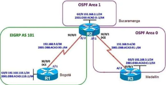
Una empresa de confecciones posee tres sucursales distribuidas en las ciudades de Bogotá, Medellín y Bucaramanga, en donde el estudiante será el administrador de la red, el cual deberá configurar e interconectar entre sí cada uno de los dispositivos que forman parte del escenario, acorde con los lineamientos establecidos para el direccionamiento IP, protocolos de enrutamiento y demás aspectos que forman parte de la topología de red.
Topología de red
Figura 1. Escenario 1
12
Configurar la topología de red, de acuerdo con las siguientes especificaciones.
1.1 PARTE 1: CONFIGURACIÓN DEL ESCENARIO PROPUESTO.
1.1.1 Configurar las interfaces con las direcciones IPv4 e IPv6 que se muestran en la topología de red.
Figura 2. Configuración inicial.
Fuente. Autor del informe
13
Figura 3. Configuración R1
Fuente. Autor del informe
Router(config)#hostname R1 R1(config)#interface s0/0/0
R1(config-if)#ip address 192.168.9.1 255.255.255.252 R1(config-if)#no shutdown
%LINK-5-CHANGED: Interface Serial0/0/0, changed state to down R1(config-if)#int g0/0
R1(config-if)#ip address 192.168.110.1 255.255.255.0 R1(config-if)#no shutdown
R1(config-if)#
%LINK-5-CHANGED: Interface GigabitEthernet0/0, changed state to up R1(config-if)#exit
R1(config)#ipv6 unicast-routing R1(config)#interface s0/0/0
R1(config-if)#ipv6 address 2001:DB8:ACAD:90::1/64 R1(config-if)#IPV6 address FE80::1 link-local
R1(config-if)#no shutdown R1(config-if)#interface g0/0
R1(config-if)#ipv6 address 2011:DB8:ACAD:110::1/64 R1(config-if)#no shutdown
14
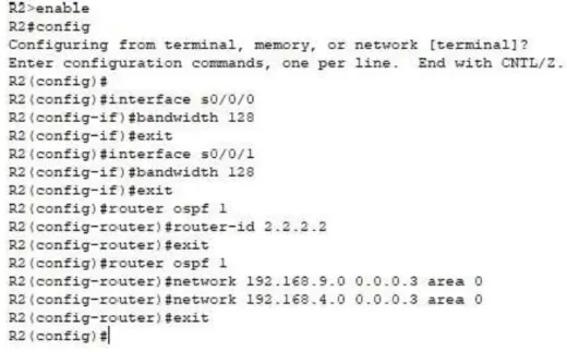
Figura 4. Configuración R2
Fuente. Autor del informe
R2(config)#hostname R2 R2(config)#ipv6 unicast-routing R2(config)#no ip domain-lookup R2(config)#line con 0
R2(config-line)#logging synchronous R2(config-line)#exec-timeout 0 0 R2(config-line)#interface s0/0/0
R2(config-if)#ip address 192.168.9.2 255.255.255.252 R2(config-if)#ipv6 address 2001:db8:acad:90::2/64 R2(config-if)#ipv6 address fe80::2 link-local
R2(config-if)#no shutdown R2(config-if)#exit
R2(config)#interface s0/0/1
R2(config-if)#ip address 192.168.9.5 255.255.255.252 R2(config-if)#ipv6 address 2001:db8:acad:91::1/64 R2(config-if)#ipv6 address fe80::2 link-local
R2(config-if)#no shutdown R2(config-if)#exit
R2(config)#interface g0/0
15
R2(config-if)#ipv6 address 2001:db8:acad:b::1/64 R2(config-if)#no shutdown
R2(config-if)#exir ^
% Invalid input detected at '^' marker. R2(config-if)#exit
R2(config)#
%LINK-5-CHANGED: Interface Serial0/0/0, changed state to up
%LINEPROTO-5-UPDOWN: Line protocol on Interface Serial0/0/0, changed state to up
Figura 5. Configuración R3
16
enable conf t
hostname R3 ipv6 unicast-routing no ip domain-lookup line con 0
logging synchronous exec-timeout 0 0 exit
interface s0/0/1
ip address 192.168.9.6 255.255.255.252 ipv6 address 2001:db8:acad:91::2/64 ipv6 address fe80::3 link-local
no shutdown exit
interface g0/0 9
ip address 192.168.3.1 255.255.255.0 ipv6 address 2001:db8:acad:c::1/64 no shutdown
exit
Topología luego de realizar la configuración de las interfaces en el Router R1, R2 y R3.
Figura 6. Simulación de escenario 1.
17
1.1.2 Ajustar el ancho de banda a 128 kbps sobre cada uno de los enlaces
seriales ubicados en R1, R2, y R3 y ajustar la velocidad de reloj de las conexiones de DCE según sea apropiado.
Para configurar los elementos de ancho de banda a 128 kbps sobre cada uno de los enlaces seriales en R1, R2 y R3y ajustar la velocidad del reloj se realizan los siguientes comandos:
R1
R1(config)#interface s0/0/0 R1(config-if)#bandwidth 128 R1(config-if)#clock rate 128000 R1(config-if)#no shutdown R1(config-if)#
R2
R2#configure
Configuring from terminal, memory, or network [terminal]? Enter configuration commands, one per line. End with CNTL/Z. R2(config)#interface s0/0/0 R2(config-if)#bandwidth 128 R2(config-if)#no shutdown R2(config-if)#exit R2(config)#interface s0/0/1 R2(config-if)#bandwidth 128 R2(config-if)#clock rate 128000 R2(config-if)#no shutdown R2(config-if)#exit
R2(config)#!
R3
R3#config
Configuring from terminal, memory, or network [terminal]? Enter configuration commands, one per line. End with CNTL/Z. R3(config)#interface s0/0/1
R3(config-if)#bandwidth 128 R3(config-if)#no shutdown R3(config-if)#exit
18
1.1.3 En R2 y R3 configurar las familias de direcciones OSPFv3 para IPv4 e IPv6. Utilice el identificador de enrutamiento 2.2.2.2 en R2 y 3.3.3.3 en R3 para ambas familias de direcciones.
Dado que OSPFv3 es el equivalente a OSPFv2 para intercambiar prefijos IPv6, puesto que en IPv6, la dirección de red se denomina “prefijo” y la máscara de subred se denomina “longitud de prefijo”. Se realiza la configuración de OSPF a partir de que el comportamiento predeterminado de OSPF para las interfaces debe anunciar una ruta de host de 32 bits.
R2
R2(config-router)#exit R2(config)#router ospf 1
R2(config-router)#router-id 2.2.2.2 R2(config-router)#exit
R2(config)#
R3
R3(config)#
R3(config)#router ospf 1
R3(config-router)#router-id 3.3.3.3 R3(config-router)#exit
R3(config)#
En R2, configurar la interfaz F0/0 en el área 1 de OSPF y la conexión serial entre R2 y R3 en OSPF área 0.
En este ejemplo, el R2, está conectado con R1 y el R3 a través de una interfaz serial y configurados. El r2 del Routers y el R3 comunican con su r1 de los routers locales y R1 usando OSPFv3. Los Loopback Address se crean en el Routers para generar las redes. El r2 del Routers y el R3, que ejecutan SPFv3, utilizan el comando redis|tribute para redistribuir las rutas OSPFv3.
19
Figura 7. Conexión serial entre R2 y R3 en OSPF área 0 en R2.
Fuente. Autor del informe
1.1.4 En R3, configurar la interfaz F0/0 y la conexión serial entre R2 y R3 en OSPF área 0.
Figura 8. Conexión serial entre R2 y R3 en OSPF área 0 en R3.
20
1.1.5 Configurar el área 1 como un área totalmente Stubby.
Esta área es propietaria de Cisco, esto quiere decir que no acepta rutas de otros tipos de sistemas externos o rutas sumarizadas desde otras áreas internas. Al igual que en las áreas Stub, los routers se encargan de enviar una ruta por defecto para todas las rutas externas y SUMARIZADAS. A continuación, se muestra la manera de configurarla con tres simples códigos.
1.1.6 Propagar rutas por defecto de IPv4 y IPv6 en R3 al interior del dominio OSPFv3.
Teniendo en cuenta que OSPF es un protocolo de enrutamiento dinámico, dentro del cual se desvincula uno de los protocolos IGP (Interior Gateway Protocol), este, utiliza el estado de los enlaces para crear un mapa en la tabla de enrutamiento y determinar la mejor ruta para los paquetes. Para configurar este en modo por defecto en IPv4 y IPv6 basta con ingresar al modo privilegiado del área e ingresar los códigos que se muestran en la imagen.
1.1.7 Realizar la configuración del protocolo EIGRP para IPv4 como IPv6. Configurar la interfaz F0/0 de R1 y la conexión entre R1 y R2 para EIGRP con el sistema autónomo 101. Asegúrese de que el resumen automático está desactivado.
El protocolo Enhanced Interior Gateway Protocol (EIGRP) es un protocolo propietario de Cisco, esto significa que es exclusivo para redes Cisco. EIGRP es un protocolo híbrido ya que tiene características de protocolos de enrutamiento Vector Distancia (Distance Vector) y Estado de Enlace (Link State). Tecnicamente e EIGRP, utiliza el Vector Distancia y realiza la 18 actualización de la tabla de enrutamiento cada 90 segundos (Update Timer) y establece relaciones de adyacencia entre los routers
21 Fuente. Autor del informe
Figura 10. Configuración conexión entre R1 y R2 para EIGRP con el sistema autónomo 101.
Fuente. Autor del informe
1.1.8 Configurar las interfaces pasivas para EIGRP según sea apropiado.
22
1.1.10 En R2, de hacer publicidad de la ruta 192.168.3.0/24 a R1 mediante una lista de distribución y ACL.
Figura 11. Publicidad de la ruta 192.168.3.0/24 a R1 mediante una lista de distribución y ACL.
Fuente. Autor del informe
1.2 PARTE 2: VERIFICAR CONECTIVIDAD DE RED Y CONTROL DE LA TRAYECTORIA.
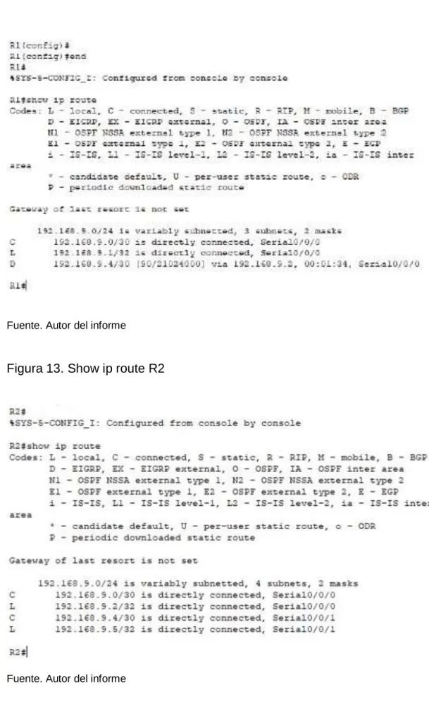
1.2.1 Registrar las tablas de enrutamiento en cada uno de los routers, acorde con los parámetros de configuración establecidos en el escenario propuesto.
23 Fuente. Autor del informe
Figura 13. Show ip route R2
24
Figura 14. Show ip route R3
Fuente. Autor del informe
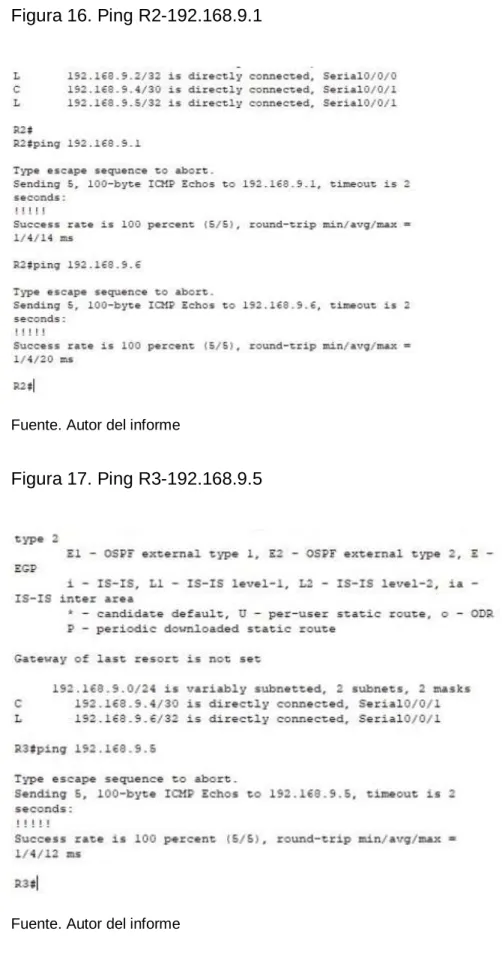
1.2.2 Verificar comunicación entre routers mediante el comando ping y traceroute.
Figura 15. Ping R1-192.168.9.2
25
Figura 16. Ping R2-192.168.9.1
Fuente. Autor del informe
Figura 17. Ping R3-192.168.9.5
26
1.2.3 Verificar que las rutas filtradas no están presentes en las tablas de enrutamiento de los routers correctas.
27
2. ESCENARIO 2
Una empresa de comunicaciones presenta una estructura Core acorde a la topología de red, en donde el estudiante será el administrador de la red, el cual deberá configurar e interconectar entre sí cada uno de los dispositivos que forman parte del escenario, acorde con los lineamientos establecidos para el direccionamiento IP, etherchannels, VLANs y demás aspectos que forman parte del escenario propuesto.
Topología de red
Figura 18. Escenario 2
Fuente. Autor del informe
2.1 PARTE 1: CONFIGURAR LA RED DE ACUERDO CON LAS ESPECIFICACIONES.
28
Figura 19. Configuración inicial
Fuente. Autor del informe
a. Apagar todas las interfaces en cada switch.
29
Figura 20. Configuración inicial DLS1
30
c. Configurar los puertos troncales y Port-channels tal como se muestra en el diagrama.
1) La conexión entre DLS1 y DLS2 será un EtherChannel capa-3 utilizando LACP. Para DLS1 se utilizará la dirección IP 10.12.12.1/30 y para DLS2 utilizará 10.12.12.2/30.
2) Los Port-channels en las interfaces Fa0/7 y Fa0/8 utilizarán LACP. 3) Los Port-channels en las interfaces F0/9 y fa0/10 utilizará PAgP.
4) Todos los puertos troncales serán asignados a la VLAN 800 como la VLAN nativa.
d. Configurar DLS1, ALS1, y ALS2 para utilizar VTP versión 3
Figura 21. DLS1 VLAN800 – VTP Version3
Fuente. Autor del informe
31
Figura 22. ALS1
Fuente. Autor del informe
Figura 23. DLS1
32
Figura 24. ALS2
Fuente. Autor del informe
2) Configurar DLS1 como servidor principal para las VLAN. 3) Configurar ALS1 y ALS2 como clientes VTP.
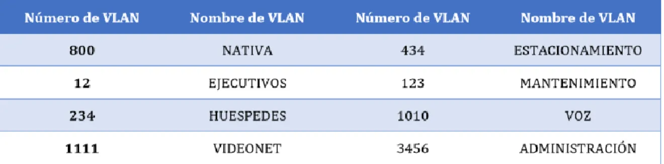
e. Configurar en el servidor principal las siguientes VLAN:
Tabla 1. Configuración VLAN
33
Figura 25. Configuración VLAN DLS1
Fuente. Autor del informe
f. En DLS1, suspender la VLAN 434.
Figura 26. Suspensión VLAN 434 en DLS1
34
g. Configurar DLS2 en modo VTP transparente VTP utilizando VTP versión 2, y configurar en DLS2 las mismas VLAN que en DLS1.
Figura 27. Configuración DLS2 en modo VTP transparente VTP utilizando VTP versión 2
Fuente. Autor del informe
35
Figura 28. Suspensión VLAN 434 en DLS2
Fuente. Autor del informe
i. En DLS2, crear VLAN 567 con el nombre de CONTABILIDAD. La VLAN de CONTABILIDAD no podrá estar disponible en cualquier otro Switch de la red. j. Configurar DLS1 como Spanning tree root para las VLAN 1, 12, 434, 800,
1010, 1111 y 3456 y como raíz secundaria para las VLAN 123 y 234.
Figura 29. Configuración DLS1 como Spanning tree root
36
Figura 30. VLAN 567 Down
Fuente. Autor del informe
k. Configurar DLS2 como Spanning tree root para las VLAN 123 y 234 y como una raíz secundaria para las VLAN 12, 434, 800, 1010, 1111 y 3456.
Figura 31. DLS2 como Spanning tree root
37
l. Configurar todos los puertos como troncales de tal forma que solamente las VLAN que se han creado se les permitirá circular a través de estos puertos. m. Configurar las siguientes interfaces como puertos de acceso, asignados a las
VLAN de la siguiente manera:
Figura 32. Configuración todos los puertos como troncales
Fuente. Autor del informe
Tabla 2. Configuración de interfaces como puertos de acceso
38
Figura 33. Configuración puerto de acceso DLS2
Fuente. Autor del informe
2.2. PARTE 2: CONECTIVIDAD DE RED DE PRUEBA Y LAS OPCIONES CONFIGURADAS.
a. Verificar la existencia de las VLAN correctas en todos los switches y la asignación de puertos troncales y de acceso
b. Verificar que el EtherChannel entre DLS1 y ALS1 está configurado correctamente.
39
Figura 34. Show vlan DLS1
Fuente. Autor del informe
Figura 35. Show vlan DLS2
40
Figura 36. Puertos
41
Figura 37. Simulación escenario 2
Fuente. Autor del informe
Comandos ingresados:
DLS1
en conf t
hostname DLS1 int ran f0/1-24, g0/1-2 shutdown
exit
int ran f0/11-12 no switchport
channel-group 12 mode active no shut
exit
interface port-channel 12
ip address 10.12.12.1 255.255.255.252 exit
int ran f0/7-10
switchport trunk encapsulation dot1q switchport trunk NATIVA vlan 800 switchport mode trunk
42
exit
int ran f0/7-8
channel-group 1 mode active exit
int ran f0/9-10
channel-group 4 mode desirable exit
vtp domain UNAD vtp ver 3
vtp password cisco123 end
! !
vtp primary vlan ! ! conf t vlan 800 name NATIVA exit vlan 434 name ESTACIONAMIENTO state suspend exit vlan 12 name EJECUTIVOS exit vlan 123 name MANTENIMIENTO exit vlan 234 name HUESPEDES exit vlan 1010 name VOZ exit vlan 1111 name VIDEONET exit vlan 3456 name MANAGEMENT exit
43
spanning-tree vlan 123,234 root secondary interface port-channel 1
switchport trunk allowed vlan 12,123,234,800,1010,1111,3456 exit
interface port-channel 4 switchport trunk allowed vlan 12,123,234,800,1010,1111,3456 ip routing
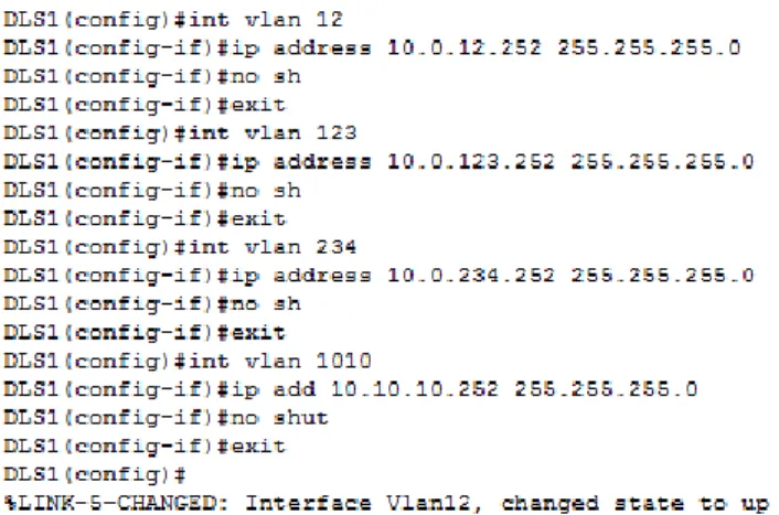
ipv6 unicast-routing int vlan 12
ip address 10.0.12.252 255.255.255.0 no sh
exit
int vlan 123
ip address 10.0.123.252 255.255.255.0 no sh
exit
int vlan 234
ip address 10.0.234.252 255.255.255.0 no sh
exit
int vlan 1010
ip add 10.10.10.252 255.255.255.0 no shut
exit
int vlan 1111
ip add 10.11.11.252 255.255.255.0 no sh
exit
int vlan 3456
ip address 10.34.56.252 255.255.255.0 no shut
exit int loop 0
ip address 1.1.1.1 255.255.255.255 no shut
exit !
interface f0/6 switchport host
switchport access vlan 3456 no shut
44
swi host swi ac v 1111 no sh
exit
int ran f0/1-5, f0/13-14, f0/16-24, g0/1-2 swi host
swi ac v 434 shut
exit !
int vlan 12 standby ver 2
standby 1 ip 10.0.12.254 standby 1 preempt standby 1 priority 110 standby 1 track loop 0 30 exit
int vlan 123 stand ver 2
stand 2 ip 10.0.123.254 standby 2 preempt exit
int vlan 234 stand ver 2
stand 2 ip 10.0.234.254 stand 2 preempt
exit
int vlan 1010 stand ver 2
stand 1 ip 10.10.10.254 stand 1 preempt
stand 1 pri 110
standby 1 track loop 0 30 exit
int vlan 1111 stand ver 2
stand 1 ip 10.11.11.254 stand 1 preempt
stand 1 pri 110
standby 1 track loop 0 30 exit
45
stand 1 ip 10.34.56.254 stand 1 preempt
stand 1 pri 110
standby 1 track loop 0 30 exit
! ! !
ip dhcp pool EJECUTIVOS-POOL network 10.0.12.0 255.255.255.0 default-router 10.0.12.254
dns-server 1.1.1.1 exit
ip dhcp pool MANTENIMIENTO-POOL network 10.0.123.0 255.255.255.0 default-router 10.0.123.254
dns-server 1.1.1.1 exit
ip dhcp pool HUESPEDES-POOL network 10.0.234.0 255.255.255.0 default-router 10.0.234.254 dns-server 1.1.1.1 exit DLS2 en conf t
int ran f0/1-24, g0/1-2 shutdown
exit
int ran f0/11-12 no switchport
channel-group 12 mode active no shut
exit
interface port-channel 12
ip address 10.12.12.2 255.255.255.252 exit
int ran f0/7-10
switchport trunk encapsulation dot1q switchport trunk NATIVA vlan 800 switchport mode trunk
46
exit
int ran f0/7-8
channel-group 2 mode active exit
int ran f0/9-10
channel-group 3 mode desirable exit
vtp ver 2
vtp mode transparent
spanning-tree vlan 1,12,123,234,434,800,1010,3456 root secondary
spanning-tree vlan 123,234 root primary vlan 800 name NATIVA-VLAN exit vlan 434 name ESTACIONAMIENTO-LOT state suspend exit vlan 12 name EJECUTIVOS exit vlan 123 name MANTENIMIENTO exit vlan 234 name HUESPEDES exit vlan 1010 name VOZ exit vlan 1111 name VIDEONET exit vlan 3456 name MANAGEMENT exit vlan 567 name ACCOUNTING exit
47
interface port-channel 3 switchport trunk allowed vlan 12,123,234,800,1010,1111,3456 exit
ip routing
ipv6 unicast-routing int vlan 12
ip address 10.0.12.253 255.255.255.0 no sh
exit
int vlan 123
ip address 10.0.123.253 255.255.255.0 no sh
exit
int vlan 234
ip address 10.0.234.253 255.255.255.0 no sh
exit
int vlan 1010
ip add 10.10.10.253 255.255.255.0 no shut
exit
int vlan 1111
ip add 10.11.11.253 255.255.255.0 no shut
exit
int vlan 3456
ip address 10.34.56.253 255.255.255.0 no shut
exit int loop 0
ip address 1.1.1.1 255.255.255.255 no shut
exit !
interface f0/6 switchport host
switchport access vlan 12 switchport VOZ vlan 1010 no shut
48
exit
int ran f0/16-18 swi host
swi ac v 567 no shut exit
int ran f0/1-5, f0/13-14, f0/19-24, g0/1-2 swi host
swi ac v 434 shut
exit ! !
int vlan 12 standby ver 2
standby 1 ip 10.0.12.254 standby 1 preempt exit
int vlan 123 stand ver 2
stand 2 ip 10.0.123.254 standby 2 preempt standby 2 priority 110 standby 2 track loop 0 30 exit
int vlan 234 stand ver 2
stand 2 ip 10.0.234.254 stand 2 preempt
standby 2 priority 110 standby 2 track loop 0 30 exit
int vlan 1010 stand ver 2
stand 1 ip 10.10.10.254 stand 1 preempt
exit
int vlan 1111 stand ver 2
stand 1 ip 10.11.11.254 stand 1 preempt
exit
int vlan 3456 stand ver 2
49
stand 1 preempt exit ! ! ALS1 en conf t hostname ALS1 int ran f0/1-24, g0/1-2 shutdown
exit
int ran f0/7-10 swi mo tru swi tr nat v 800 swi non
no shut exit
int ran f0/7-8
channel-group 1 mode active switchport trunk allowed vlan 12,123,234,800,1010,1111,3456 no shut
exit
int ran f0/9-10
channel-group 3 mode desirable switchport trunk allowed vlan 12,123,234,800,1010,1111,3456 no shut
exit
int vlan 3456
ip address 10.34.56.101 255.255.255.0 no shut
exit
ip default-gateway 10.34.56.254 vtp domain UNAD
vtp ver 3 vtp mo client
vtp password cisco123 !
! int f0/6
switchport host
50
switchport VOZ vlan 1010 no shut
exit int f0/15 swi host swi ac v 1111 no sh
exit
int ran f0/1-5, f0/13-14, f0/16-24, g0/1-2 swi host
swi ac v 434 shut exit ALS2 en conf t hostname ALS2 int ran f0/1-24, g0/1-2 shutdown
exit
int ran f0/7-10 swi mo tru swi tr nat v 800 swi non
no shut exit
int ran f0/7-8
channel-group 2 mode active switchport trunk allowed vlan 12,123,234,800,1010,1111,3456 no shut
exit
int ran f0/9-10
channel-group 4 mode desirable switchport trunk allowed vlan 12,123,234,800,1010,1111,3456 no shut
exit
int vlan 3456
ip add 10.34.56.102 255.255.255.0 no shut
exit
51
vtp ver 3 vtp mo client
vtp password cisco123 !
! int f0/6
switchport host
switchport access vlan 234 no shut
exit int f0/15 swi host swi ac v 1111 no sh
exit
int ran f0/1-5, f0/13-14, f0/16-24, g0/1-2 swi host
swi ac v 434 shut
52
3. CONCLUSIONES
Este trabajo escrito da cumplimiento al objetivo de habilidades practicas del diplomado de profundización en redes Cisco Networking, y de la misma forma como trabajo de grado para obtener el título de ingeniero electrónico de la universidad Nacional Abierta y a distancia UNAD.
Trabajamos sobre dos topologías de redes con diferentes exigencias de conexión y condiciones de implementación, las cuales quedaran plasmadas en este trabajo, por medio de la simulación en el software packet tracer, el cual está diseñado para el trabajo de redes con router’s y switches de la tecnología Cisco.
Este trabajo representa la aplicación de los conocimientos adquiridos durante el transcurso del curso, se pudo evidenciar como el Switching y el Routing permiten aumentar la velocidad de acceso a la información, para administrar esta de manera eficiente y verificar lo que acontece en la empresa donde funciona gracias a la implementación de protocolos de enrutamiento como lo son EIGRP Y OSPF, además se utilizaron VLAN, las cuales son bastante útiles al momento de proteger la red implementada, por otra parte el protocolo spanning tree, permite garantizar que no se creen loops cuando se tengan trayectorias redundantes en la red, ya que los loops son fatales para una red.
Por medio del diplomado de profundización se adquieren conocimientos más concretos y enfáticos sobre el Routing and Switching en la tecnología de redes CISCO, por medio de la profundización se interactúa con plataformas simuladoras en implementación de redes, donde se realizan las pruebas y laboratorios requeridos en el diplomado.
53
4. REFERENCIAS BIBLIOGRAFICAS
Teare, D., Vachon B., Graziani, R. (2015). CISCO Press (Ed). Basic Network and Routing Concepts. Implementing Cisco IP Routing (ROUTE) Foundation Learning Guide CCNP ROUTE 300-101. Recuperado de https://1drv.ms/b/s!AmIJYei-NT1IlnMfy2rhPZHwEoWx
UNAD (2015). Introducción a la configuración de Switches y Routers [OVA]. Recuperado de https://1drv.ms/u/s!AmIJYei-NT1IhgL9QChD1m9EuGqC
Macfarlane, J. (2014). Network Routing Basics: Understanding IP Routing in Cisco Systems. Recuperado de
http://bibliotecavirtual.unad.edu.co:2048/login?url=http://search.ebscohost.com/logi n.aspx?direct=true&db=e000xww&AN=158227&lang=es&site=ehost-live
Wallace, K. (2015). CISCO Press (Ed). CCNP Routing and Switching ROUTE
300-101 Official Cert Guide. Recuperado de
https://1drv.ms/b/s!AgIGg5JUgUBthFx8WOxiq6LPJppl
Donohue, D. (2017). CISCO Press (Ed). CCNP Quick Reference. Recuperado de
https://1drv.ms/b/s!AgIGg5JUgUBthFt77ehzL5qp0OKD
Spanning Tree Implementation Froom, R., Frahim, E. (2015). CISCO Press (Ed). Spanning Tree Implementation. Implementing Cisco IP Switched Networks (SWITCH) Foundation Learning Guide CCNP SWITCH 300-115. Recuperado de
https://1drv.ms/b/s!AmIJYei-NT1IlnWR0hoMxgBNv1CJ
Froom, R., Frahim, E. (2015). CISCO Press (Ed). High Availability. Implementing Cisco IP Switched Networks (SWITCH) Foundation Learning Guide CCNP SWITCH 300-115. Recuperado de https://1drv.ms/b/s!AmIJYeiNT1IlnWR0hoMxgBNv1CJ
Froom, R., Frahim, E. (2015). CISCO Press (Ed). First Hop Redundancy Protocols. Implementing Cisco IP Switched Networks (SWITCH) Foundation Learning Guide CCNP SWITCH 300-115. Recuperado de
54
Fundamentals Review Froom, R., Frahim, E. (2015). CISCO Press (Ed). Fundamentals Review. Implementing Cisco IP Switched Networks (SWITCH) Foundation Learning Guide CCNP SWITCH 300-115. Recuperado de
https://1drv.ms/b/s!AmIJYei-NT1IlnWR0hoMxgBNv1CJ