1
Diplomado de Profundización Cisco (Diseño e Implementación de Soluciones Integradas LAN / WAN)
Actividad Colaborativa Unidad 4 Grupo 203092_25
Realizado por:
Edgar Jovanny Larrota Daniel Eduardo Cáceres
Jullian Paola Villalobos Rafael Antonio Quiroga García
Lady Alejandra Gómez Torres
Presentado a:
Martha Fabiola Contreras Higuera
Universidad Nacional Abierta y a Distancia (UNAD) Escuela de Ciencias Básicas Tecnología e Ingeniería - ECBTI
2
Contenido
Introducción ... 4
Objetivos ... 5
Ejercicio 4.4.1.2 ... 6
Part 2: Secure Access to Routers ... 10
Part 3: Create a Numbered IP ACL 120 on R1 ... 14
Part 4: Modify An Existing ACL on R1 ... 16
Part 5: Create a Numbered IP ACL 110 on R3 ... 18
Ejercicio 7.3.2.1 ... 2
Ejercicio 8.2.4.5 ... 15
Ejercicio 8.3.3.6 ... 37
Ejercicio 9.2.1.10 ... 56
Part 1: Plan an ACL Implementation ... 57
Resultados ... 62
Ejercicio 9.2.1.11 ... 63
Topology ... 63
Part1: Configure and Apply a Named StandardACL ... 64
Step 3: Apply the namedACL. ... 66
Part2: Verify the ACL Implementation ... 66
Step 1: Verify the ACL configuration and application to the interface... 66
Step 2: Verify that the ACL is workingproperly... 68
Ejercicio 9.2.3.3 ... 70
Packet tracer – Configuring an ACL ON VTYLINES ... 70
Part 1: Configure and Apply an ACL to VTY Lines ... 71
Part 2: Verify the ACL Implementation ... 72
Ejercicio 9.2.1.11 ... 74
9.5.2.6 Packet Tracer – Configuring -IPV6ACLS ... 74
Part 1: Configure, Apply, and Verify an IPv6 ACL ... 75
Step 2: Apply the ACL to the correct interface... 75
Part 2: Configure, Apply, and Verify a Second IPv6 ACL ... 77
3
Parte 1: armar la red y configurar los parámetros básicos de los dispositivos………82
Parte 2: configurar un servidor de DHCPv4 y un agente de retransmisión DHCP ... 88
Ejercicio 10.1.2.5 ... 96
Armar la red y configurar los parámetros básicos de los dispositivos ... 98
Cambiar la preferencia de SDM ... 100
Configurar DHCPv4 ... 102
Configurar DHCPv4 para varias VLAN ... 105
Habilitar el routing IP ... 107
Reflexión ... 112
Ejercicio 10.2.3.5 ... 113
Armar la red y configurar los parámetros básicos de los dispositivos ... 115
Configurar la red para SLAAC ... 117
Configurar la red para DHCPv6 sin estado ... 123
Configurar la red para DHCPv6 con estado ... 129
Reflexión ... 138
Ejercicio 10.3.1.1 ... 140
Reflexión ... 141
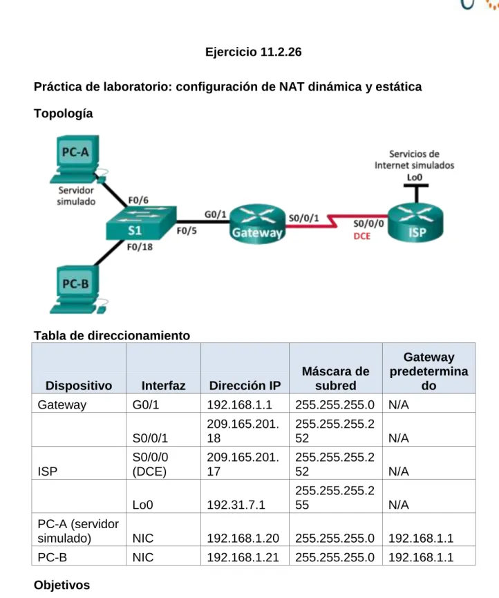
Ejercicio 11.2.26 ... 142
Armar la red y verificar la conectividad ... 143
Configurar y verificar la NAT estática. ... 150
Configurar y verificar la NAT dinámica ... 154
Reflexión ... 159
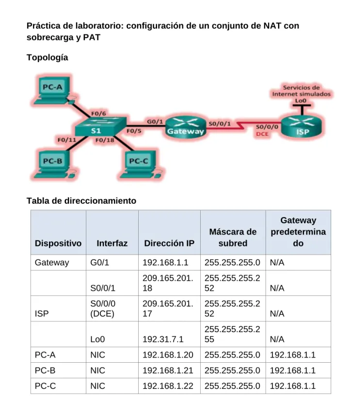
Ejercicio 11.2.3.7 ... 161
Armar la red y verificar la conectividad ... 163
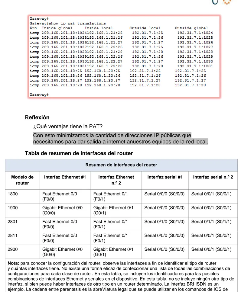
Configurar y verificar el conjunto de NAT con sobrecarga ... 166
Configurar y verificar PAT ... 171
Reflexión ... 174
Conclusiones ... 175
4
Introducción
El presente trabajo pretende profundizar en aspectos de diseño e implementación de soluciones integradas LAN / WAN, orientándonos a realizar configuraciones, conocer e implementar protocolos y estándares de seguridad; acorde a las instalaciones de redes que se implementen y teniendo presente las normas establecidas que el Cisco exige, ya sea a nivel empresarial o personal. Lo anterior con el fin de obtener instalaciones seguras y adquirir conocimientos pertinentes para la protección de este tipo de redes.
De acuerdo al laboratorio propuesto se incorporó diversas etapas para alcanzar la solución de las actividades y los objetivos planteados, considerando básicamente:
1. Comprender el punto de partida; de cómo el grupo colaborativo visualizo e interpretó el problema, la necesidad o la motivación para la adquisición de los temas a desarrollar.
2. Búsqueda de recursos que nos diera una concepción adecuada de información previa a su desarrollo.
3. Realización de los procedimientos e implementación del software Packet Tracer
Entre los resultados que pretendemos conseguir con este Ejercicio y que aplican a la parte práctica, está en conocer la planificación y ejecución de proyectos similares en redes integradas LAN / WAN, que nos permita identificar las principales dificultades, sus ventajas, las posibles mejoras de elaboración, e impactos, establecer la utilidad, los costos y beneficios e identificar parámetros de diseño y optimización. Y a nivel personal en el mejoramiento de nuestro desarrollo personal y profesional, el cual consiste en brindar soluciones tecnológicas innovadoras para satisfacer las necesidades y problemáticas derivadas hacia este tipo de alternativas.
En esta unidad se abarcan varias temáticas que aplican al desarrollo de las actividades propuestas para este, continuando con la herramienta PacketTracer.
5
Objetivos
Objetivo General
Desarrollar destreza y conocimientos relacionados a la construcción y protección de la Redes LAN / WAN.
Objetivos Específicos
- Adquirir conceptos básicos para implementar configuraciones en una red
- Conocer los componentes necesarios para instalar redes sencillas inicialmente
6
Ejercicio 4.4.1.2
Packet Tracer - Configure IP ACLs to Mitigate Attacks
Addressing Table
Device Interface IPAddress Subnet Mask DefaultGateway SwitchPort
R1
Fa0/1 192.168.1.1 255.255.255.0 N/A S1 Fa0/5
S0/0/0 (DCE) 10.1.1.1 255.255.255.252 N/A N/A
R2
S0/0/0 10.1.1.2 255.255.255.252 N/A N/A
S0/0/1 (DCE) 10.2.2.2 255.255.255.252 N/A N/A
Lo0 192.168.2.1 255.255.255.0 N/A N/A
R3
Fa0/1 192.168.3.1 255.255.255.0 N/A S3 Fa0/5
S0/0/1 10.2.2.1 255.255.255.252 N/A N/A
PC-A NIC 192.168.1.3 255.255.255.0 192.168.1.1 S1 Fa0/6
PC-C NIC 192.168.3.3 255.255.255.0 192.168.3.1 S3 Fa0/18
Objetives
Verify connectivity among devices before firewall configuration.
Use ACLs to ensure remote access to the routers is available only from management station PC-C.
Configure ACLs on R1 and R3 to mitigate attacks. Verify ACL functionality.
Background / Scenario
7
Standard operating procedure is to apply ACLs on edge routers to
mitigate common threats based on source and/or destination IP address.
In this activity, you create ACLs on edge routers R1 and R3 to achieve this goal. You then verify ACL functionality from internal and external hosts.
The routers have been pre-configured with the following: Enable password: ciscoenpa55
Password for console: ciscoconpa55 Username for VTY lines: SSHadmin Password for VTY lines: ciscosshpa55 IP addressing
Static routing
Part 1: Verify Basic Network Connectivity
Verify network connectivity prior to configuring the IP ACLs.
Step1: From PC-A, verify connectivity to PC-C andR2. From the command prompt, ping PC-C(192.168.3.3).
From the command prompt, establish a SSH session to R2 Lo0 interface (192.168.2.1) using username
8
Step2: From PC-C, verify connectivity to PC-A andR2. From the command prompt, ping PC-A(192.168.1.3).
From the command prompt, establish a SSH session to R2 Lo0 interface (192.168.2.1) using username
9
10
Part 2: Secure Access to Routers
Step1: Configure ACL 10 to block all remote access to the routers except fromPC-C.
Use the access-list command to create a numbered IP ACL on R1, R2, and R3. R1(config)# access-list 10 permit 192.168.3.3 0.0.0.0
R2(config)# access-list 10 permit 192.168.3.3 0.0.0.0
11
Step2: Apply ACL 10 to ingress traffic on the VTYlines.
Use the access-class command to apply the access list to incoming traffic on the VTY lines.
R1(config-line)# access-class 10 in
12 R3(config-line)# access-class 10 in
Step3: Verify exclusive access from management stationPC-C.
13
Step3: Verify exclusive access from management stationPC-C.
Establish a SSH session to 192.168.2.1 from PC-C (should besuccessful). PC> ssh –l SSHadmin 192.168.2.1
14
Part 3: Create a Numbered IP ACL 120 on R1
Permit any outside host to access DNS, SMTP, and FTP services on server PC-A, deny any outside host access to HTTPS services on PC-A, and permit PC-C to access R1 via SSH.
Step1: Verify that PC-C can access the PC-A via HTTPS using the webbrowser. Be sure to disable HTTP and enable HTTPS on server PC-A.
15
Use the access-list command to create a numbered IP ACL.
R1(config)# access-list 120 permit udp any host 192.168.1.3 eq domain R1(config)# access-list 120 permit tcp any host 192.168.1.3 eq smtp R1(config)# access-list 120 permit tcp any host 192.168.1.3 eq ftp R1(config)# access-list 120 deny tcp any host 192.168.1.3 eq 443
R1(config)# access-list 120 permit tcp host 192.168.3.3 host 10.1.1.1 eq22
Step3: Apply the ACL to interfaceS0/0/0.
Use the ip access-group command to apply the access list to incoming traffic on interface S0/0/0.
R1(config)# interface s0/0/0
16
Step4: Verify that PC-C cannot access PC-A via HTTPS using the webbrowser.
Part 4: Modify An Existing ACL on R1
Permit ICMP echo replies and destination unreachable messages from the outside network (relative to R1); deny all other incoming ICMP packets.
17
Step2: Make any necessary changes to ACL 120 to permit and deny the specified traffic.
Use the access-list command to create a numbered IP ACL. R1(config)# access-list 120 permit icmp any any echo-reply R1(config)# access-list 120 permit icmp any any unreachable R1(config)# access-list 120 deny icmp any any
R1(config)# access-list 120 permit ip any any
18
Part 5: Create a Numbered IP ACL 110 on R3
Deny all outbound packets with source address outside the range of internal IP addresses on R3.
Step1: Configure ACL 110 to permit only traffic from the inside network. Use the access-list command to create a numbered IP ACL.
R3(config)# access-list 110 permit ip 192.168.3.0 0.0.0.255 any Step2: Apply the ACL to interfaceF0/1.
Use the ip access-group command to apply the access list to incoming traffic on interface F0/1.
R3(config)# interface fa0/1
R3(config-if)# ip access-group 110 in
Part 6: Create a Numbered IP ACL 100 on R3
On R3, block all packets containing the source IP address from the following pool of addresses: 127.0.0.0/8, any RFC 1918 private addresses, and any IP multicast address.
Step1: Configure ACL 100 to block all specified traffic from the outsidenetwork. You should also block traffic sourced from your own internal address space if it is not an RFC 1918 address (in this activity, your internal address space is part of the private address space specified in RFC 1918).
19
R3(config)# access-list 100 deny ip 172.16.0.0 0.15.255.255 any R3(config)# access-list 100 deny ip 192.168.0.0 0.0.255.255 any R3(config)# access-list 100 deny ip 127.0.0.0 0.255.255.255 any R3(config)# access-list 100 deny ip 224.0.0.0 15.255.255.255 any R3(config)# access-list 100 permit ip any any
Step2: Apply the ACL to interface Serial0/0/1.
Use the ip access-group command to apply the access list to incoming traffic on interface Serial 0/0/1.
R3(config)# interface s0/0/1
20
Step3: Confirm that the specified traffic entering interface Serial 0/0/1 is dropped. From the PC-C command prompt, ping the PC-A server. The ICMP echo replies
are blocked by the ACL since they are sourced from the 192.168.0.0/16 address space.
Step4: Check results.
21 !!!Script for R1
access-list 10 permit 192.168.3.3 0.0.0.0 line vty 0 4 access-class 10 in
access-list 120 permit udp any host 192.168.1.3 eq domain access-list 120 permit tcp any host 192.168.1.3 eq smtp access-list 120 permit tcp any host 192.168.1.3 eq ftp access-list 120 deny tcp any host 192.168.1.3 eq 443
access-list 120 permit tcp host 192.168.3.3 host 10.1.1.1 eq 22 interface s0/0/0 ip access-group 120 in
access-list 120 permit icmp any any echo-reply access-list 120 permit icmp any any unreachable access-list 120 deny icmp any any
access-list 120 permit ip any any !!!Script for R2
access-list 10 permit 192.168.3.3 0.0.0.0 line vty 0 4 access-class 10 in
!!!Script for R3
access-list 10 permit 192.168.3.3 0.0.0.0 line vty 0 4 access-class 10 in
access-list 100 deny ip 10.0.0.0 0.255.255.255 any access-list 100 deny ip
172.16.0.0 0.15.255.255 any access-list 100 deny ip 192.168.0.0 0.0.255.255 any access-list 100 deny ip 127.0.0.0 0.255.255.255 any access-list 100 deny ip 224.0.0.0 15.255.255.255 any access-list 100 permit ip any any
interface s0/0/1
ip access-group 100 in
Ejercicio 7.3.2.1
Parte 1: armar la red y configurar los parámetros básicos de los dispositivos
Configuración R3
Configurar los equipos host.
Se realiza la configuración de las computadoras realizando la destinación de las ips correspondientes según su tabla de enrutamiento
Probar la conectividad.
Configurar el enrutamiento RIPv2.
R2# debugiprip
Después de 60 segundos, emita el comando no debugiprip.
¿Qué rutas que se reciben del R3 se encuentran en las actualizaciones RIP? Es la 172.30.30.0/24
172.30.0.0/24 issubnetted, 2 subnets
R 172.30.10.0/24 [120/1] Vía 10.1.1.1, 00:00:03, Serial0/1/0 R 172.30.30.0/24 [120/1] Vía 10.2.2.1, 00:00:07, Serial0/1/1 209.165.201.0/24 isvariablysubnetted, 2 subnets, 2 masks C 209.165.201.0/24 isdirectlyconnected, GigabitEthernet0/0 L 209.165.201.1/32 isdirectlyconnected, GigabitEthernet0/0
Se incluyen ahora las máscaras de las subredes en las actualizaciones de enrutamiento? Si
Configure y redistribuya una ruta predeterminada para el acceso a Internet
¿En qué forma se proporciona la ruta para el tráfico de Internet en la tabla de routing?
Ejercicio 8.2.4.5
R2
R2
Verificar la configuración del protocolo OSPF. R1
Verificar la conectividad de extremo a extremo
Se procede a realizar la siguiente configuración en los 3 routers igual realizando el reset
#show ip proto
R3#show ip protocols
Routing Protocol is "ospf 1"
Outgoing update filter list for all interfaces is not set Incoming update filter list for all interfaces is not set Router ID 192.168.23.2
Number of areas in this router is 1. 1 normal 0 stub 0 nssa Maximum path: 4
Routing for Networks:
192.168.13.1 110 00:11:26 192.168.23.2 110 00:11:26 Distance: (default is 110)
R3#copy
R3#copy run start
Destination filename [startup-config]? Building configuration...
[OK] R3#relo R3#reload
Proceed with reload? [confirm]
System Bootstrap, Version 15.1(4)M4, RELEASE SOFTWARE (fc1) Technical Support: http://www.cisco.com/techsupport
Copyright (c) 2010 by cisco Systems, Inc.
Total memory size = 512 MB - On-board = 512 MB, DIMM0 = 0 MB CISCO1941/K9 platform with 524288 Kbytes of main memory
Main memory is configured to 64/-1(On-board/DIMM0) bit mode with ECC disabled
Readonly ROMMON initialized
program load complete, entry point: 0x80803000, size: 0x1b340 program load complete, entry point: 0x80803000, size: 0x1b340
IOS Image Load Test ___________________
Digitally Signed Release Software
program load complete, entry point: 0x81000000, size: 0x2bb1c58 Self decompressing the image :
################################################################## ######## [OK]
Smart Init is enabled smart init is sizing iomem TYPE MEMORY_REQ
HWIC Slot 0 0x00200000 Onboard devices & buffer pools 0x01E8F000
--- TOTAL: 0x0268F000
Rounded IOMEM up to: 40Mb.
Restricted Rights Legend
Use, duplication, or disclosure by the Government is subject to restrictions as set forth in subparagraph
(c) of the Commercial Computer Software - Restricted Rights clause at FAR sec. 52.227-19 and subparagraph (c) (1) (ii) of the Rights in Technical Data and Computer Software clause at DFARS sec. 252.227-7013.
Cisco Systems, Inc. 170 West Tasman Drive
San Jose, California 95134-1706
Cisco IOS Software, C1900 Software (C1900-UNIVERSALK9-M), Version 15.1(4)M4, RELEASE SOFTWARE (fc2)
Technical Support: http://www.cisco.com/techsupport Copyright (c) 1986-2012 by Cisco Systems, Inc. Compiled Thurs 5-Jan-12 15:41 by pt_team
Image text-base: 0x2100F918, data-base: 0x24729040
This product contains cryptographic features and is subject to United States and local country laws governing import, export, transfer and use. Delivery of Cisco cryptographic products does not imply third-party authority to import, export, distribute or use encryption.
Importers, exporters, distributors and users are responsible for compliance with U.S. and local country laws. By using this product you agree to comply with applicable laws and regulations. If you are unable to comply with U.S. and local laws, return this product immediately.
A summary of U.S. laws governing Cisco cryptographic products may be found at: http://www.cisco.com/wwl/export/crypto/tool/stqrg.html
If you require further assistance please contact us by sending email to [email protected].
Cisco CISCO1941/K9 (revision 1.0) with 491520K/32768K bytes of memory. Processor board ID FTX152400KS
2 Gigabit Ethernet interfaces
2 Low-speed serial(sync/async) network interface(s) DRAM configuration is 64 bits wide with parity disabled. 255K bytes of non-volatile configuration memory.
Press RETURN to get started!
R3> R3>
%LINEPROTO-5-UPDOWN: Line protocol on Interface Serial0/0/1, changed state to up
%LINEPROTO-5-UPDOWN: Line protocol on Interface Serial0/0/0, changed state to up
¿Qué interfaz usa el R3 para enrutarse a la red 192.168.2.0/24? Utiliza la interface r3 la serial 0/0/0
¿Cuál es la métrica de costo acumulado para la red 192.168.2.0/24 en el R3? Lo realiza por la 129
¿El R2 aparece como vecino OSPF en el R1? Si lo muestra
¿El R2 aparece como vecino OSPF en el R3? No lo muestra por lo que no está activado
¿Qué indica esta información?
Lo que indica es que la red está en modo pasiva y por eso su tráfico lo enVía por r3 a r1 y así llega a r2
Cambie la interfaz S0/0/1 en el R2 para permitir que anuncie las rutas OSPF. Registre los comandos utilizados a continuación.
R2>en R2#conf t
Enter configuration commands, one per line. End with CNTL/Z. R2(config)#route os
R2(config)#route ospf 1 R2(config-router)#no pas
R2(config-router)#no passive-interface s0/0/1 R2(config-router)#
01:25:28: %OSPF-5-ADJCHG: Process 1, Nbr 33.33.33.33 on Serial0/0/1 from LOADING to FULL, Loading Done
Vuelva a emitir el comando show ip route en el R3.
¿Qué interfaz usa el R3 para enrutarse a la red 192.168.2.0/24? _________s0/0/1___
¿Cuál es la métrica de costo acumulado para la red 192.168.2.0/24 en el R3 y cómo se calcula? 65 es la métrica. Cambiar las métricas de OSPF
R1
R2# R2#SH
R2#SHow IP rou
R2#SHow IP route ospf
O 192.168.1.0 [110/65] Vía 192.168.12.2, 00:24:43, Serial0/0/0 O 192.168.3.0 [110/65] Vía 192.168.23.2, 00:07:53, Serial0/0/1 192.168.13.0/30 is subnetted, 1 subnets
O 192.168.13.0 [110/128] Vía 192.168.23.2, 00:07:53, Serial0/0/1 [110/128] Vía 192.168.12.2, 00:07:53, Serial0/0/0
R3
GigabitEthernet0/0 is up, line protocol is up Internet address is 192.168.3.1/24, Area 0
Process ID 1, Router ID 33.33.33.33, Network Type BROADCAST, Cost: 1 Transmit Delay is 1 sec, State DR, Priority 1
Designated Router (ID) 33.33.33.33, Interface address 192.168.3.1 No backup designated router on this network
Timer intervals configured, Hello 10, Dead 40, Wait 40, Retransmit 5 Hello due in 00:00:06
Index 1/1, flood queue length 0 Next 0x0(0)/0x0(0)
R1
192.168.2.0 [110/65] Vía 192.168.12.2, 00:27:50, Serial0/0/0 O 192.168.3.0 [110/65] Vía 192.168.13.2, 01:13:11, Serial0/0/1 192.168.23.0/30 is subnetted, 1 subnets
O 192.168.23.0 [110/128] Vía 192.168.12.2, 00:27:50, Serial0/0/0 [110/128] Vía 192.168.13.2, 00:27:50, Serial0/0/1
R1#SHow IP osp
R1#SHow IP ospf int s0/0/0
Serial0/0/0 is up, line protocol is up
Internet address is 192.168.12.2/30, Area 0
Process ID 1, Router ID 11.11.11.11, Network Type POINT-TO-POINT, Cost: 64 Transmit Delay is 1 sec, State POINT-TO-POINT, Priority 0
No designated router on this network
No backup designated router on this network
Timer intervals configured, Hello 10, Dead 40, Wait 40, Retransmit 5 Hello due in 00:00:02
Index 2/2, flood queue length 0 Next 0x0(0)/0x0(0)
Last flood scan length is 1, maximum is 1
Last flood scan time is 0 msec, maximum is 0 msec Neighbor Count is 1 , Adjacent neighbor count is 1 Adjacent with neighbor 3.3.3.3
Suppress hello for 0 neighbor(s) R1#
R1
Incomplete command.
R1(config-router)#auto-cost ref % Incomplete command.
R1(config-router)#aut
R1(config-router)#auto-cost r
R1(config-router)#auto-cost reference-bandwidth 10000 % OSPF: Reference bandwidth is changed.
Please ensure reference bandwidth is consistent across all routers. R1(config-router)#auto-cost reference-bandwidth 1000
R3 R3> R3> R3>en R3#sho
R3#show ip rou
R3#show ip route ospf
O 192.168.1.0 [110/164] Vía 192.168.13.1, 00:16:32, Serial0/0/0 O 192.168.2.0 [110/65] Vía 192.168.23.1, 00:32:41, Serial0/0/1 192.168.12.0/30 is subnetted, 1 subnets
Explique la razón por la que la ruta a la red 192.168.3.0/24 en el R1 ahora atraviesa el R2.
R/ OSPF elegirá la ruta con el menor costo acumulado. Reflexión
¿Por qué es importante controlar la asignación de ID de router al utilizar el protocolo OSPF?
R/ Asignaciones de ID Router controlan el router designado (DR) y BDR (BDR) elección / proceso en una red de acceso múltiple.
¿Por qué el proceso de elección de DR/BDR no es una preocupación en esta práctica de laboratorio?
R/El proceso de elección DR / BDR es sólo un problema en una red múltiple acceso como Ethernet o Frame Relay.
¿Por qué querría configurar una interfaz OSPF como pasiva?
Ejercicio 8.3.3.6
Parte 1: armar la red y configurar los parámetros básicos de los dispositivos Parte 2: configurar y verificar el routing OSPFv3
Configurar el routing OSPFv3
R3
Pinging 2001:DB8:ACAD:A::1 with 32 bytes of data:
Reply from 2001:DB8:ACAD:A::1: bytes=32 time=63ms TTL=255 Reply from 2001:DB8:ACAD:A::1: bytes=32 time=32ms TTL=255 Reply from 2001:DB8:ACAD:A::1: bytes=32 time=0ms TTL=255 Reply from 2001:DB8:ACAD:A::1: bytes=32 time=0ms TTL=255
Verificar vecinos de OSPFv3 R1
R1>en R1#conf t
Enter configuration commands, one per line. End with CNTL/Z. R1(config)#ipv
R1(config)#ipv6 rout
R1(config)#ipv6 router ospf 1
%OSPFv3-4-NORTRID: OSPFv3 process 1 could not pick a router-id,please configure manually
R1(config-rtr)#exit R1(config)#exit R1#
%SYS-5-CONFIG_I: Configured from console by console
R1# R1#conf t
Enter configuration commands, one per line. End with CNTL/Z. R1(config)#ip
R1(config)#ipv R1(config)#ipv6 rou
R1(config)#ipv6 router ospf 1 R1(config-rtr)#rou
R1(config-rtr)#router-id 1.1.1.1 R1(config-rtr)#
R1#
%SYS-5-CONFIG_I: Configured from console by console
R2
R2# R2#conf t
R2(config)#ipv R2(config)#ipv6 rou
R2(config)#ipv6 router ospf 1 R2(config-rtr)#rou R2(config-rtr)#router-id 2.2.2.2 R2(config-rtr)# R3 R3(config-rtr)#exit R3(config)#ip R3(config)#ipv
R3(config)#ipv6 router ospf 1 R3(config-rtr)#rout R3(config-rtr)#router-id 3.3.3.3 R3(config-rtr)# R2 R2# R2#show ipv R2#show ipv6 ospf
Routing Process "ospfv3 1" with ID 2.2.2.2
SPF schedule delay 5 secs, Hold time between two SPFs 10 secs Minimum LSA interval 5 secs. Minimum LSA arrival 1 secs
LSA group pacing timer 240 secs Interface flood pacing timer 33 msecs Retransmission pacing timer 66 msecs
Number of external LSA 0. Checksum Sum 0x000000 Number of areas in this router is 0. 0 normal 0 stub 0 nssa Reference bandwidth unit is 100 mbps
Verificar la configuración del protocolo OSPFv3.
R1
Enter configuration commands, one per line. End with CNTL/Z. R1(config)#int
R1(config)#interface g0/0 R1(config-if)#ipv
R1(config-if)#ipv6 ospf 1 area 0 R1(config-if)#interface s0/0/0 R1(config-if)#ipv6 ospf 1 area 0 R1(config-if)#interface s0/0/1 R1(config-if)#ipv6 ospf 1 area 0 R1(config-if)#
R2
R2> R2>en R2#conf t
Enter configuration commands, one per line. End with CNTL/Z. R2(config)#int g0/0
R2(config-if)#ipv
R2(config-if)#ipv6 ospf 1 area 0 R2(config-if)#int s0/0/0
R2(config-if)#ipv6 ospf 1 area 0 R2(config-if)#
01:38:34: %OSPFv3-5-ADJCHG: Process 1, Nbr 1.1.1.1 on Serial0/0/0 from LOADING to FULL, Loading Done
R2(config-if)#
R2(config-if)#int s0/0/1
R2(config-if)#ipv6 ospf 1 area 0 R2(config-if)#
R2#
%SYS-5-CONFIG_I: Configured from console by console
R3
% Incomplete command. R3(config)#ip
R3(config)#ipv R3(config)#ipv6 rou
R3(config-rtr)#exit R3(config)#int g0/0 R3(config-if)#ip R3(config-if)#ipv R3(config-if)#ipv6 osp R3(config-if)#ipv6 ospf 1 ar R3(config-if)#ipv6 ospf 1 area 0 R3(config-if)#int s0/0/0
R3(config-if)#ipv6 ospf 1 area 0 R3(config-if)#
01:16:26: %OSPFv3-5-ADJCHG: Process 1, Nbr 1.1.1.1 on Serial0/0/0 from LOADING to FULL, Loading Done
verificar las interfaces OSPFv3.
R3(config-if)#int s0/0/1
R3(config-if)#ipv6 ospf 1 area 0 R3(config-if)#
R1
R1#show ip ospf neighbor
R1#sh R1#show ip R1#show ipv R1#show ipv6 pro R1#show ipv6 pro
R1#show ipv6 protocols
IPv6 Routing Protocol is "connected" IPv6 Routing Protocol is "ND"
IPv6 Routing Protocol is "ospf 1" Interfaces (Area 0)
Verificar la tabla de routing IPv6.
R2>SH
R2>SHow IPV
R2>SHow IPV6 ROU R2>SHow IPV6 ROUte IPv6 Routing Table - 8 entries
Codes: C - Connected, L - Local, S - Static, R - RIP, B - BGP U - Per-user Static route, M - MIPv6
I1 - ISIS L1, I2 - ISIS L2, IA - ISIS interarea, IS - ISIS summary
O - OSPF intra, OI - OSPF inter, OE1 - OSPF ext 1, OE2 - OSPF ext 2 ON1 - OSPF NSSA ext 1, ON2 - OSPF NSSA ext 2
D - EIGRP, EX - EIGRP external O 2001:DB8:ACAD:A::/64 [110/65] Vía FE80::1, Serial0/0/0
C 2001:DB8:ACAD:B::/64 [0/0]
Vía GigabitEthernet0/0, directly connected L 2001:DB8:ACAD:B::2/128 [0/0]
Vía GigabitEthernet0/0, receive O 2001:DB8:ACAD:C::/64 [110/129] Vía FE80::1, Serial0/0/0
C 2001:DB8:ACAD:12::/64 [0/0] Vía Serial0/0/0, directly connected L 2001:DB8:ACAD:12::2/128 [0/0] Vía Serial0/0/0, receive
O 2001:DB8:ACAD:13::/64 [110/128] Vía FE80::1, Serial0/0/0
L FF00::/8 [0/0] Vía Null0, receive
¿Qué comando utilizaría para ver solamente las rutas OSPF en la tabla de routing?
R2>sho R2>show ipv R2>show ipv6 ro
R2>show ipv6 route osp R2>show ipv6 route ospf IPv6 Routing Table - 8 entries
U - Per-user Static route, M - MIPv6
I1 - ISIS L1, I2 - ISIS L2, IA - ISIS interarea, IS - ISIS summary
O - OSPF intra, OI - OSPF inter, OE1 - OSPF ext 1, OE2 - OSPF ext 2 ON1 - OSPF NSSA ext 1, ON2 - OSPF NSSA ext 2
D - EIGRP, EX - EIGRP external O 2001:DB8:ACAD:A::/64 [110/65] Vía FE80::1, Serial0/0/0
O 2001:DB8:ACAD:C::/64 [110/129] Vía FE80::1, Serial0/0/0
O 2001:DB8:ACAD:13::/64 [110/128] Vía FE80::1, Serial0/0/0
R2>
Configurar las interfaces pasivas de OSPFv3
R1
R1>en R1#sho
R1#show ipv os R1#show ipv ospf in
R1#show ipv ospf interface g0/0
GigabitEthernet0/0 is up, line protocol is up Link Local Address FE80::1, Interface ID 1
Area 0, Process ID 1, Instance ID 0, Router ID 1.1.1.1 Network Type BROADCAST, Cost: 1
Transmit Delay is 1 sec, State DR, Priority 1
Timer intervals configured, Hello 10, Dead 40, Wait 40, Retransmit 5 Hello due in 00:00:02
Index 1/1, flood queue length 0 Next 0x0(0)/0x0(0)
Last flood scan length is 1, maximum is 1
Last flood scan time is 0 msec, maximum is 0 msec Neighbor Count is 0, adjacent neighbor count is 0 Suppress hello for 0 neighbor(s)
R2 R2> R2> R2>en R2#sho R2#show ipv R2#show ipv6 rou
R2#show ipv6 route ospf IPv6 Routing Table - 8 entries
Codes: C - Connected, L - Local, S - Static, R - RIP, B - BGP U - Per-user Static route, M - MIPv6
I1 - ISIS L1, I2 - ISIS L2, IA - ISIS interarea, IS - ISIS summary
O - OSPF intra, OI - OSPF inter, OE1 - OSPF ext 1, OE2 - OSPF ext 2 ON1 - OSPF NSSA ext 1, ON2 - OSPF NSSA ext 2
D - EIGRP, EX - EIGRP external O 2001:DB8:ACAD:A::/64 [110/65] Vía FE80::1, Serial0/0/0
O 2001:DB8:ACAD:C::/64 [110/129] Vía FE80::1, Serial0/0/0
O 2001:DB8:ACAD:13::/64 [110/128] Vía FE80::1, Serial0/0/0
R2# R3 3>en R3#sh R3#show ip R3#show ipv R3#show ipv6 rou R3#show ipv6 route os R3#show ipv6 route ospf IPv6 Routing Table - 8 entries
Codes: C - Connected, L - Local, S - Static, R - RIP, B - BGP U - Per-user Static route, M - MIPv6
I1 - ISIS L1, I2 - ISIS L2, IA - ISIS interarea, IS - ISIS summary
O - OSPF intra, OI - OSPF inter, OE1 - OSPF ext 1, OE2 - OSPF ext 2 ON1 - OSPF NSSA ext 1, ON2 - OSPF NSSA ext 2
Vía FE80::1, Serial0/0/0
O 2001:DB8:ACAD:B::/64 [110/129] Vía FE80::1, Serial0/0/0
O 2001:DB8:ACAD:12::/64 [110/128] Vía FE80::1, Serial0/0/0
R3# R2 R2> R2>en R2#sho R2#show ipv R2#show ipv6 rou
R2#show ipv6 route ospf IPv6 Routing Table - 8 entries
Codes: C - Connected, L - Local, S - Static, R - RIP, B - BGP U - Per-user Static route, M - MIPv6
I1 - ISIS L1, I2 - ISIS L2, IA - ISIS interarea, IS - ISIS summary
O - OSPF intra, OI - OSPF inter, OE1 - OSPF ext 1, OE2 - OSPF ext 2 ON1 - OSPF NSSA ext 1, ON2 - OSPF NSSA ext 2
D - EIGRP, EX - EIGRP external O 2001:DB8:ACAD:A::/64 [110/65] Vía FE80::1, Serial0/0/0
O 2001:DB8:ACAD:C::/64 [110/129] Vía FE80::1, Serial0/0/0
O 2001:DB8:ACAD:13::/64 [110/128] Vía FE80::1, Serial0/0/0
R2#
R2#CONF T
R2#CONF Terminal
Enter configuration commands, one per line. End with CNTL/Z. R2(config)#ipv
R2(config)#ipv6 rou
R2(config)#ipv6 router ospf 1 R2(config-rtr)#pas
R2(config-rtr)#passive-interface defa R2(config-rtr)#passive-interface default R2(config-rtr)#
R2(config-rtr)#
R1
R1# R1#sho R1#show ipv
R1#show ipv6 ospf ne
R1#show ipv6 ospf neighbor
Neighbor ID Pri State Dead Time Interface ID Interface 3.3.3.3 0 FULL/ - 00:00:39 3 Serial0/0/1
R1#
R2
R2#sho R2#show ip R2#show ipv R2#show ipv6 osp R2#show ipv6 ospf in
R2#show ipv6 ospf interface s0/0/0 Serial0/0/0 is up, line protocol is up
Link Local Address FE80::2, Interface ID 3
Area 0, Process ID 1, Instance ID 0, Router ID 2.2.2.2 Network Type POINT-TO-POINT, Cost: 64
Transmit Delay is 1 sec, State POINT-TO-POINT,
Timer intervals configured, Hello 10, Dead 40, Wait 40, Retransmit 5 No Hellos (Passive interface)
Index 2/2, flood queue length 0 Next 0x0(0)/0x0(0)
Last flood scan length is 1, maximum is 1
Last flood scan time is 0 msec, maximum is 0 msec Suppress hello for 0 neighbor(s)
R2#
R3
R3#SHOw IPV6 ROU
IPv6 Routing Table - 7 entries
Codes: C - Connected, L - Local, S - Static, R - RIP, B - BGP U - Per-user Static route, M - MIPv6
I1 - ISIS L1, I2 - ISIS L2, IA - ISIS interarea, IS - ISIS summary
O - OSPF intra, OI - OSPF inter, OE1 - OSPF ext 1, OE2 - OSPF ext 2 ON1 - OSPF NSSA ext 1, ON2 - OSPF NSSA ext 2
D - EIGRP, EX - EIGRP external O 2001:DB8:ACAD:A::/64 [110/65] Vía FE80::1, Serial0/0/0
O 2001:DB8:ACAD:12::/64 [110/128] Vía FE80::1, Serial0/0/0
R3#
R2
R3#SHOw IPV6 ROU
R3#SHOw IPV6 ROUte OSPF IPv6 Routing Table - 7 entries
Codes: C - Connected, L - Local, S - Static, R - RIP, B - BGP U - Per-user Static route, M - MIPv6
I1 - ISIS L1, I2 - ISIS L2, IA - ISIS interarea, IS - ISIS summary
O - OSPF intra, OI - OSPF inter, OE1 - OSPF ext 1, OE2 - OSPF ext 2 ON1 - OSPF NSSA ext 1, ON2 - OSPF NSSA ext 2
D - EIGRP, EX - EIGRP external O 2001:DB8:ACAD:A::/64 [110/65] Vía FE80::1, Serial0/0/0
O 2001:DB8:ACAD:12::/64 [110/128] Vía FE80::1, Serial0/0/0
R3#
R1
R1#show ipv R1#show ipv6 rout R1#show ipv6 route ospf IPv6 Routing Table - 8 entries
Codes: C - Connected, L - Local, S - Static, R - RIP, B - BGP U - Per-user Static route, M - MIPv6
I1 - ISIS L1, I2 - ISIS L2, IA - ISIS interarea, IS - ISIS summary
D - EIGRP, EX - EIGRP external O 2001:DB8:ACAD:C::/64 [110/65] Vía FE80::3, Serial0/0/1
R1#
R2
R2#show ipv6 route ospf IPv6 Routing Table - 5 entries
Codes: C - Connected, L - Local, S - Static, R - RIP, B - BGP U - Per-user Static route, M - MIPv6
I1 - ISIS L1, I2 - ISIS L2, IA - ISIS interarea, IS - ISIS summary
O - OSPF intra, OI - OSPF inter, OE1 - OSPF ext 1, OE2 - OSPF ext 2 ON1 - OSPF NSSA ext 1, ON2 - OSPF NSSA ext 2
D - EIGRP, EX - EIGRP external R2#
R2#
R3
R3#
R3#SHOw IPV6 ROUte OSPF IPv6 Routing Table - 7 entries
Codes: C - Connected, L - Local, S - Static, R - RIP, B - BGP U - Per-user Static route, M - MIPv6
I1 - ISIS L1, I2 - ISIS L2, IA - ISIS interarea, IS - ISIS summary
O - OSPF intra, OI - OSPF inter, OE1 - OSPF ext 1, OE2 - OSPF ext 2 ON1 - OSPF NSSA ext 1, ON2 - OSPF NSSA ext 2
D - EIGRP, EX - EIGRP external O 2001:DB8:ACAD:A::/64 [110/65] Vía FE80::1, Serial0/0/0
O 2001:DB8:ACAD:12::/64 [110/128] Vía FE80::1, Serial0/0/0
R3#
¿Qué interfaz usa el R1 para enrutarse a la red 2001:DB8:ACAD:B::/64? S0/0/1 ¿Cuál es la métrica de costo acumulado para la red 2001:DB8:ACAD:B::/64 en el R1? 129
Qué indica esta información?
Que todo el tráfico hacia la red r1 será rutiado hacia r3 y la interface 01 está configurada como pasiva
Por tal razón no envía la información de ruteo
El costo 129 es la acumulación del tráfico que pasa por r3 R2(config-rtr)#
R2(config-rtr)#exit R2(config)#exit R2#
%SYS-5-CONFIG_I: Configured from console by console
R2# R2#sho R2#show ipv R2#show ipv6 ospf R2#show ipv6 ospf ne
R2#show ipv6 ospf neighbor
Neighbor ID Pri State Dead Time Interface ID Interface 1.1.1.1 0 FULL/ - 00:00:38 3 Serial0/0/0
R2#
Si la configuración OSPFv6 del R1 tiene la ID de proceso 1 y la configuración OSPFv3 del R2 tiene la ID de proceso 2, ¿se puede intercambiar información de routing entre ambos routers? ¿Por qué
Si debido a el proceso es muy usado para la configuración de los routesr lo utilizan ospf el cual es muy común
¿Cuál podría haber sido la razón para eliminar el comando network en OSPFv3
Ejercicio 9.2.1.10
Packet Tracer - Configuring Standard ACLs Topology
AddressingTable
Device Interface IP Address SubnetMask Default Gateway
R1
FO/0 192.168.10.1 255.255.255.0 N/A
FO/1 192.168.11.1 255.255.255.0 N/A
SO/O/O 10.1.1.1 255.255.255.25
2 N/A
SO/0/1 10.3.3.1 255.255.255.25
2 N/A
R2
FO/0 192.168.20.1 255.255.255.0 N/A
SO/0/0 10.1.1.2 255.255.255.25
2 N/A
SO/0/1 10.2.2.1 255.255.255.25
2 N/A
R3
FO/0 192.168.30.1 255.255.255.0 N/A
SO/0/0 10.3.3.2 255.255.255.25
2
N/A
SO/0/1 10.2.2.2 255.255.255.25
2 N/A
PC1 NIC 192.168.10.10 255.255.255.0 192.168.10.1
PC2 NIC 192.168.11.10 255.255.255.0 192.168.11.1
PC3 NIC 192.168.30.10 255.255.255.0 192.168.30.1
Objetives
Part 1: Plan an ACL Implementation
Part 2: Configure, Apply, and Verify a Standard ACL Background / Scenario
Standard access control lists (ACLs) are router configuration scripts that control whether a router permits or denies packets based on the source address. This activity focuses on defining filtering criteria, configuring standard ACLs, applying ACLs to router interfaces, and verifying and testing the ACL implementation. The routers are already configured, including IP addresses and Enhanced Interior Gateway Routing Protocol (EIGRP) routing.
Part 1: Plan an ACL Implementation
Step 1: Investígate the current network configuration.
Before applying any ACLs to a network, it is important to confirm that you have full connectivity. Verify that the network has full connectivity by choosing a PC and pinging other devices on the network. You should be able to successfully ping every device.
Step 2: Evalúate two network policies and plan ACL implementations. a. The following network policies are implemented on R2:
The 192.168.11.0/24 network is not allowed access to the WebServeron the 192.168.20.0/24 network.
All other access is permitted.
To restrict access from the 192.168.11.0/24 network to the WebServerat
192.168.20.254 without interfering with other traffic, an ACL must be created on R2. The access list must be placed on the outbound interface to the WebServer. A second rule must be created on R2 to permit all other traffic.
b. The following network policies are implemented on R3:
The 192.168.10.0/24 network is not allowed to communicate to the 192.168.30.0/24 network.
All other access is permitted.
To restrict access from the 192.168.10.0/24 network to the 192.168.30/24 network without interfering with other traffic, an access list will need to be created on R3. The ACL must placed on the outbound interface to PC3. A second rule must be created on R3 to permit all other traffic.
Part 2: Configure, Apply, and Verify a Standard ACL
a. Créate an ACL using the number 1 on R2 with a statement that denies access to the 192.168.20.0/24 network from the 192.168.11.0/24 network.
R2(config)# access-list 1 deny 192.168.11.0 0.0.0.255
b. By default, an access list denies all traffic that does not match a rule. To permit all other traffic, configure the following statement:
R2(config)# access-list 1 permit any
c. For the ACL to actually filter traffic, it must be applied to some router operation. Apply the ACL by placing
it for outbound traffic on the Gigabit Ethernet 0/0 interface. R2(config)# interface GigabitEthernet 0/0
R2(config-if)# ip access-group 1 out
Step 2: Configure and apply a numbered standard ACL on R3.
a. Créate an ACL using the number 1 on R3 with a statement that denies access to the 192.168.30.0/24 network from the PC1 (192.168.10.0/24) network.
R3(config)# access-list 1 deny 192.168.10.0 0.0.0.255
b. By default, an ACL denies all traffic that does not match a rule. To permit all other traffic, créate a secondrule for ACL 1.
R3(config)# access-list 1 permit any
c. Apply the ACL by placing it for outbound traffic on the Gigabit Ethernet 0/0 interface.
Step 3: Verify ACL configuration and functionality.
b. With the two ACLs in place, network traffic is restricted according to the policies detailed in Part 1. Use the following tests to verify the ACL implementations: A ping from 192.168.10.10 to 192.168.11.10 succeeds.
A ping from 192.168.11.10 to 192.168.20.254 fails.
A ping from 192.168.30.10 to 192.168.20.254 succeeds.
Ejercicio 9.2.1.11
Packet Tracer - Configuring Named Standard ACLs
. Topology
Addressing Table
Background / Scenario
Part1: Configure and Apply a Named StandardACL
Step 1: Verify connectivity before the ACL is configured andapplied.
All three workstations should be able to ping both the Web Server and File Server.
Ahora realizamos ping pc0, pc1, pc2 con el servidor web.
Configure the following named ACL on R1.
R1(config)# ip access-list standard File_Server_Restrictions R1(config-std-nacl)# permit host 192.168.20.4
R1(config-std-nacl)# deny any
Note: For scoring purposes, the ACL name is case-sensitive. Step 3: Apply the namedACL.
a. Apply the ACL outbound on the interface Fast Ethernet0/1.
R1(config-if)# ip access-group File_Server_Restrictions out
Part2: Verify the ACL Implementation
Use the show access-lists command to verify the ACL
Step 2: Verify that the ACL is workingproperly.
Ejercicio 9.2.3.3
Packet tracer – Configuring anACL ON VTYLINES
Topology
Part 1: Configure and Apply an ACL to VTY Lines
AddressingTable
Objectives
Part 1: Configure and Applyan ACL to VTY Lines Part 2: Verifythe ACL Implementation
Background
Part 1: Configure and Apply an ACL to VTY Lines
Step 1: Verify Telnet access before the ACL isconfigured
Both computers should be able to Telnet to the Router. The password is cisco.
Step 2: Configure a numbered standard ACL.
Configure the following numbered ACL on Router. Router(config)# access-list 99 permit host 10.0.0.1
Step 3: Place a named standard ACL on the router.
Access to the Router interfaces must be allowed, while Telnet access must be restricted. Therefore, we must place the ACL on Telnet lines 0 through 4. From the configuration prompt of Router, enter line configuration mode for lines 0 – 4 and use the access-class command to apply the ACL to all the VTY lines:
Router(config)# line vty 0 15
Router(config-line)# access-class 99 in
Part 2: Verify the ACL Implementation
Step 1: Verify the ACL configuration and application to the VTY lines.
Use the show access-lists to verify the ACL configuration. Use the show run command to verify the ACL is applied to the VTY lines.
Step 2: Verify that the ACL isworkingproperly.
Ejercicio 9.2.1.11
9.5.2.6 Packet Tracer – Configuring -IPV6ACLS
Topology
AddressingTable
Objectives
Part 1: Configure, Apply, and Verifyan IPv6 ACL
Part 1: Configure, Apply, and Verify an IPv6 ACL
Logs indicate that a computer on the 2001:DB8:1:11::0/64 network is repeatedly refreshing their web page causing a Denial-of-Service (DoS) attack against Server3. Until the client can be identified and cleaned, you must block HTTP and HTTPS access to that network with an access list.
Step 1: Configure an ACL that will block HTTP and HTTPS access.
Configure an ACL named BLOCK_HTTP on R1 with the following statements.
a. Block HTTP and HTTPS traffic from reaching Server3.
R1(config)# deny tcp any host 2001:DB8:1:30::30 eq www R1(config)# deny tcp any host 2001:DB8:1:30::30 eq 443
b. Allow all other IPv6 traffic to pass.
R1(config)# permit ipv6 any any
Step 2: Apply the ACL to the correct interface.
Apply the ACL on the interface closest the source of the traffic to be blocked.
R1(config)# interface GigabitEthernet0/1
Step 3: Verify the ACL implementation.
Verify the ACL is operating as intended by conducting the following tests:
Open the web browser of PC1 to http://2001:DB8:1:30::30 or https://2001:DB8:1:30::30. The website should appear.
Open the web browser of PC2 to http://2001:DB8:1:30::30 or https://2001:DB8:1:30::30. The website should be blocked
Part 2: Configure, Apply, and Verify a Second IPv6 ACL
The logs now indicate that your server is receiving pings from many different IPv6 addresses in a Distributed Denial of Service (DDoS) attack. You must filter ICMP ping requests to your server.
Step 1: Create an access list to block ICMP.
Configure an ACL named BLOCK_ICMP on R3 with the following statements: a. Block all ICMP traffic from any hosts to any destination.
R3(config)# deny icmp any any
b. Allow all other IPv6 traffic to pass.
Step 2: Apply the ACL to the correct interface.
In this case, ICMP traffic can come from any source. To ensure that ICMP traffic is blocked regardless of its source or changes that occur to the network topology, apply the ACL closest to the destination.
R3(config)# interface GigabitEthernet0/0
R3(config-if)# ipv6 traffic-filter BLOCK_ICMP out
Step 3: Verify that the proper access list functions.
a. Ping from PC2 to 2001:DB8:1:30::30. The ping should fail.
Ejercicio10.1.2.4
Práctica de laboratorio: configuración de DHCPv4 básico en un router
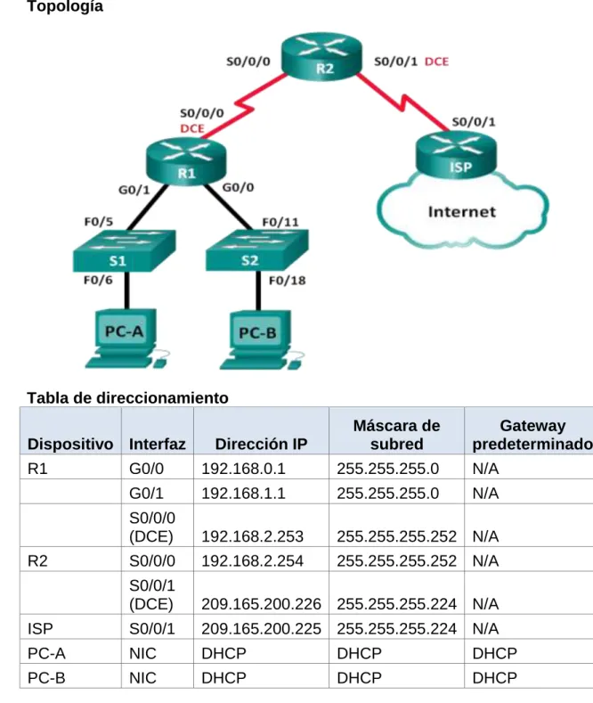
Topología
Tabla de direccionamiento
Dispositivo Interfaz Dirección IP
Máscara de subred
Gateway predeterminado
R1 G0/0 192.168.0.1 255.255.255.0 N/A
G0/1 192.168.1.1 255.255.255.0 N/A
S0/0/0
(DCE) 192.168.2.253 255.255.255.252 N/A
R2 S0/0/0 192.168.2.254 255.255.255.252 N/A
S0/0/1
(DCE) 209.165.200.226 255.255.255.224 N/A
ISP S0/0/1 209.165.200.225 255.255.255.224 N/A
PC-A NIC DHCP DHCP DHCP
PC-B NIC DHCP DHCP DHCP
Objetivos
Parte 1: armar la red y configurar los parámetros básicos de los dispositivos
Información básica/situación
El protocolo de configuración dinámica de host (DHCP) es un protocolo de red que permite a los administradores de red administrar y automatizar la asignación de direcciones IP. Sin DHCP, el administrador debe asignar y configurar manualmente las direcciones IP, los servidores DNS preferidos y los gateways predeterminados. A medida que aumenta el tamaño de la red, esto se convierte en un problema administrativo cuando los dispositivos se trasladan de una red interna a otra.
En esta situación, la empresa creció en tamaño, y los administradores de red ya no pueden asignar direcciones IP a los dispositivos de forma manual. Su tarea es configurar el router R2 para asignar direcciones IPv4 en dos subredes diferentes conectadas al router R1.
Nota: en esta práctica de laboratorio, se proporciona la ayuda mínima relativa a los comandos que efectivamente se necesitan para configurar DHCP. Sin embargo, los comandos requeridos se proporcionan en el apéndice A. Ponga a prueba su conocimiento e intente configurar los dispositivos sin consultar el apéndice.
Nota: los routers que se utilizan en las prácticas de laboratorio de CCNA son routers de servicios integrados (ISR) Cisco 1941 con IOS de Cisco versión 15.2(4)M3 (imagen universalk9). Los switches que se utilizan son Cisco Catalyst 2960s con IOS de Cisco versión 15.0(2) (imagen de
lanbasek9). Se pueden utilizar otros routers, switches y otras versiones del IOS de Cisco. Según el modelo y la versión de IOS de Cisco, los comandos disponibles y los resultados que se obtienen pueden diferir de los que se muestran en las prácticas de laboratorio. Consulte la tabla Resumen de interfaces del router que se encuentra al final de esta práctica de laboratorio para obtener los identificadores de interfaz correctos.
Nota: asegúrese de que los routers y los switches se hayan borrado y no tengan configuraciones de inicio. Si no está seguro, consulte con el instructor.
Recursos necesarios
3 routers (Cisco 1941 con IOS de Cisco versión 15.2(4)M3, imagen universal o similar)
2 switches (Cisco 2960 con IOS de Cisco versión 15.0(2), imagen lanbasek9 o similar)
2 computadoras (Windows 7, Vista o XP con un programa de emulación de terminal, como Tera Term)
Cables de consola para configurar los dispositivos con IOS de Cisco mediante los puertos de consola
Cables Ethernet y seriales, como se muestra en la topología
Parte 1: armar la red y configurar los parámetros básicos de los dispositivos
direcciones IP. Además, configurará los parámetros de IP de las computadoras en la topología.
Paso 1: realizar el cableado de red tal como se muestra en la topología.
Paso 2: inicializar y volver a cargar los routers y los switches.
Paso 3: configurar los parámetros básicos para cada router.
a. Desactive la búsqueda DNS.
b. Configure el nombre del dispositivo como se muestra en la topología.
c. Asigne class como la contraseña cifrada del modo EXEC privilegiado.
d. Asigne cisco como la contraseña de consola y la contraseña de vty.
e. Configure logging synchronous para evitar que los mensajes de consola interrumpan la entrada de comandos.
f. Configure las direcciones IP para todas las interfaces de los routers de acuerdo con la tabla de direccionamiento.
g. Configure la interfaz DCE serial en el R1 y el R2 con una frecuencia de reloj de 128000.
h. Configure EIGRP for R1. R1(config)# router eigrp 1
R1(config-router)# network 192.168.0.0 0.0.0.255 R1(config-router)# network 192.168.1.0 0.0.0.255 R1(config-router)# network 192.168.2.252 0.0.0.3 R1(config-router)# no auto-summary
i. Configure EIGRP y una ruta predeterminada al ISP en el R2. R2(config)# router eigrp 1
R2(config-router)# network 192.168.2.252 0.0.0.3 R2(config-router)# redistribute static
R2(config-router)# exit
R2(config)# ip route 0.0.0.0 0.0.0.0 209.165.200.225
j. Configure una ruta estática resumida en el ISP para llegar a las redes en los routers R1 y R2.
ISP(config)# ip route 192.168.0.0 255.255.252.0 209.165.200.226
k. Copie la configuración en ejecución en la configuración de inicio
Paso 4: verificar la conectividad de red entre los routers.
Parte 2: configurar un servidor de DHCPv4 y un agente de retransmisión DHCP
Para asignar automáticamente la información de dirección en la red, configure el R2 como servidor de DHCPv4 y el R1 como agente de retransmisión DHCP.
Paso 1: configurar los parámetros del servidor de DHCPv4 en el router R2.
En el R2, configure un conjunto de direcciones DHCP para cada LAN del R1. Utilice el nombre de conjunto R1G0 para G0/0 LAN y R1G1 para G0/1 LAN. Asimismo, configure las direcciones que se excluirán de los conjuntos de direcciones. La práctica recomendada indica que primero se deben configurar las direcciones excluidas, a fin de garantizar que no se arrienden accidentalmente a otros dispositivos.
Excluya las primeras nueve direcciones en cada LAN del R1; empiece por .1. El resto de las direcciones deben estar disponibles en el conjunto de direcciones DHCP. Asegúrese de que cada conjunto de direcciones DHCP incluya un gateway predeterminado, el dominio ccna-lab.com, un servidor DNS (209.165.200.225) y un tiempo de arrendamiento de dos días.
En las líneas a continuación, escriba los comandos necesarios para
configurar los servicios DHCP en el router R2, incluso las direcciones DHCP excluidas y los conjuntos de direcciones DHCP.
Nota: los comandos requeridos para la parte 2 se proporcionan en el
En la PC-A o la PC-B, abra un símbolo del sistema e introduzca el comando ipconfig /all. ¿Alguno de los equipos host recibió una dirección IP del servidor de DHCP? ¿Por qué?
No ha recibido la dirección ip dhcp en R2, hasta que sea configurado agente de ley
Paso 2: configurar el R1 como agente de retransmisión DHCP.
Configure las direcciones IP de ayuda en el R1 para que reenvíen todas las solicitudes de DHCP al servidor de DHCP en el R2.
En las líneas a continuación, escriba los comandos necesarios para
Paso 3: registrar la configuración IP para la PC-A y la PC-B.
En la PC-A y la PC-B, emita el comando ipconfig /all para verificar que las computadoras recibieron la información de la dirección IP del servidor de DHCP en el R2. Registre la dirección IP y la dirección MAC de cada computadora.
Según el pool de DHCP que se configuró en el R2, ¿cuáles son las primeras direcciones IP disponibles que la PC-A y la PC-B pueden arrendar?
En PC-A 192.168.1.10, En PC-B 192.168.0.10
Paso 4: verificar los servicios DHCP y los arrendamientos de direcciones en el R2.
a. En el R2, introduzca el comando show ip dhcp binding para ver los arrendamientos de direcciones DHCP.
Junto con las direcciones IP que se arrendaron, ¿qué otra información útil de identificación de cliente aparece en el resultado?
b. En el R2, introduzca el comando show ip dhcp server statistics para ver la actividad de mensajes y las estadísticas del pool de DHCP.
¿Cuántos tipos de mensajes DHCP se indican en el resultado?
10
c. En el R2, introduzca el comando show ip dhcp pool para ver la configuración del pool de DHCP.
En el resultado del comando show ip dhcp pool, ¿a qué hace referencia el índice actual (Current index)?
La dirección ip disponible para ser arrendada
d. Introduzca el comando show run | section dhcp para ver la configuración DHCP en la configuración en ejecución.
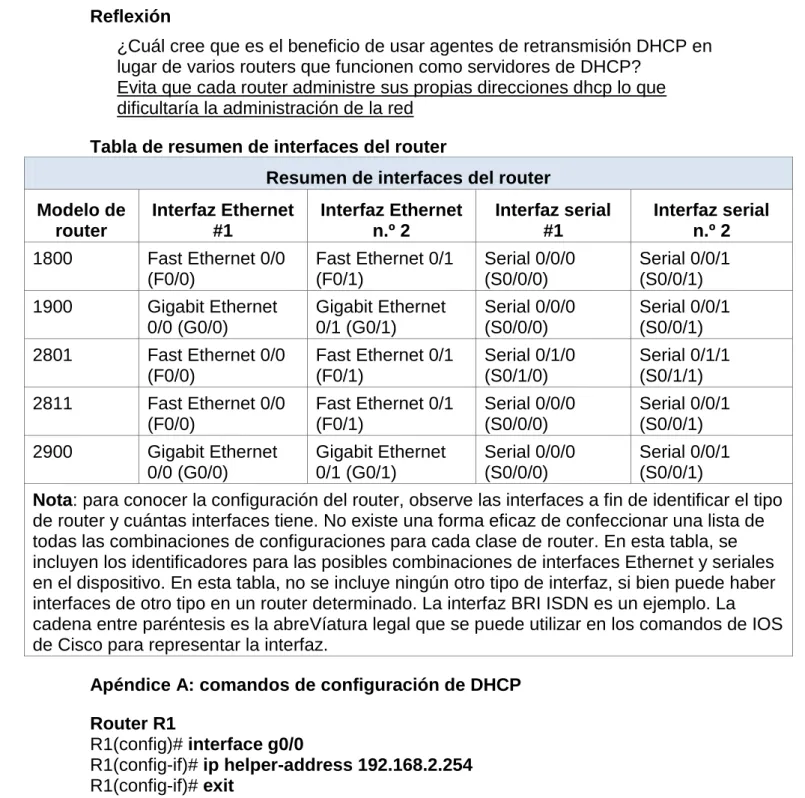
Reflexión
¿Cuál cree que es el beneficio de usar agentes de retransmisión DHCP en lugar de varios routers que funcionen como servidores de DHCP?
Evita que cada router administre sus propias direcciones dhcp lo que dificultaría la administración de la red
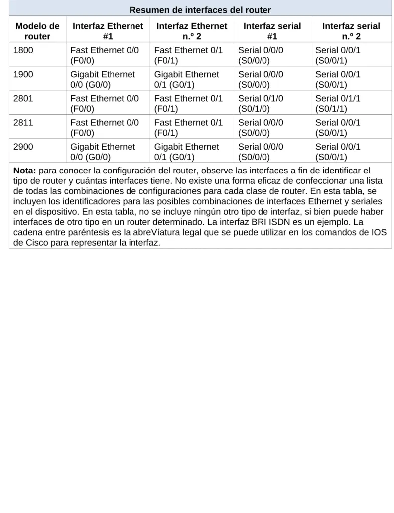
Tabla de resumen de interfaces del router
Resumen de interfaces del router
Modelo de router Interfaz Ethernet #1 Interfaz Ethernet n.º 2 Interfaz serial #1 Interfaz serial n.º 2
1800 Fast Ethernet 0/0
(F0/0)
Fast Ethernet 0/1 (F0/1)
Serial 0/0/0 (S0/0/0)
Serial 0/0/1 (S0/0/1)
1900 Gigabit Ethernet
0/0 (G0/0) Gigabit Ethernet 0/1 (G0/1) Serial 0/0/0 (S0/0/0) Serial 0/0/1 (S0/0/1)
2801 Fast Ethernet 0/0
(F0/0)
Fast Ethernet 0/1 (F0/1)
Serial 0/1/0 (S0/1/0)
Serial 0/1/1 (S0/1/1)
2811 Fast Ethernet 0/0
(F0/0)
Fast Ethernet 0/1 (F0/1)
Serial 0/0/0 (S0/0/0)
Serial 0/0/1 (S0/0/1)
2900 Gigabit Ethernet
0/0 (G0/0) Gigabit Ethernet 0/1 (G0/1) Serial 0/0/0 (S0/0/0) Serial 0/0/1 (S0/0/1)
Nota: para conocer la configuración del router, observe las interfaces a fin de identificar el tipo de router y cuántas interfaces tiene. No existe una forma eficaz de confeccionar una lista de todas las combinaciones de configuraciones para cada clase de router. En esta tabla, se incluyen los identificadores para las posibles combinaciones de interfaces Ethernet y seriales en el dispositivo. En esta tabla, no se incluye ningún otro tipo de interfaz, si bien puede haber interfaces de otro tipo en un router determinado. La interfaz BRI ISDN es un ejemplo. La cadena entre paréntesis es la abreVíatura legal que se puede utilizar en los comandos de IOS de Cisco para representar la interfaz.
Apéndice A: comandos de configuración de DHCP
Router R1
R1(config)# interface g0/0
R1(config-if)# ip helper-address 192.168.2.254 R1(config-if)# exit
R1(config-if)# interface g0/1
R1(config-if)# ip helper-address 192.168.2.254
Router R2
R2(config)# ip dhcp excluded-address 192.168.0.1 192.168.0.9 R2(config)# ip dhcp excluded-address 192.168.1.1 192.168.1.9 R2(config)# ip dhcp pool R1G1
R2(dhcp-config)# network 192.168.1.0 255.255.255.0 R2(dhcp-config)# default-router 192.168.1.1
R2(dhcp-config)# exit
R2(config)# ip dhcp pool R1G0
R2(dhcp-config)# network 192.168.0.0 255.255.255.0 R2(dhcp-config)# default-router 192.168.0.1
R2(dhcp-config)# dns-server 209.165.200.225 R2(dhcp-config)# domain-name ccna-lab.com R2(dhcp-config)# lease 2
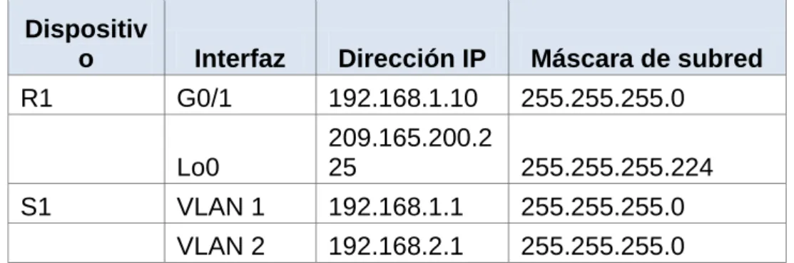
Ejercicio10.1.2.5
Práctica de laboratorio: configuración de DHCPv4 básico en un switch
Tabla de direccionamiento
Dispositiv
o Interfaz Dirección IP Máscara de subred
R1 G0/1 192.168.1.10 255.255.255.0
Lo0
209.165.200.2
25 255.255.255.224
S1 VLAN 1 192.168.1.1 255.255.255.0
VLAN 2 192.168.2.1 255.255.255.0
Objetivos
Parte 1: armar la red y configurar los parámetros básicos de los dispositivos
Parte 2: cambiar la preferencia de SDM
Establecer la preferencia de SDM en lanbase-routing en el S1.
Parte 3: configurar DHCPv4
Configurar DHCPv4 para la VLAN 1. Verificar la conectividad y DHCPv4.
Parte 4: configurar DHCP para varias VLAN Asignar puertos a la VLAN 2.
Configurar DHCPv4 para la VLAN 2. Verificar la conectividad y DHCPv4.
Parte 5: habilitar el routing IP Habilite el routing IP en el switch. Crear rutas estáticas.
Información básica/situación
Un switch Cisco 2960 puede funcionar como un servidor de DHCPv4. El servidor de DHCPv4 de Cisco asigna y administra direcciones IPv4 de conjuntos de direcciones identificados que están asociados a VLAN específicas e interfaces virtuales de switch (SVI). El switch Cisco 2960 también puede funcionar como un dispositivo de capa 3 y hacer routing entre VLAN y una cantidad limitada de rutas estáticas. En esta práctica de laboratorio, configurará DHCPv4 para VLAN únicas y múltiples en un switch Cisco 2960, habilitará el routing en el switch para permitir la comunicación entre las VLAN y agregará rutas estáticas para permitir la comunicación entre todos los hosts.
Nota: en esta práctica de laboratorio, se proporciona la ayuda mínima relativa a los comandos que efectivamente se necesitan para configurar DHCP. Sin embargo, los comandos requeridos se proporcionan en el apéndice A. Ponga a prueba su conocimiento e intente configurar los dispositivos sin consultar el apéndice.
versión 15.2 (4) M3 (imagen universalk9). Los switches que se utilizan son Cisco Catalyst 2960s con IOS de Cisco versión 15.0 (2) (imagen de
lanbasek9). Se pueden utilizar otros routers, switches y otras versiones del IOS de Cisco. Según el modelo y la versión de IOS de Cisco, los comandos disponibles y los resultados que se obtienen pueden diferir de los que se muestran en las prácticas de laboratorio. Consulte la tabla Resumen de interfaces del router que se encuentra al final de esta práctica de laboratorio para obtener los identificadores de interfaz correctos.
Nota: asegúrese de que el router y los switches se hayan borrado y no tengan configuraciones de inicio. Si no está seguro, consulte con el instructor.
Recursos necesarios
1 router (Cisco 1941 con IOS de Cisco versión 15.2 (4) M3, imagen universal o similar)
2 switches (Cisco 2960 con IOS de Cisco versión 15.0 (2), imagen lanbasek9 o similar)
2 computadoras (Windows 7, Vista o XP con un programa de emulación de terminal, como Tera Term)
Cables de consola para configurar los dispositivos con IOS de Cisco mediante los puertos de consola
Cables Ethernet, como se muestra en la topología
Armar la red y configurar los parámetros básicos de los dispositivos
Realizar el cableado de red tal como se muestra en la topología.
Inicializar y volver a cargar los routers y switches.
Configurar los parámetros básicos en los dispositivos.
Desactive la búsqueda del DNS.
Asigne class como la contraseña de enable y asigne cisco como la contraseña de consola y la contraseña de vty.
Configure las direcciones IP en las interfaces G0/1 y Lo0 del R1, según la tabla de direccionamiento.
Configure las direcciones IP en las interfaces VLAN 1 y VLAN 2 del S1, según la tabla de direccionamiento.
Cambiar la preferencia de SDM
Switch Database Manager (SDM) de Cisco proporciona varias plantillas para el switch Cisco 2960. Las plantillas pueden habilitarse para admitir funciones específicas según el modo en que se utilice el switch en la red. En esta práctica de laboratorio, la plantilla lanbase-routing está habilitada para permitir que el switch realice el routing entre VLAN y admita el routing estático.
Mostrar la preferencia de SDM en el S1.
En el S1, emita el comando show sdm prefer en modo EXEC privilegiado. Si no se cambió la plantilla predeterminada de fábrica, debería seguir siendo default. La plantilla default no admite routing estático. Si se habilitó el direccionamiento IPv6, la plantilla será dual-ipv4-and-ipv6 default.
S1# show sdm prefer
The current template is "default" template.
The selected template optimizes the resources in The switch to support this level of features for 0 routed interfaces and 255 VLANs.
¿Cuál es la plantilla actual?
Default, default dual-ipv4-and-ipv6, lanbase-routing
Cambiar la preferencia de SDM en el S1.
Establezca la preferencia de SDM en lanbase-routing. (Si lanbase-routing es la plantilla actual, continúe con la parte 3). En el modo de
configuración global, emita el comando sdm prefer lanbase-routing. S1 (config)# sdm prefer lanbase-routing
Changes to the running SDM preferences have been stored, but cannot take effect
Until the next reload.
Use 'show sdm prefer' to see what SDM preference is currently active.
¿Qué plantilla estará disponible después de la recarga? lanbase-routing
Se debe volver a cargar el switch para que la plantilla esté habilitada. S1# reload
System configuration has been modified. Save? [yes/no]: no Proceed with reload? [confirm]
Nota: la nueva plantilla se utilizará después del reinicio, incluso si no se guardó la configuración en ejecución. Para guardar la configuración en ejecución, responda yes (sí) para guardar la configuración modificada del sistema.
Verificar que la plantilla lanbase-routing esté cargada.
Emita el comando show sdm prefer para verificar si la plantilla lanbase-routing se cargó en el S1.
S1# show sdm prefer
The current template is "lanbase-routing" template. The selected template optimizes the resources in The switch to support this level of features for 0 routed interfaces and 255 VLANs.
Number of unicast mac addresses: 4K
Number of IPv4 IGMP groups + multicast routes: 0.25K Number of IPv4 unicast routes: 0.75K
Number of directly-connected IPv4 hosts: 0.75K Number of indirect IPv4 routes: 16
Number of IPv6 multicast groups: 0.375k Number of directly-connected IPv6 addresses: 0.75K Number of indirect IPv6 unicast routes: 16