Instituto Tecnológico y de Estudios Superiores de Monterrey
Campus Monterrey
School of Engineering and Sciences
New Generation of 3D printed electrospray sources for microencapsulation in biomedical applications
A thesis presented by
Benjamín Evani Bejarano de Jesús
Submitted to the
School of Engineering and Sciences
in partial fulfillment of the requirements for the degree of Master of Science
In
Manufacturing Systems
Instituto Tecnológico y de Estudios Superiores de Monterrey
Campus Monterrey
School of Engineering and Sciences
The committee members, hereby, certify that have read the thesis presented by Benjamín Evani Bejarano de Jesús and that it is fully adequate in scope and quality as a partial requirement for the degree of Master of Science in Manufacturing Systems
_______________________ Dr. Daniel Olvera Trejo
Tecnológico de Monterrey School of Engineering and Sciences Principal Advisor
_______________________ Dr. Alex Elías Zúñiga
Tecnológico de Monterrey School of Engineering and Sciences Committee Member or Co-advisor
________________________ Dr. Oscar Martinez Romero
Tecnológico de Monterrey School of Engineering and Sciences Committee Member
________________________ Dr. Erika García López
Tecnológico de Monterrey School of Engineering and Sciences Committee Member
_______________________ Dr. Ruben Morales Menendez Associate Dean of Graduate Studies School of Engineering and Sciences
Dedication
To my parents, brothers, and sister,
who always believed in my crazy ideas and decisions,
Acknowledgements
I would like to express my deepest gratitude to all those who have been helping me during the development of the work.
I want to thank Dr. Daniel Olvera who was the advisor for my thesis development for his guidance and motivation, also Dr. Alex Elías and Dr. Erika García whose support was extremely valuable for this project.
And also I want to thank Dr. Oscar Martínez and Dr. Alex Elias whose are members of the committee and it was also important their support for the acquisition of the material and equipment for the development of this project.
I do not forget the Tecnológico de Monterrey support on tuition and CONACyT with the support for living expenses.
New Generation of 3D printed electrospray sources for microencapsulation in biomedical applications
by
Benjamín Evani Bejarano de Jesús
Abstract
Additive manufacturing by Digital Light Processor stereolithography (DLP-SLA) has shown a great potential to create high-density microfluidic devices due to it offers high resolution and relatively low-cost. In this work, the fabrication of 3D printed coaxial electrospray sources with a high density of emitters are reported by using DLP-SLA technology. The 3D printed electrospray sources have also proven to work correctly as a source of microencapsulation. To accomplish the objectives of the study, it was addressed in three sections primarily. First, the influence of the involved parameters on the final properties of printed microchannels was evaluated by the analysis and characterization of this promising additive manufacturing technology. Second, based on its maximum printing capabilities, multiplexed electrospray sources were designed. To manufacture suitable channels with diameters up to 160 µm, it was key to establish the smallest dimensions of the new devices, which were successfully printed with 41 and 57 coaxial emitters respectively. Finally, Vitamin D and alginate hydrogel were used to produce core-shell microparticles as an initial exploration in the encapsulation of biomedical substances via coaxial electrospraying. The accurate encapsulation was dependent on the flow rate, applied voltages, and mainly on the concentration of alginate solution.
List of Figures
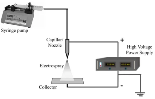
Figure 1. A simple schematic diagram of the experimental setup for electrospray. ... 19
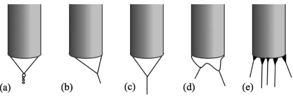
Figure 2. Spraying modes: (a) dripping, (b) spindle, (c) single cone-jey, (d) ramified (e) multi-jet. ... 20
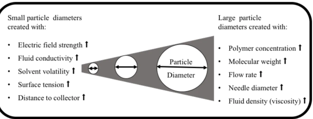
Figure 3. Schematic diagram of the influence of electrospraying parameters on the size of particles (⬆: increase). [24] ... 26
Figure 4. Schematic of DLP-SLA equipment. ... 30
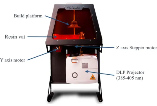
Figure 5. 3D printer B9Creator® V1.2, main components. ... 33
Figure 6. Resin preparation to be used in DLP-SLA printer. ... 34
Figure 7. 1) Layout on the virtual platform, 2) Part Slicing, 3) Setting exposure times ... 35
Figure 8. DLP-SLA Printing process, bottom-up manufacturing layer by layer. ... 36
Figure 9. Post processing ... 37
Figure 10. Specimens Type V, ASTM D638, printed in the horizontal direction. ... 38
Figure 11. CAD template to determine accuracy and shrinkage test. A) Plate with bars, varying the width. B) Plate with tubes and square columns with different sizes. The measures description is shown in Appendix. ... 39
Figure 12. CAD of chessboard sample (1cm2) ... 40
Figure 13. CAD sketches, a cube with an array of helical channels, a) exterior, and b) interior view. Pyramid with an array of linear channels, c) exterior, and d) interior view. ... 43
Figure 14. Schematic of the experimental setup used in the generations of microcapsules of alginate-vitamin D via single coaxial electrospray. ... 46
Figure 15. Chart with tensile test results for various groups of samples printed with the three commercials resins available, post-cured at three different times and heat-treated at 90º C for 20 minutes. ... 49
Figure 16. SEM micrographs. Images on the left column show the lateral views of chessboard a) sample printed with Black resin, b) sample printed with Cherry resin, and c) sample printed with Yellow resin. Images on the right column show magnification of their top of the rooks. ... 54
Figure 17. FTIR spectra of printed samples without post-curing and submerged in isopropyl alcohol during 3 different times: a) spectra of Black resin, b) spectra of
Cherry resin, and c) spectra of Yellow resin. ... 56 Figure 18. Comparison of channel outlet diameters varying the layer thickness. Images
from scanning electron microscope show a) and b) channel outlets of samples printed with 30µm layers, c) and d) channels outlets of samples printed with 20µm, e) and f) channel outlets of samples printed with 15µm layers. ... 58 Figure 19. 3D printed planar array of 41 coaxial electrospray emitters in 1 cm2 of active
area with one Mexican peso coin for comparison. ... 60 Figure 20. 3D printed planar array of 57 coaxial electrospray emitters in 1 cm2 of active
area with one Mexican peso coin for comparison. ... 61 Figure 21. Optical image of multiplexed coaxial emitters source filled with two different
colored deionized water. ... 62 Figure 23. a) Non-homogenous deformed droplet b)Taylor cone of a single-coaxial emitter.
... 64 Figure 24. a) Optical microscope image of microcapsules core-shell of vitamin D/alginate,
b) size distribution of core/vitamin D (yellow bars) and shell/alginate (blue bars) diameters. ... 65
List of Tables
Table 1. Dimensions of features of the specimens for channels characterization. ... 43
Table 2. Dimensions of features of the coaxial electrospray devices. ... 44
Table 3. Minimum measurements printed of the critical dimensions in each geometry. ... 51
Table 4. Mean percentage of shrinkage with a layer thickness of 20µm and 30µm. ... 52
Table 5. Mean percentage of shrinkage in inner and outer diameter of vertical tubes. ... 53
Table 6. Diameter and mean shrinkage of the smallest microchannels printed with a build angle to the horizontal plane. ... 57
Contents Chapter 1 Introduction ... 13 Introduction ... 13 Motivation ... 15 Problem Statement ... 16 Thesis Hypothesis ... 16 General Objective ... 17 Specific Objectives ... 17
Chapter 2 Literature Review ... 18
Electrohydrodynamic atomization ... 18
Encapsulation Technology ... 21
Microencapsulation by using coaxial electrospray technology ... 23
Vitamin D and the importance of its supply in México ... 26
Additive Manufacturing ... 27
Digital Light Processing Stereolithography ... 29
Chapter 3 Materials and Methods ... 32
Methodology of the printing process and its characterization ... 32
Materials ... 32
Equipment ... 33
Description of the DLP-Stereolithography printing process ... 34
Resin preparation ... 34
Layout and printing settings ... 35
Printing process ... 35
Post processing... 36
Mechanical Properties ... 37
Accuracy and shrinkage ... 38
Evaluation of resins resolution ... 39
Chemical compatibility ... 40
Chapter 4 Identification of process parameters and methodology ... 41
Multiplexed coaxial electrospray devices with a density of 41 and 57 emitters in an
active area equal to 1cm2 ... 44
Encapsulation of Vitamin D via Single coaxial electrospray ... 45
Single coaxial electrospray ... 45
Chapter 5 Results and discussion ... 48
Mechanical properties ... 48
Accuracy and shrinkage ... 50
Resins resolution ... 53
Chemical compatibility ... 55
Effect of exposure to isopropyl alcohol ... 55
Chapter 6 Identification of process parameters and methodology ... 57
Statistical analysis ... 57
Multiplexed coaxial electrospray devices with a density of 41 and 57 emitters in an active area equal to 1cm2 ... 59
Encapsulation of Vitamin D via single coaxial electrospray ... 62
Conclusions ... 66
Chapter 1 Introduction
Introduction
Micro and nano-encapsulation is a new technology that has wide applications in food industries, agrochemical, cosmetic and pharmaceutical industries. Encapsulation can be defined as the process of enclosing substances with an inert material that protects the content from the environment as well as control drug release. The production and control of capsules of micrometer or even nanometer size with a narrow size distribution are interest in industrial and scientific applications. It may be motivated by a broad spectrum of reasons: to deliver a given substance to a particular receptor, to isolate an unstable component from an aggressive environment, to prevent decomposition of a sensitive compound under a certain atmosphere, to control dosage, to mask tastes and so forth [1].
A wide range of core materials may be either solid or liquid, like live cells, adhesives, dyes, flavors, hormones, nutrients, vitamins, enzymes, agrochemical, pharmaceuticals etc., can be encapsulated, and the encapsulating agent is usually a polymer. The key issue is the way to form the micrometer or nanometer size capsules from bulk components, with controllable and adjustable coating thickness [2].
One of the most widely used methods to obtain micro and nanometer capsules is based on emulsion technology. Here two immiscible fluids, one carrying the substance to be encapsulated and the other one carrying the polymer for the shell follow consecutive steps of mixing the immiscible phases at a high speed, solidifying the drug-loaded particles
and extracting the particles from the liquid phase. A double emulsification process produces drug-loaded following a four steps procedure.
Emulsion technology possess a number of unique characteristics that render them suitable for drug delivery. However, their complex nature does not always make them a viable option as encapsulation technology, furthermore, emulsions processes generally take several hours to carry out. [3].
Coaxial electrospray is an electrohydrodynamic atomization process (EHDA) that produces multilayer microparticles and nanoparticles by introducing coaxial electrified jets. In compared to other micro/nanoencapsulation processes, coaxial electrospray has several potential advantages such as high encapsulation efficiency, effective protection of bioactivity and uniform size distribution. In electrospray (ES) technique, a conducting liquid is gradually injected through a capillary tube. A high-voltage, from 2kV up to 10kV, is applied between the capillary tube and the tip of the tube, resulting in an electrical field. When the electric potential between the liquid and electrode rises to a few kilovolts, the meniscus at the tip exit develops a conical shape, commonly called Taylor cone. The induced electrical tension at the meniscus surface pushes it away from the tip of the Taylor cone, contrasting the surface tension, resulting in a spray of highly charged droplets [4].The most common electrospray sources are a small capillary or nozzle made from a variety of materials such as metals, silicon, glass, plastic or even paper [5].
decreasing costs, and fast-improving resolution and throughput. AM holds the promise of nearly unlimited design and creation flexibility using either metal or soft-materials. In recent years, faster and cheaper AM technologies have been developed which can produce high print qualities. Recently, there has been a great interest in the design and investigation, of multiplexed electrohydrodynamic systems manufactured for production of particles [6] and fibers [7]. Indeed, digital light processing (DLP), has been one of the photopolymerization methods applied to manufactured these fluidic devices owing to high accuracy (with a resolution of some tens of microns) and availability of relatively low-cost machines [8]. Since electrospray sources are fundamental parts of a electrohydrodynamic process, in the present work, we stake the use of DLP for the development and improvement of coaxial electrospray emitters.
Motivation
From all solid freeform fabrication technologies, which are included: fused deposition modeling (FDM), (selective) laser sintering (SLS or LS) and stereolithography by digital light processing (DLP). DLP Stereolithography is superior to all other technologies, in terms of accuracy and resolution, it has the feasibility to manufacture complex geometries at the microscale, for example, a study showed the fabrication of flow channels with a cross section as 60µm x 108µm [35]. Another example that exemplifies the capabilities of DLP stereolithography, just two years ago, it was reported the first MEMS (micro-electromechanical systems) multiplexed coaxial electrospray source. It is a microfluidic device which has internal channels, and the smallest sections of the channels have a diameter of 450 µm. Working as electrospray, it showed uniform array operation, which
validates a promising microencapsulation technology compatible with low cost and large-market applications [6].
Problem Statement
To offer and sustain the use of 3D printed devices with high density of emitters, such as an effective coaxial electrospray source of low cost that aims to overcome the disadvantages of others analog technologies. For example, most of the existing technologies based on these electrohydrodynamic atomization technologies for core-shell particle production have serious constraints. The more representative drawback is the low production rate to produce micro/nanocapsules, this issue lowers the throughput substantially. Thus, to overcome this constraint, it can be addressed by multiplexing the spray sources, i.e. by increasing the number of emitters per unit area the flow rate performance also will be increased [9].
Thesis Hypothesis
DLP-Stereolithography is a promising 3D printing technology with high resolution for microfabrication, this is the reason the 3D printer which will be used in this work is based on this type of technology. Thus, starting from that downsizing microchannels is what the study will be focusing on. To characterize the technology, based on the study of its parameters and the characteristics of the resins, will allow us to establish a methodology that can be extrapolated to any printer that works with the same basis.
General Objective
Starting from the characteristics of the MEMS multiplexed coaxial electrospray device that has been already mentioned [7], which has 25 emitters in an area of 1 cm2. The general objective is to increase the density of emitters for the same working area (1 cm2). The key to achieving the goal is by shrinking the diameter of the emitters, in this way, the layout of the emitters can be increased. The maximum possible arrangement of emitters will depend on the minimum diameter of channel that can be printed in the DLP-Stereolithography printer. These dimensions are used to design the smallest structures present in the device. As a result of the increase in the number of emitters per unit area, the throughput production of core-shell microparticles also is enhanced.
Specific Objectives
• Develop a statistical estimation method of the DLP-SLA process to determine the smallest possible channels diameters. Where the output of the model is fully determined by the parameter values and the initial conditions.
• Evaluate the post-processing parameters (assessing the physical and chemical degradation because of the isopropyl alcohol exposition and also evaluating the effect of UV-light post-curing time in mechanical properties) in order to obtain the suitable physical and chemical properties of the printed material
• Design specimens within 3D computer-aided design (CAD) for the applicable characterization
• Asses the parameters to encapsulate vitamin D in alginate, by coaxial electrospray process, and evaluate the distribution of microcapsules sizes.
Chapter 2 Literature Review
Electrohydrodynamic atomization
Electrohydrodynamic atomization technique (EHDA), meaning the atomization of a moving (dynamic) liquid (hydro) in an electric (electro) field, technique which is also known as electrospray, has been studied for more than one century. The history of EHDA goes back to 1915 when Zaleny published the first photograph of electrostatic atomization, he showed the conical shape of droplets in the electric field, and also the generation of a mist of water in the cone tip. In 1952, a study performed by Vonnegut and Neubauer showed theoretical and experimental studies about the monodispersity of droplets from electrostatic spray [10]. Taylor, in 1964, was the first to demonstrate that electrostatic pressure and capillary pressure can be balanced at any point on the surface of a liquid cone [11]. Nonetheless, since 1990s it has begun to be used for producing and processing micro and nanostructured materials and researchers have been following this trend of study up to present day. A simple electrospray setup is shown in Figure 1.
This process is characterized by a low liquid flow that under the proper conditions can be atomize into relatively small droplets. The electrospray process uses an electric field as the source of energy to generate a spray. In EHDA process, applying a high voltage to a liquid droplet that forms at the tip of a nozzle leads to the creation of electrostatic force inside it, called coulomb force. This electric field causes acceleration of the charged liquid towards the tip of the nozzle. Depending on the strength of the electric field and the physical properties of the liquids, these interactions result in the formation of different
conical sprays at the tip of the nozzle and lastly generation of continuous production of fine droplets [12].
Figure 1. A simple schematic diagram of the experimental setup for electrospray.
When the electric force overcomes the surface tension force at the surface of a droplet, due to the charge on the droplets, a maximum surface charge density, called Rayleigh limit, is induced on the droplets. This maximum surface charge causes Coulomb fission of the liquid droplets into smaller droplets. This activity happens at the Taylor Cone, referring to the progressive shrinkage of unstable, charged microdroplet into the cone from which the charged droplets will be ejected as soon as the surface tension is overcome by the Coulomb force [13].
Figure 2. Spraying modes: (a) dripping, (b) spindle, (c) single cone-jey, (d) ramified (e) multi-jet.
Various spraying modes can take place during electrospraying (Figure 2), the EHDA mode will most importantly determine by a range of parameter the physical properties of the liquid and system parameters. This mode will change depending on the magnitude of the applied electric field. At lower voltages, there is an intermittent jet formation generates the “dripping”, “spindle”, “multispindle”, and “ramified-meniscus” modes. By increasing the voltage, a “single/stable cone-jet”, “oscillating-jet”, or “multi-jet” can be observed. The most desired is the stable cone-jet mode, because of its stability and reproducibility for the production of fine particles [14].
Several electrospray setups have been investigated. The nozzle configuration varies from a simple needle of different diameters to highly technologically advanced multiplexed nozzles, these characteristics provide flexibility to the experimental setup [15].
Additionally, MEMS (micro-electromechanical systems) and microfluidic technologies allow high control on droplet size and simple post-processing on the produced particles. However, most of the present methods based on microfluidic technologies for
capsule production have two serious limitations: one of them is the low production rate generated by only microfluidic device and the other one is the constraint in particle diameter, inasmuch as the majority of these techniques, the smallest drop diameter that may be generated is on the same scale of the thinnest element in the system [16].
Encapsulation Technology
Encapsulation can be defined as a technology of casting solids, liquids, or gaseous materials in micro/nanocapsules. The size of the capsules may range from nanometer to several millimeters in size and can have a multitude of different shapes, depending on the material and methods used to prepare them. The microcapsules can release their content at controlled rates under specific conditions. Encapsulation depends on the physical and chemical properties of the material to be encapsulated. Especially the microencapsulation technology has been employed in a diverse range of industry such as chemicals [20], food [26], and more specifically in the pharmaceutical field [24] [47], where polymeric micro and nanoparticles are capable to being administered as oral, inhalable, injectable, topical, and local/target drug-delivery systems.
One of the first development of encapsulation works was in the 1950s when Green and his coworkers produced microencapsulated dyes by complex coacervation of gelatin and gum Arabic, for the manufacture of carbonless copying paper [17].
Microcapsules provide a means to protect sensitive components by reducing its reactivity to the outside environment, transform liquids into easily handled solid
ingredients, mask taste or odor of active ingredients, improve processing of materials and also this technology can incorporate controlled release attributes into the product formulations, such as time-release, targeted-release, or trigger-release mechanisms.
Several techniques are available to design capsules depending on the end use of the final product. The most common techniques for nanoencapsulation and microencapsulation are emulsification (single and double emulsion), emulsification-solvent evaporation, spray-drying, porous glass membrane, and coacervation [18].
Nonetheless most of the above techniques have several disadvantages, such as low drug-loading efficiency, limitations to scale up, broad size distribution, inhomogeneous size, low ability to fabricate small particles at the nanoscale, lack of reproducibility, difficulties for incorporation of hydrophilic drugs and the use of nondegradable emulsifiers. Likewise, the protein denaturalization, degradation or inactivation of the drug can occur, due to organic solvent exposure, high shear stress and high temperature [3], [19].
For example, emulsification which is the most popular ones, it may not always be a favorable method of encapsulation for ingredients that are insoluble in either hydrophilic or hydrophobic environments. It is also important to mention that in the case of emulsions; active pharmaceutical ingredients must be solubilized in their respective phases. This could prove to be a limiting factor depending on the amount of active pharmaceutical ingredients necessary for delivery.
surfactants that are considered acceptable are only acceptable up to certain concentrations. Finally, emulsions are sensitive to temperature and salinity changes and may undergo phase changes when exposed to higher or lower than normal temperatures or salinity concentrations. [47]
Microencapsulation by using coaxial electrospray technology
The Electrohydrodynamic atomization technique (EHDA) has been widely employed in the encapsulation of therapeutic agents in biodegradable polymeric particles for controlled and sustained drug release applications. It is a powerful and advantageous technique, these potential advantages are: a) it produces droplets with sizes from hundreds of micrometers down to tens of nanometers; b) the size distribution of the droplet size can be nearly monodisperse, the encapsulation efficiency and droplet size can be mainly controlled via flow rate of the liquid and the voltage at the capillary nozzle; c) the drug losses are minimal as compared to conventional particulate formation methods; d) the free charges that converge on the surface of droplet do not affect the biomolecules, the fact that the droplets are electrically charged simplify control of their motion; e) it can be carried out without sophisticated equipment, this has been shown that can be done with 3D printed multiplexed sources. Furthermore, some other advantages which consist in the ease of operation, high loading level, and the technique have the capability to be scaled up easily by employing an array of electrospray atomizers to increase the production rate [18], [20]– [22].
The encapsulation via EHDA can be achieved by several methods: collision of droplets of opposite polarity, electrospraying of a drug dissolved/suspended in polymer solution with solidification by evaporation, electrospraying of a drug dissolved/suspended in polymer with solidification by a chemical or ionic crosslinker, and coaxial electrospraying where a nozzle with two needles of different gauge sizes is arranged coaxially to dispense two different solutions simultaneously, that is why this concentric configuration is used to fabricated monodisperse multilayer particles with size ranging from tens of nanometer to hundreds of micrometer [3].
The coaxial electrospray shown increases the number of centered nozzles to three [49] and is mainly used to fabricate multilayer spheres. In coaxial setups, the most commonly used is coaxial of two capillary nozzles [23]. This electrospray variant holds immense potential as the core-shell structure will reduce any burst release and may achieve a near zero-order release kinetics. Furthermore, it spends less time to fabricate capsules [24], it has the potential to achieve high encapsulation rate (nearly 100%) [3], efficient loading capacity, precise control of the core-shell geometry, and protection of the sensitive therapeutic loads from process-induced denaturalization and aggregation. This process can be scalable for mass production of drug-loaded for microcapsules and nanocapsules [25].
When it concerns producing particles at micro or nanoscale a stable cone-jet mode is desirable, where a very low flow rate is often required. However, most applications require a high throughput, then this causes severe restrictions to the use of an only one electrospray emitter [26]. In order to overcome this drawback, increasing the number of
rate to be dispersed and keeping the homogenous dispersity of the generated droplets [27]. Systems with multiple emitters with different arrangements have been designed to increase the productivity and also to increase the area of atomization for large-scale production, these configurations can be with linear array [28], planar/square array [29], hexagonal pattern [30], circular array [5], etcetera. Multiplexing involves the presence of reservoir from which each emitter is fed. One of the most difficult issue associated with a multiplexed electrospraying is the equal distribution of liquid in all emitters and the adjacent emitter repel each other and as a result the electric field on the tip of each emitter at different positions could be not uniform [31].
Although electrospray is a promising method for the fabrication of particles, there are some limitations to this technique. The main problem is large number of processing parameter and apparatus parameters can make its optimization highly complex. To achieve the appropriate results and desired particles or capsules, it is better to examine the step-wise manner of the process in order to determine the relationship between processing parameters and characteristics of the particles. The parameters include process parameters such as the concentration of polymer, drug, solvent, surfactant, protein, polymer ratio, as well as apparatus parameters, such as flow rate, voltage, needle gauge, and distance to the electrode. These parameters have an interconnected influence on the electrical conductivity, viscosity, surface tension, distribution, particle size, encapsulation efficiency, loading capacity, and in vitro release profiles [15]. The effect of main parameters known to the size of produced particles in an experiment electrospray is summarized in Figure 3.
Figure 3. Schematic diagram of the influence of electrospraying parameters on the size of particles (⬆: increase). [24]
Vitamin D and the importance of its supply in México
The National Institute of Public Health from Mexico (INSP) recently warned about vitamin D deficiency in the Mexican population as a major health problem in the near future. Studies conducted by this institute showed that 30.1% from a total of 9.5 million patients analyzed experienced vitamin D deficiency, of which: 50% of kindergarten children and 25% of elementary school children showed moderate deficiency with a prevalence severe below of 1%. When it comes to adolescents and adults the experienced 31.13% and 33.33% deficiency of this vitamin, respectively [50]. This agrees with that reported by Schnadower et al. [51] who observed that vitamin D deficiency is not limited to infants and children but can also occur in adolescents.
effects on different tissue types and physiological processes [52]. This vitamin is synthesized in the skin and is obtained from the diet, then transported in the blood to the site where it is activated or inactivated by specific enzymes, subsequently its active form to specific receptors in target tissues, to finale give place to an increase in plasma Ca2+ concentration [52]. This regulation of calcium through vitamin D is essential to maintain healthy and strong bones, as well as for proper growth in children [53]. Its deficiency can cause bone malformations, even disabling the motor functioning of the child. It is important to mention that the action of vitamin D is not only related to bone mineral metabolism and phosphocalcic balance, but also to the mechanisms of secretion and effect of insulin, endothelial function, regulation of resin angiotensin-aldosterone system, control of the cell cycle, apoptosis and the immune system, to mention a few [54]. This is why this vitamin deficiency is also related to an increased risk of diabetes, cardiovascular, oncological, infectious and autoimmune diseases. [53]- [54]
The fortification of foods with vitamin D has been a challenge due to its characteristics since it is hydrophobic and highly unstable in the presence of oxygen, light, heat, temperature and humidity. The food industry has developed several methodologies of microencapsulation, which have been inefficient, to reduce the reactivity of the compounds with the environment or preserve the nutritional value [55].
Additive Manufacturing
Polymers are by far the most utilized class of materials for AM, and the range of polymers used in Additive Manufacturing (AM) encompasses thermoplastics, thermosets,
elastomers, hydrogels, functional polymers, polymer blends, composites, and biological systems. Because polymer-based 3D printing allows the easy fabrication of semi-hollow components with high specific strength and lightweight, its use can be extended to industries, such as automotive, space, architecture, food processing, optics, dentistry, drug delivery, and personalized medicine [34].
AM translates computer-aided design (CAD) virtual 3D models into physical objects. By digital slicing of CAD, 3D scan, or tomography data. AM builds objects layer by layer without the need for molds or machining. AM allows more design freedom because of its ability to form complex shapes and unique geometries, with a minimum need for post-processing, built from tailored material with near-zero material waste [32].
AM technologies and methods are increasing steadily in terms of applications and market share, widening in several manufacturing divisions, such as automotive, medical, aerospace and academic, and are expected that this heavy growth will prolong over the next decades. According to Wohlers Report 2016, this industry grew 25.9% (CAGR, Corporate Annual Growth Rate) to $5165 billion in 2015. The industry growth consists of raw material, 3D printers and services worldwide. The Corporate Annual Growth Rate for the previous three years was 33.8% [33].
Digital Light Processing Stereolithography
Digital light processing (DLP) is an accurate additive manufacturing technology suitable for producing microsystems by photopolymerization, such as high density microfluidic devices [6], microvalves, pumps, and multiplexers with an integrated pump [35], soft pneumatic actuators [8] electromechanical structures or conductive complex structures [36], [37].
In DLP 3D printing technology (see Figure 4) a video projector with a digital light processing (DLP) chip which contains thousands of micro mirrors, digital mirror device (DMD), is used to project a two dimensional pixel-pattern of UV light onto a transparent vat, a complete layer of photosensitive resin can be cured at once. Because the whole layer (slice) of the structure is produced in one exposure step, the build time is considerably short, as it only depends on the layer thickness and on the required exposure time and no additional supporting structure is required [34].
The lateral resolution of DLP systems is usually in the range of 10-50 µm depending on the number of pixels/mirrors provided by the digital mirror device and the optics used to project the patterns onto the build platform. The vertical resolution, that is, the smallest possible layer thickness, mainly depends on the light penetration depth into the material and the resulting curing depth [38].
Figure 4. Schematic of DLP-SLA equipment.
In a photocurable resin, the cure depth is determined by the energy of light to which the resin is exposed. This energy can be controlled by adjusting the power of the light source and the exposure time.
A restriction of photopolymer technologies is the quantity range of available resins, which have to be photocurable stable material with partial optical transparency, moreover, light penetration should be enough to ensure good adherence between layers and satisfactory part resolution [39].
In the field of 3D printing technologies with photopolymers, anisotropy is a typical characteristic, usually the anisotropic features are different from the parts which are made
with other technologies. In this sense, some authors have investigated the influence of build direction on parts made by photopolymerization, and also provide a model that allows the prediction of the mechanical behavior depending on the build direction [39], [40].
Once a part is obtained, it requires draining, washing-off excess resin and finally, a post-curing process with ultraviolet light. This last step is often done to improve mechanical properties of the structures. Since the post-curing step is an important process, previous studies have studied the effect of different degrees of cure, which can present different relations between previews mechanical properties [41].
Even though it is possible to manufacture parts at microscale with DLP-SLA, there has been a consistent drawback with this technology, it causes part distortion and dimensional inaccuracy. DLP-SLA products are made of photocurable resin that always experience volumetric shrinkage during the curing process that is caused by resin curing. If the photocurable resin experience larger shrinkage, the dimensional inaccuracy of products may get larder. Part shrinkage take place during the three successive procedures of producing: building, supporter removing, and post-curing [42].
Chapter 3 Materials and Methods
Methodology of the printing process and its characterization
In order to address the problem statement enunciated previously, in this chapter all the reported information is gathered for the development of this work.
Due to this work is based on a disruptive technology, this means it is a new technology that completely changes the way electrospraying usually is done. The common electrospray emitters are made from different materials such as metal, silicon, glass or plastic. In the case of coaxial atomization, the setups basically consist of 2 or more coupled needles or capillares. Consequently, this work started from learning the operation of the manufacturing technology used to the characterization of a functional device.
Materials
Three commercially available photocurable resins from B9Creations® LLC, Rapid City, SD, USA, were used:
• B9R-1-Cherry • B9R-2-Black • B9R-4-Yellow
According to the supplier, the components of these resins and its proportion of the formulas are trade secret. For all experiments, all resins were used without modification. Each resin has individual printing adjustment in terms of vertical build range, i.e., a minimum and maximum slice thickness. The thickness of the layers could be adjusted for
B9R-1-Cherry from 30 to 50 µm, B9R-2-Black from 30 to 200 µm, and B9R-4-Yellow from 20 to 50 µm.
Equipment
A commercial 3D printer (see Figure 5), B9Creator® (V1.2, B9Creations, LLC, Rapid City, SD, USA), was used in this study. The B9Creator printer is a bottom-up DLP printing system where the light source from a projector is plotted on the bottom surface of the resin vat during printing. A building platform has lifting movement above the resin vat by a stepper motor. The printer uses a DLP projector which provides a 385 nm ultraviolet (UV) light. The resolution is 1920 x 1080 and the projection area is 57.6 mm and 32.4 mm. The normal resolution is, therefore, 30 µm, which corresponds to the square area of each pixel.
Description of the DLP-Stereolithography printing process
All devices and samples used for each characterization were designed by using the CAD software SolidWorks 2017. The sketches of these specimens and objects are described briefly in its respective section. The printing process consists mainly of 4 procedures: resin preparation (see Figure 6), layout and printing settings (see Figure 7),
printing process (see
Figure 8), and post-manufacturing process (see Figure 9). These procedures are described below.
Resin preparation
To prepare the resin for each print, 150 ml were put in vacuum process during 30 minutes, since bubbles can interfere in the mask projection. In order to use a homogeneous mixture of the resin, a bath ultrasonication was undertaken for 10 minutes afterward (Figure 6). After several printing cycles and each time a print has failed, it is necessary to filter the resin in order to separate traces or pieces that have been detached from the buil platform.
Figure 6. Resin preparation to be used in DLP-SLA printer.
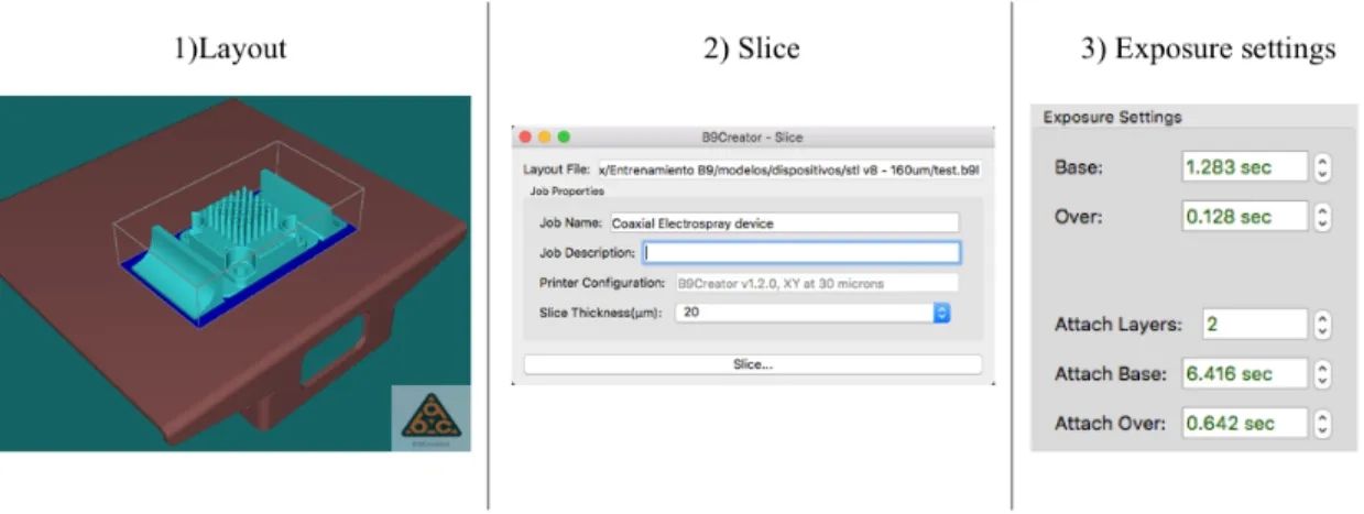
Layout and printing settings
To set the orientation and printing direction, the printer software steps were followed. First, the CAD model of an object is located in the desired position on a virtual building platform. Then the CAD model is sliced and converted into mask images, this 3D printing technique is turned on and the slices are loaded into the control system of the software. The exposure time for each layer is automatically set depending on the chosen layer thickness. The times of exposure are already established in the software settings, and these times vary for each resin. Once the file is generated, the resin is deposited in the vat and the print can be carried out (see Figure 7).
Figure 7. 1) Layout on the virtual platform, 2) Part Slicing, 3) Setting exposure times
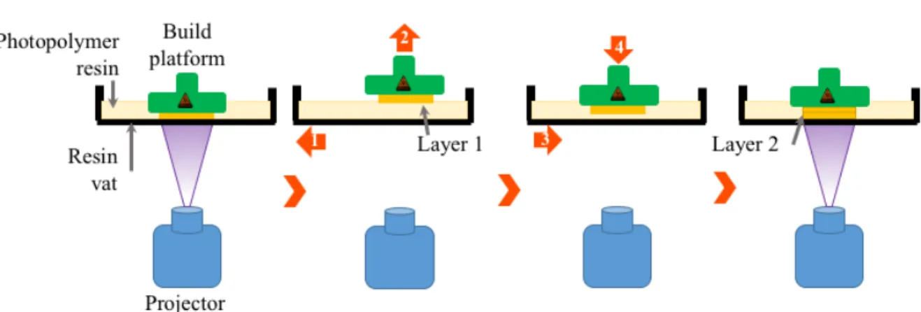
Printing process
The first layer is cured between the bottom of the vat and the surface of the build platform by the projector light projecting a mask image of the desired planar geometry for a preset time. This is time is defined as exposure time.
After each layer is cured, the light source is tuned off and the resin vat shifts along the x-axis (horizontally) to separate the cured layer from the vat bottom. After shearing, the building platform is lifted up by a present distance d to generate a gap between the layer previously printed and the surface of the vat bottom, allowing the new resin to fill into the projection area. The vat then goes back to the projection area, and the build platform goes down, leaving a thickness gap for the new layer. This space is fully filled with resin to cure the next layer. The process is repeated layer by layer until the whole object is fabricated as
shown in
Figure 8.
Figure 8. DLP-SLA Printing process, bottom-up manufacturing layer by layer.
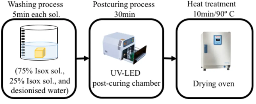
Post processing
After printing, in order to remove the uncured resin on the surface and within the microchannels of the device, the part is carefully removed from the platform to be cleaned by washing off the residual resin with a 3:1 solution of isopropyl alcohol and deionized water for 5 minutes. Then, a second wash is done with a 1:3 solution of isopropyl alcohol and deionized water for 5 minutes. And one last wash for 5 minutes too, but now with deionized water. Finally, it is required a post-curing process, where the part is submerged in
a glass with tap water and this, in turn, in a chamber with UV light exposure for 30 minutes, this time was established from the results of mechanical properties.
Figure 9. Post processing
Mechanical Properties
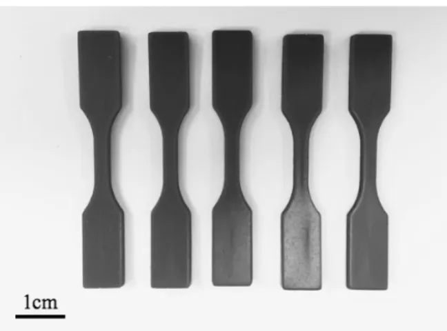
In this experiment, the influence of different UV post-curing process to the change of mechanica properties was considered. Tensile tests of the printed resins specimens were conducted using the INSTRON® 3368 electromechanical testing machine. The speed of test was 1 mm/min. The geometry of specimens for the tensile test used in this study was created accoring to the Standard Method for Tensile Properties of Plastics of America Standard for Testing Materials (ASTM, D638-01). Type V specimens were printed in the horizontal direction, as shown in Figure 10. Groups of at least 5 specimens were tested under the following post-curing process conditions: specimens were post-cured in an UV-led chamber for 5, 15, and 30 minutes, respectively. A heat treatment was undergone for the extra group (90º C for 20 minutes). The control group was not exposed to UV-light either
heat treatment. For all three resins, a comparative of Young’s modulus study was conducted.
Figure 10. Specimens Type V, ASTM D638, printed in the horizontal direction.
Accuracy and shrinkage
In this section, our interest is to determine how the involved parameters affect the volumetric shrinkage since the amount of volumetric shrinkage is the main factor of the dimensional accuracy.
To evaluate the accuracy of three-dimensional DLP prints for each type of resin, panels with 4 geometries of interest were printed with two different layer thickness, 20µm and 30µm. An example of the CAD sketch is shown in Figure 11. The geometries: bars (Figure 11(a)), square columns, circular poles and tubes (Figure 11(b)) were designed in different sizes. A 3D non-contact metrology system (Alicona InfinitFocus, Austria) was used to determine the height and width of the cured geometries, this Alicona microscope is
a 3D micro coordinate measurement machine. A comparative shrinkage percentage was done and the smallest printed parts measure was found.
Figure 11. CAD template to determine accuracy and shrinkage test. A) Plate with bars, varying the width. B) Plate with tubes and square columns with different sizes. The
measures description is shown in Appendix.
Evaluation of resins resolution
Another crucial aspect to study is the comparison of the resolution and surface finish quality between resins. Since the exposure time is the only parameter that can be modified in the printer, a sample with a preliminary layer thickness (20µm) was used for the whole set of resins. The design of the samples was a chessboard of 1 cm2 (with its
pieces: king, queen, rooks, etc.) A qualitative comparison was carried out by analyzing microscopy images. These chessboards were analyzed using electron microscopy (EVO MA25 Zeiss Scanning Electron Microscope, Zeiss, Jena, Germany). The whole set of chessboards were gold sputtered (BIORAD SC-500 Sputter coater) for 3 minutes at 30 mA
before the analysis in the electron microscopy. An image of the CAD file is shown in Figure 12.
Figure 12.CAD of chessboard sample (1cm2)
Chemical compatibility
In order to foresee a possible chemical degradation or deleterious changes in the surface during the cleaning process, this study examines the effect of direct contact with isopropyl alcohol on the structural and chemical resistance. For each resin, a set of printed samples were submerged in isopropyl alcohol (≥99.7%) during different time periods, each sample was submerged during 6, 12, and 24 hours respectively. The control sample was not submerged in isopropyl alcohol. Fourier transform infrared (FT-IR) spectra were obtained using a Perkin Elmer System 2000 FT-IR spectrometer (PerkinElmer Life and Analytical
Sciences, Inc., Wellesley, MA, USA). All spectra were obtained after a background subtraction by averaging 16 scans.
Chapter 4 Identification of process parameters and methodology
It is important to know the parameters involved in the process and the way these parameters affect the outcomes of the printing process. This chapter aims to present a modeling of the DLP-SLA printing process from the analysis of microchannels fabricated semi-perpendicular to the printing direction. The second point that is addressed in the chapter is the description of the multiplexed coaxial devices, which were design based on the minimum printing limits of the B9Creations printer, in terms of smallest wall thickness achieved and also the smallest microchannels printed.
Statistical model
In this section, the DLP process is modeled by using the predefined process parameters. This model will provide the relationship between the process parameters and dimensional errors of the printed channels. For a correct operation as electrospray, the internal architecture of the devices has to be properly built. Hence, special care must be taken with some dimensions and critical geometries. These critical dimensions are the minimum possible thickness printed on vertical walls and the diameter of the channel. Therefore, the devices are design based on these features, which were assessed in the previous sections.
In order to find and analyze the minimum dimensional errors, a set of samples were design replicating the characteristics of the internal channels in the final device, in other words, the design of the pyramid have the same length of microchannels, the diameter reduction as a function of the length and the angle growth. The outlet diameters were also evaluated reducing their dimensions. An additional pair of samples designed with internal channels, but in this case the channels path is linear. The length and growth angle is equivalent to the trajectory that channels actually follow in the helical version. The sketches of the samples are shown and described in Figure 13 and the specifications of the design are listed in Table 1.
Addressing the purpose of the study, samples with a layer thickness of 30µm, 20µm and also one sample with a layer thickness of 15 µm, were printed by DLP-SLA and then characterized with scanning electron microscopy (SEM). For the sample with 15µm of layer thickness an adjustment was made in the exposure settings. Micrographs were taken, in order to have overviews of the build direction side and the detailed edges of the output channels.
Figure 13. CAD sketches, a cube with an array of helical channels, a) exterior, and b) interior view. Pyramid with an array of linear channels, c) exterior, and d) interior view.
Table 1. Dimensions of features of the specimens for channels characterization.
Feature Cube samples
(Helical channels)
Pyramid samples (Linear channels)
Inlet diameter of microchannels [µm] 700, 600, 500 400, 300, 200, 100 Outlet diameter of microchannels [µm] 300, 200,100 600, 400
Height of object [mm] 5.8 2-15
Multiplexed coaxial electrospray devices with a density of 41 and 57 emitters in an active area equal to 1cm2
From the results of resin characterization, it was adjusted a previous device CAD design, with the aim to optimize the emitters density. The multiplexed coaxial device already reported has 25 emitters, whereas two new devices presented in this work have 41 and 57 emitters per square centimeter. The features of each device are described in the next Table 2.
Table 2. Dimensions of features of the coaxial electrospray devices.
Feature 41 emitters 57 emitters
Inlet diameter of helical microchannel
[µm]
450 360
Outlet diameter of helical
microchannel[µm]
200 160
Emitter height [µm] 14.75 13.61
Nozzle height[mm] 7.2 5.96
Average gyration diameter of helical
microchannel [mm]
1.4 1.2
Length of helical microchannel [mm] 19 19
Volume of each internal liquid reservoir [mL]
Encapsulation of Vitamin D via Single coaxial electrospray
This chapter describes the characterization of the devices working as coaxial electrospray sources. It is known the parameters that affect mainly in the droplet generation is the electric field and flow rate, thus, obtaining the conditions for an accurate operating is the first objective, and the microencapsulation of a subtance of interest (vitamin D) with its favorable conditions, is the next step.
Single coaxial electrospray
A 3D printed single-coaxial emitter source was used to produce microcapsules with sodium alginate as the shell and vitamin D diluted in safflower as the core. Alginates capsules are created through the formation of alginate gels in the presence of divalent cations [46]. In the presence of divalent cations such as Ca+, the COO- groups of the
guluronate blocks form physically cross-linked gels. They can trap the cations in a stable, continuous, and thermo-irreversible three-dimensional network.
The schematic setup for coaxial electrospray for the experimental encapsulation is shown in Figure 14. The setup consists of several major components, an aluminum chuck, two syringe pumps from New Era Pumps Systems Inc., Farmingdale, NY, USA. Two syringe of 1mL with an internal diameter of 0.469mm. A high voltage power supply with a dual output, power source from Gamma High Voltage Research Ormond Beach, FL, USA. An extractor electrode and a collector electrode, which are a laser-cut 250 µm-thick 304 stainless steel plate. The extractor has a circular aperture that is concentric to the emitter, both electrodes are integrated to the chuk using screws. The 3D-printed microfluidic device
is also clamped to the chuck using screws. The aluminium chuck is grounded, while the negative bias voltages between 3.5 kV and 6.5 kV are applied to the electrodes. A 6 MP CCD color digital color camera attached to a 12x zoom microscope lens was used to monitor the emitter and the Taylor’s cone stability.
As mentioned in literature review section, in an electrohydrodynamic process several parameters and the properties of the jetting liquids may affect the production of the microcapsules and also the properties of the fabricated capsules. However, in this work, the effect of alginate concentrations and flow rate on the size and size distribution were investigated.
Figure 14. Schematic of the experimental setup used in the generations of microcapsules of alginate-vitamin D via single coaxial electrospray.
In order to assess the reproducibility of electrospraying, 3 replicates of each combination of process parameters were generated. Voltage was turned off between
replicates. After electrospraying each pair of solutions, the resulting jet was collected in a bucket with 3 mL of 6% of calcium chloride. To examine the core-shell structure of the particles, the alginate solution was colored with a blue vegetal dye in order to visualize easily in the microscope.
The size and morphology of the resulting alginate-vitamin capsules were observed by an optical microscope (with a Zeiss SteREO Discovery.V8 microscope.). The average size and standard deviation of the capsules were calculated from the optical microscopy images by analyzing at least 100 capsules using ImageJ software (National Institute of Health, USA).
Chapter 5 Results and discussion
Mechanical properties
It was evaluated the influence of post-curing time, i.e., the effect on the final mechanical properties of the part due to UV light exposure. The influence of thermal treatment was also evaluated. Tensile specimens were printed for mechanical tests. Figure 15 displays tensile test results for various samples of three commercial resins post-cured in a UV-light chamber at 5, 15, and 30 minutes and also heat-treated in a dry oven during 20 minutes at 90º C.
According to the results, it is obviously shown that the UV post-curing process improved the mechanical properties of DLP 3D-printed specimens. Also, it can be noticed that part printed with Yellow resin present the greater mechanical properties than the other specimens. The elastic modulus of Black specimens is slightly higher than Cherry specimens. In the majority of cases, with the thermal process, there was an improvement in the mechanical properties. It means the printed parts were not fully cured even after post-curing in the UV-chamber.
In terms of tensile strength, the specimens printed with Black resin have the highest values, in most of the samples this value is twice as large as the other samples. The Yellow specimens present the lowest tensile strength. Thermal process improved mildly over all the tensile strength. Additionally, there was decreased in the value of elongation at the break after UV post-curing process and after the thermal process as well.
As polymers are likely to experience degradation at elevated temperature [43], which could adversely affect the mechanical properties, it is important to keep the
temperature and duration optimal to minimize the degradation. Thus, for this study the temperature and time for heat treatment were chosen based on photocured and thermal cured resins studies [44][45].
Figure 15. Chart with tensile test results for various groups of samples printed with the three commercials resins available, post-cured at three different times and heat-treated at
Accuracy and shrinkage
Accuracy dependent mainly on the properties of the polymer, part design, part printing method, source light system, and postprocessing method used. In the part printing method, the parameters and also the post-process are an important aspect to assess in this section. In this section the three resins were evaluated with 20µm and 30µm of layer thickness.
Once the samples were subjected to the post-curing process, they were taken to inspection and measured in the Alicona microscope. The critical dimensions of the geometries are listed in Table 3, it includes the dimensions of the smallest printed structures. It is important to know these values because they play an important role in the architecture of the devices. For instance, the thickness of the internal walls depends on the minimum width achieved in the bars.
The only difference found between the printed samples with 20µm and 30µm of layer thickness was in the cylindrical tubes which were clogged. For Yellow resin, it can print unclogged tubes with minimum diameters of 250µm and 300µm by a layer thickness of 20 and 30µm respectively. This happened similarly with black resin, here 20µm of layer thickness allows obtaining a diameter 50µm smaller than printed with layers of 30µm. However, it was noticed that the more times the resin is used, the lower the accuracy. It was found in the cylindrical tubes, where tubes with larger diameters were obtained clogged as prints with the same resin were repeated.
Table 3. Minimum measurements printed of the critical dimensions in each geometry. Geometries Critical dimension (0.5-2.5 mm height) Yellow resin (CAD measurement µm) Cherry resin (CAD measurement µm) Black resin (CAD measurement µm) 20µm* 30µm* 20µm* 30µm* 20µm* 30µm* Bars Width ≥150 ≥150 ≥150 ≥150 ≥250 ≥250 Cylindrical tubes Inner diameter (unclogged) ≥250 ≥300 ≥300 ≥300 ≥400 ≥450 Cylindrical poles Diameter ≥250 ≥250 ≥250 ≥250 ≥300 ≥300 Square columns Lenght ≥200 ≥200 ≥250 ≥250 ≥300 ≥300 * Layer thickness
Parts made of photocurable resin always experience volumetric shrinkage during the curing process that is caused by resin curing unsymmetrically. This has been a consistent problem with photolithography because it causes part distortion and dimensional inaccuracy[42]. In order to explain the influence of the main process parameter on parts, Table 4 shows the analysis of shrinkage varying the layer thickness. The percentage of shrinkage was obtained by computing the difference between the settled sizes in CAD design and the actual sizes measured under the microscope.
To determine the level of significance of some factor in the different process carried out, ANOVA analysis was applied. ANOVA analysis provides information about the significance of one factor on the resulting averages of the variable. A p-value below 0.05
means that the corresponding factor is significant on the variation of a variable with a reliability of 95%. The results show that samples printed with a layer thickness of 20 µm present greater shrinkage in height (Z-axis) than samples printed with 30 µm, that is to say in the build direction of the object. In the opposite case, ANOVA did not show significant differences among the percentage of shrinkage in the horizontal (p-value above 0.05).
Table 4. Mean percentage of shrinkage with a layer thickness of 20µm and 30µm.
Resin
Mean shrinkage (%) with a layer thickness of 20 µm
Mean shrinkage (%) with a layer thickness of 30 µm
X,Y-axis Z-axis X,Y-axis Z-axis
Yellow 3.21 7.06 3.31 5.68*
Cherry 3.07 5.91 3.02 4.4*
Black 2.91 3.69 2.86 3.38
*The result is significant at p<.05
As mentioned, this work focuses primarily on downsizing microchannels below 450µm of diameter. In this way the influence of shrinkage on the structure is assessed. Table 5 compares the influence of the layer thickness and the shrinkage percentage between the outer and inner diameter. ANOVA analysis did not show significant differences in the percentage of shrinkage in both diameters because of the layer thickness. However, noticeable the shrinkage in inner diameters is larger than the outer one. It is corroborated by the statistical analysis using a p-value above 0.05.
This interesting result contributes to reducing the inner diameters of the channels built in the vertical direction (Z-axis) in some cases above of 10% as shown in Table 5, nevertheless, special consideration must be given in the design step, because it can be detrimental by generating clogged channels.
Table 5.Mean percentage of shrinkage in inner and outer diameter of vertical tubes.
Resin
Mean shrinkage (%) with a layer thickness of 20 µm
Mean shrinkage (%) with a layer thickness of 30 µm
Outer diameter Inner diameter Outer diameter Inner diameter
Yellow 4.6 15.44* 4.75 15.06*
Cherry 3.68 9.79* 3.45 10.94*
Black 3.04 6.12* 3.23 6.01*
*The result is significant at p<.05
Resins resolution
The comparison of the resolution and surface finish quality between resins is shown in Figure 16. In all of them, it is easy to notice the stacking of layers in the build direction. The samples printed with the Black resin is the chessboard with the worst surface finish quality, as can be seen in the images the printing of top parts of the pieces was not achieved. While the Yellow and Cherry resins present similar finish quality, in their magnification images, both of them could print the tops parts of the rooks. All the other pieces, like the queen, the king, and the horses could also be printed fairly well in terms of surfaces and edges quality.
Figure 16. SEM micrographs. Images on the left column show the lateral views of chessboard a) sample printed with Black resin, b) sample printed with Cherry resin, and c) sample printed with Yellow resin. Images on the right column show magnification of their
Even though the analysis does not provide numerical data, these images are a suitable test for verifying and determine quantitatively the resolution and surface finish achieved with each resin. These results allow us to focus mainly on the use of Yellow or Cherry resin.
Chemical compatibility
Effect of exposure to isopropyl alcohol
A section of the post process is the washing of the printed pieces, where they are rinsed with isopropyl alcohol solutions. Isopropyl alcohol is also passed through the channels inside. Thus, to establish whether washing with isopropyl alcohol does not cause any chemical decomposition of the cured resin, a set of printed samples were analyzed by FT-IR spectroscopy after being submerged in isopropyl alcohol (≥99.7%) during different time spans: 6, 12, and 24 hours. The FT-IR spectra are compared with their control sample in Figure 17.
Figure 17. FTIR spectra of printed samples without post-curing and submerged in isopropyl alcohol during 3 different times: a) spectra of Black resin, b) spectra of Cherry resin, and c)
spectra of Yellow resin.
FTIR spectroscopy provides chemical information because many absorption bands are measured. In this section the each FTIR spectra was analyzed the qualitative information. The purpose of the analysis was to monitor any possible reaction between the cured resin and the isopropyl alcohol. The results confirm that there is no phase separation or change in the intensity of the absorption peaks. This means that cured photopolymer exhibits good chemical resistance to the alcohol used in the washing process.
Chapter 6 Identification of process parameters and methodology
Statistical analysis
The inlet and outlet diameters of microchannels were observed and measured from the SEM micrographs with the measurement software Image J. Since the study of the maximum miniaturization of the channels is the major aspect to evaluate, the outlet diameters are the critical dimensions for this examination. The dimensions of these microchannels are the basis for the design and manufacture of future devices. Depending on this maximum miniaturization of diameters, the rest of the architecture of a device is determined.
The parameters and conditions were decribed above. Table 6 displays the measurements of the shortest diameters printed and their shrinkage percentage. The SEM micrographs are shown in Figure 18.
Table 6. Diameter and mean shrinkage of the smallest microchannels printed with a build angle to the horizontal plane.
Layer thickness (µm)
Minimum outlet diameter printed (µm) Shrinkage (%) 30 185 6.2* 20 160 15.5* 15 120 11.5
Figure 18.Comparison of channel outlet diameters varying the layer thickness. Images from scanning electron microscope show a) and b) channel outlets of samples printed with
30µm layers, c) and d) channels outlets of samples printed with 20µm, e) and f) channel outlets of samples printed with 15µm layers.
For each sample the shrinkage percentages and their means were obtained in order to determine whether there is a significant difference between the variances of those groups of measurements because of the layer thickness used. The results of ANOVA analysis indicate that the shrinkage in the diameters (under the settled build angle) is larger in the microchannels printed with layers of 20µm than the microchannels printed with layers of