ScienceDirect
Available online at www.sciencedirect.com
Procedia Structural Integrity 22 (2019) 313–321
2452-3216 © 2019 The Authors. Published by Elsevier B.V.
This is an open access article under the CC BY-NC-ND license (http://creativecommons.org/licenses/by-nc-nd/4.0/)
Peer-review under responsibility of the First International Symposium on Risk and Safety of Complex Structures and Components organizers 10.1016/j.prostr.2020.01.040
10.1016/j.prostr.2020.01.040 2452-3216
© 2019 The Authors. Published by Elsevier B.V.
This is an open access article under the CC BY-NC-ND license (http://creativecommons.org/licenses/by-nc-nd/4.0/)
Peer-review under responsibility of the First International Symposium on Risk and Safety of Complex Structures and Components organizers
ScienceDirect
Structural Integrity Procedia 00 (2019) 000–000
www.elsevier.com/locate/procedia
2452-3216 © 2019 The Authors. Published by Elsevier B.V.This is an open access article under the CC BY-NC-ND license (http://creativecommons.org/licenses/by-nc-nd/4.0/)
Peer-review statement: Peer-review under responsibility of the First International Symposium on Risk and Safety of Complex Structures and Components organizers
First International Symposium on Risk and Safety of Complex Structures and Components
Methodology for the Structural integrity assessment of the
“Constitución de 1812” Bridge, over the Bay of Cádiz (Cádiz,
Spain)
Manuel Angel Díaz García
a,*, Sergio Cicero
b, Óscar Ramón Ramos Gutiérrez
a,c a WSP SPAIN - LOUIS BERGER. PCTCAN, Av. Albert Einstein 6, Santander 39011, España.b LADICIM (Laboratorio de la División de Ciencia e Ingeniería de los Materiales), Universidad de Cantabria. E.T.S. de Ingenieros de Caminos,
Canales y Puertos, Av. Los Castros 44, Santander 39005, España
c Dpto. Ingeniería Estructural y Mecánica, Universidad de Cantabria. E.T.S. de Ingenieros de Caminos, Canales y Puertos, Av. Los Castros 44,
Santander 39005, España
Abstract
In keeping with the requirements of the latest standards for calculating structures and bridges in Spain, EHE 2008 and EAE 2011, the inspection and maintenance plan developed for the "Constitución de 1812” bridge, over the Cádiz bay, includes a section dedicated to the inspection of cracks that can appear in the steel deck. The estimation of the critical sizes of such cracks was made by completing a structural integrity assessment of the bridge deck based on the BS7910 standard, obtaining a critical size of only 6 mm in certain structural details. These crack sizes cannot be detected by visual inspection, which is in practice the inspection method used in bridges. Thus, an alternative methodology for the structural integrity assessment of bridges is proposed, with the aim of applying it to the “Constitución de 1812” bridge. The approach is based on the use of more refined (less conservative) calculation options according to the BS7910 standard, and on the consideration of structural redundancy criteria.
© 2019 The Authors. Published by Elsevier B.V.This is an open access article under the CC BY-NC-ND license (http://creativecommons.org/licenses/by-nc-nd/4.0/)
Peer-review under responsibility of the First International Symposium on Risk and Safety of Complex Structures and Components organizers
* Corresponding author. Tel.: +34-942-290-260.
E-mail address: mdiaz@louisberger.com
Available online at www.sciencedirect.com
ScienceDirect
Structural Integrity Procedia 00 (2019) 000–000www.elsevier.com/locate/procedia
2452-3216 © 2019 The Authors. Published by Elsevier B.V.This is an open access article under the CC BY-NC-ND license (http://creativecommons.org/licenses/by-nc-nd/4.0/)
Peer-review statement: Peer-review under responsibility of the First International Symposium on Risk and Safety of Complex Structures and Components organizers
First International Symposium on Risk and Safety of Complex Structures and Components
Methodology for the Structural integrity assessment of the
“Constitución de 1812” Bridge, over the Bay of Cádiz (Cádiz,
Spain)
Manuel Angel Díaz García
a,*, Sergio Cicero
b, Óscar Ramón Ramos Gutiérrez
a,c a WSP SPAIN - LOUIS BERGER. PCTCAN, Av. Albert Einstein 6, Santander 39011, España.b LADICIM (Laboratorio de la División de Ciencia e Ingeniería de los Materiales), Universidad de Cantabria. E.T.S. de Ingenieros de Caminos,
Canales y Puertos, Av. Los Castros 44, Santander 39005, España
c Dpto. Ingeniería Estructural y Mecánica, Universidad de Cantabria. E.T.S. de Ingenieros de Caminos, Canales y Puertos, Av. Los Castros 44,
Santander 39005, España
Abstract
In keeping with the requirements of the latest standards for calculating structures and bridges in Spain, EHE 2008 and EAE 2011, the inspection and maintenance plan developed for the "Constitución de 1812” bridge, over the Cádiz bay, includes a section dedicated to the inspection of cracks that can appear in the steel deck. The estimation of the critical sizes of such cracks was made by completing a structural integrity assessment of the bridge deck based on the BS7910 standard, obtaining a critical size of only 6 mm in certain structural details. These crack sizes cannot be detected by visual inspection, which is in practice the inspection method used in bridges. Thus, an alternative methodology for the structural integrity assessment of bridges is proposed, with the aim of applying it to the “Constitución de 1812” bridge. The approach is based on the use of more refined (less conservative) calculation options according to the BS7910 standard, and on the consideration of structural redundancy criteria.
© 2019 The Authors. Published by Elsevier B.V.This is an open access article under the CC BY-NC-ND license (http://creativecommons.org/licenses/by-nc-nd/4.0/)
Peer-review under responsibility of the First International Symposium on Risk and Safety of Complex Structures and Components organizers
* Corresponding author. Tel.: +34-942-290-260.
Keywords:In-service inspection protocol; Crack; Inspection threshold size; Structural integrity; Structural redundancy 1. Introduction
In accordance with standards EHE-08 [1] and EAE-11 [2], an inspection and maintenance plan was undertaken for the "Constitución de 1812” bridge, over the Cádiz bay [3]. The plan included a section dedicated to the inspection of defects or cracks that can appear in the steel deck, and the estimation of the corresponding critical sizes.
These sizes were defined based on a structural integrity assessment of the steel deck according to the criteria established by BS7910 [4]. The analysis concluded that, in a number of cases, critical crack sizes were around 6 millimeters [5].
In practice, these crack sizes cannot be detected by visual inspection, which is the most commonly used method in this type of structures. Therefore, for the near future, alternative approaches have been recommended to analyse the integrity of the structure in the presence of larger defects, or to define precisely those areas where it is not possible to justify larger critical defects and which, thus, require more exhaustive inspections.
This document presents, as a proposal, a methodology for a more detailed structural integrity assessment of steel bridges, with the aim of justifying (if physically real) larger crack sizes (than those obtained from the first analysis [5] performed following BS7910 [4]) that could eventually be detected by visual inspection.
The proposed methodology consists, on the one hand, of making a more refined calculation using BS7910 [4] and, on the other hand, of using structural redundancy criteria to justify that the structure operates in safe conditions even in the presence of visible cracks.
The situation in which larger critical crack sizes cannot be justified is also considered. In such situations, it will be necessary to define the areas of the steel deck in which more detailed inspections should be completed.
This document defines the bases of the proposed methodology and establishes the criteria considered for both the refined calculation with BS7910 [4] and for structural redundancy.
2. Structural integrity assessment according to BS7910
The structural integrity assessment of the welded joints in the "Constitución de 1812” bridge, was carried out by determining the size of the crack that compromises the safety of each analysed structural component [5]. For this purpose, the mechanical properties of the materials, the geometry of the joints and the stress state of the joints were taken into account. The structural integrity assessment [5] was performed using the Failure Assessment Diagram (FAD) methodology, defined according to Option 1 of BS7910 standard [4] (see Figure 1).
Figure 1. Schematic showing a failure condition according to FAD methodology (BS7910 [4] Option 1).
In the assessment, three different types of cracks were assumed: through thickness crack, semielliptical crack with aspect ratio of 0.1, and semielliptical crack with aspect ratio of 0.5. The initiation of fracture was analysed (no ductile
tearing) [4] and the mismatch effect [4] was not taken into account, hypotheses that provide (if minimum mechanical properties are considered) an additional safety margin against the final failure.
In the structural integrity assessment, both the mechanical stresses acting on the structure (primary) and the residual stresses resulting from the welding process (secondary) were taken into account. The residual stresses proposed by BS 7910 [4] vary according to the type of welded joint to be analysed. In addition, the self-balancing component of the residual stress profile (Ksb) was taken into account.
The results obtained showed that critical crack sizes were, in a number of cases, around only 6 mm [5].
3. Structural redundancy
Redundancy in structures and bridges can be defined as the ability of a structural system to support loads after damage or failure of one or more of its members [6]. This capacity is conditioned by the ability of the structure to redistribute the loads from the damaged area, either in the transverse or longitudinal direction of the bridge.
Redundancy could be understood as an excess of what is necessary or normal, synonymous of superfluous, although in the context of bridge engineering, redundancy is considered a characteristic of good design [7].
The Federal Highway Administration (FHWA) [7] carefully analysed three types of structural redundancy in bridges: load path redundancy, structural redundancy and internal redundancy. In each of the types, an alternative mode for the transmission of the stresses in the structure is identified, which partially maintains its bearing capacity after the failure of some of its elements.
Current regulations consider redundancy based on resistance modifying factors or load modifying factors. These factors are defined on the basis of a subjective assessment of the operational importance of the structure and of safety criteria. The modifying factors have been obtained for the most common structures, "typical bridges", such as prestressed concrete I-beam bridges, steel I-beam bridges and prestressed concrete box beam bridges.
As indicated in the comments in section 1.3.4 of the AASHTO LRFD specifications [6], load modification factors, including redundancy factors, are still subject to investigation today.
4. Methodology for the structural integrity assessment
In order to address the problems mentioned above, a methodology is proposed for the structural integrity assessment of steel bridges. The objective of the methodology is to provide a reasoned justification for the safety of the structure in the presence of defects or cracks that can be detected during a visual inspection.
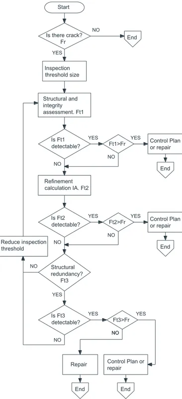
The methodology for the structural integrity assessment can be followed in the flowchart gathered in Figure 2. First, the crack size that can be detected during the inspection of the structure is established. Initially it is considered that the inspection of the bridge will be visual and, therefore, a defect size compatible with this type of inspection is established. For this study, and as an initial reference, it will be assumed that the crack size that can be detected by visual inspection in a singular steel structure would be in the range of 10 to 20 cm.
This will be the inspection threshold size to be considered initially in the method. In the case that the subsequent structural integrity analysis (following BS7910) determines that the critical crack size is smaller than the inspection threshold, a more accurate inspection method should be considered.
Once the critical crack size is obtained (Ft1), it is determined whether it can be detected by visual inspection
according to the established inspection threshold. If the critical crack is detectable, two situations can occur: the actual crack is larger than the critical crack or smaller than the critical crack. If the actual crack is larger than the critical crack (Fr>Ft1), a modified structural integrity evaluation (refinement of the calculation) will be applied to obtain a new
critical crack size (Ft2). If the actual crack is smaller than the critical one (Fr<Ft1), a control plan or, if necessary, a
repair plan for the crack will be established, ending the procedure.
The structural integrity refinement is less conservative than the basic one, providing larger critical crack sizes that could already be detected by visual inspection. In case the refined critical crack is detectable, it is compared to the real crack. If the real crack is smaller than the theoretical one (Fr<Ft2), a control plan or, if applicable, a repair plan for that
crack is applied, concluding the procedure. If the real crack is larger (Fr>Ft2), the redundancy of the structure will be
analysed in order to obtain a new critical crack size. In case the obtained critical crack is not detectable with the established visual inspection threshold, the redundancy of the structure is analysed in order to assess whether it is
possible to consider larger critical crack sizes (Ft3). Once again, it is necessary to check whether the critical crack
obtained is detectable by visual inspection methods or not.
Figure 2. Flowchart of the alternative structural integrity assessment methodology for steel bridges.
Start Is there crack? Fr NO YES End Structural and integrity assessment. Ft1 Is Ft1 detectable? YES NO Refinement calculation IA. Ft2 Structural redundancy? Ft3 Reduce inspection threshold Inspection threshold size Ft1>Fr NO NO Repair NO Ft2>Fr NO NO NO Ft3>Fr NO
YES YES Control Plan
or repair End Is Ft2 detectable? YES Control Plan or repair End End YES YES Is Ft3 detectable?
YES Control Plan
or repair End
If it is detectable, it is compared to the real crack. If the real crack is smaller than the critical one (Fr<Ft3), a control
plan or, if necessary, a repair plan will be applied to the crack, concluding the procedure. If the real crack is larger (Fr>Ft3), a repair plan is mandatory and the procedure concludes.
Finally, if Ft3 is not detectable with the established inspection threshold, it is necessary to reduce this threshold for
the specific structure or structural detail, thus making it possible in that case to detect cracks of smaller size. From there, the analysis cycle starts again.
The different aspects that should be addressed in the refinement of the analysis are explained below.
4.1. Modified structural integrity assessment technique
The refinement of the structural integrity assessment is based on the specifications of BS7910, with the following design and testing criteria:
Refined FAD.
Real tensile properties. Real fracture toughness.
Consideration of working temperature. Detailed calculation of residual stresses.
4.1.1. Refined FAD according to BS7910
BS7910 [4] has three levels of analysis depending on the application and availability of material data. Option 1 is a conservative procedure, relatively simple to apply and does not require detailed stress-strain data for the materials being analysed. Option 2 is based on the use of the full stress-strain curve of the material, providing less conservative results. Option 3 uses numerical analysis to generate the FAD, whose Failure Assessment Line (FAL, see Figure 1) is specific to the material, geometry and loading type.
The proposed methodology firstly considers the FAD defined in Option 1 and, for successive iterations the use of Option 2 and Option 3 FADs. As the analysis moves from Option 1 to Option 3, the final result (e.g., critical crack size) is more accurate and less conservative, but in contrast, the costs of the calculation and operational processes are higher. Options 2 and 3 are more costly to implement than Option 1, as they require specific laboratory testing and/or simulation.
4.1.2. Real tensile properties
From the inspection and maintenance point of view, and in this case, from the safety point of view, the traceability of the materials used in the bridge, such as concrete, reinforcing steel and, of course, structural steel, is considered to be essential. When refining the analysis, the actual tensile properties of the materials used on site can be obtained. In the case of steel plates, the whole stress strain curve and both the yield stress and the ultimate tensile strength can be taken into account for the calculations. These values are higher than those indicated in the specifications, something that implies an increase in the load bearing capacity of the structure. On the other hand, since these are real data, they are not affected by the coefficient of reduction of the mechanical properties required by the limit state calculation method. Finally, if the analysis considers an accidental situation, the standards also allow a value of 1.0 for the coefficient of reduction of the mechanical properties.
4.1.3. Real fracture toughness
When performing conventional bridge structural integrity assessments, conservative estimations of toughness obtained from Charpy results are generally used. Even in the case of using real toughness data, it is a conservative common practice to use the lowest fracture toughness value obtained in the tests. This is of particular relevance when assessing welded joints, where the fracture toughness of base material, heat affected zone (HAZ) and weld bead may be rather different.
Thus, the refinement in the use of fracture toughness data consists in using specific toughness values for the situation being analysed: e.g, if the crack is located in the base material, the fracture toughness of the base material should be used (and not lower values obtained from the HAZ of the weld bead). Similarly, if the number of tests performed in the particular location of interest is high enough, a statistical treatment can be performed in order to derive the fracture toughness value associated to a certain probability of failure (e.g., 5%), rather than using minimum values.
4.1.4. Consideration of temperature
Fracture toughness tests are carried out at a specific temperature according to the recommendations established by the applicable regulations or, if necessary, according to the historical temperature records in the area.
In a first analysis, and from a conservative point of view, the fracture toughness tests of the material used in the "Constitución de 1812" Bridge, were carried out at a temperature of -20 ºC. However, the minimum temperature recorded in Cadiz since 1954 according to the Spanish National Meteorology Agency (AEMET) is -1.0ºC [8], so the fracture toughness tests performed [5] are conservative, as they were performed at a temperature that is much lower (19ºC) than the minimum recorded temperature at the bridge location. In other words, the fracture toughness of the material can be significantly higher when considering a temperature closer to the real operating temperature.
4.1.5. Detailed calculation of residual stresses
BS7910 [4] proposes a series of expressions to determine the residual stresses in different types of joints. The proposed methodology proposes to perform, when necessary, detailed calculations to determine the actual residual stresses in the joint being analysed.
4.2. Structural redundancy criteria
The NCHRP 406 report [9] provides guidance on whether a structure can be considered redundant or not. This report develops a methodology to ensure that a bridge has a minimum level of safety when the bridge is intact or after the failure of a component.
A bridge is considered safe if it: a) Provides a reasonable level of safety against failure of the first member. b) Does not reach its ultimate capacity under extreme load conditions. c) No major deformations occur under expected load conditions. d) Is capable of supporting some traffic load after the damage of a component.
The report establishes four limit states to be reviewed when evaluating structural redundancy in bridges:
1. One member failure, load factor LF1. Live load in a linear elastic model, increasing the live load until the
failure of the first member.
2. Ultimate limit state, load factor LFu. Live load in a non-linear structural model, increasing the live load until
the bridge collapses.
3. Functionality limit state, load factor LFf. Live load in a non-linear structural model, increasing the live load
until the displacement in a main longitudinal member is L/100 (L being the main structural dimension). 4. Limit state of damage condition, factor LFd. Live load in a non-linear structural model, increasing the live
load until the bridge collapses.
Based on different reliability analyses, a bridge can be considered sufficiently redundant if the structural analysis provides the reserve ratios indicated in Table 1 [9]:
Table 1. Required load factor ratios [9]
LOAD FACTOR RATIOS FOR DIRECT SYSTEM REDUNDANCY APPROACH Reserve ratio Ultimate limit state Ru = LFu/LF1 1.30
Reserve ratio Functionality limit state Rf = LFf/LF1 1.10
The reserve ratio for damage condition Rd, with a value of 0.5, indicates that a damaged bridge must be capable of
supporting 50% of the live load of an intact bridge before failure of the first member occurs. The NCHRP 406 report [9] sets out criteria for establishing whether a bridge can be considered redundant or not and determines its level of redundancy. In this work, it is not a question of establishing whether a bridge is redundant or not, but to determine whether a bridge is in a safe situation according to the established redundancy criteria.
Thus, the methodology proposed in this document to justify the safety of a bridge in the event of a structural element failure, focuses on checking that the reserve ratio of the damage condition is admissible.
In addition, structural redundancy criteria will be followed, when necessary, to determine the actions and deformations to be considered in the analyses.
4.2.1. Actions considered
Currently, bridge design codes do not provide a definitive answer as to the level of load bearing capacity that a damaged structure must withstand.
One of the design conditions of the IAP-11 standard [10] is accidental situations, which are defined as those conditions that can be caused by an impact or the failure of an element. They shall be considered instantaneous unless the failure can remain undetected. The IAP-11 standard [10] evaluates the accidental situations considering the dead load and the live load, both without factoring.
The AASHTO LRFD specification [11], article 6.6.2, provides some ideas: “Relief from the full factored loads
associated with the Strength I Load Combination should be considered, as should the number of loaded design lanes versus the number of striped traffic lanes”. This may lead to unexpected situations, as the design lanes may be
temporarily put into service due to bridge damage.
The NCHRP 406 report [9] suggests that the required load should be unfactored, considering the dead load plus two HS-20 trucks in parallel, which can be considered more reasonable.
Moreover, the energy released during the fracture of steel elements must be taken into account in the calculations. A similar situation is envisaged in the design of cable-stayed bridges, which must be able to withstand the loss of a cable.
Following the structural redundancy criteria of the NCHRP 406 report [9], within the scope of the methodology proposed in this study for the particular case of the “Constitución de 1812” Bridge, it will be verified that the bridge has sufficient capacity to withstand the design stresses (dead loads + two H20 trucks + distributed service load), values that are not factored.
4.2.2. Limit deformations
Bridge design standards do not refer to the deformations to be considered when evaluating a damaged bridge. The NCHRP 406 [9] report proposes that, in service and with unfactored load, the maximum limit deflection should be lower than L/100, given that exceeding this value would make the bridge unsuitable for traffic.
The value of L/100 is also considered here as a limit in the case of a damaged bridge.
4.3. Calculation models
The analysis of the structural redundancy of a bridge requires the use of a structural model and a finite element package that considers the elastic and inelastic behaviour of the materials, as well as the possibility of second order geometric effects. The non-linear model can be used both for the analysis of an intact structure and for the study of different damage scenarios.
4.4. Structural integrity assessment of the “Constitución de 1812” Bridge. Cádiz
Following the methodology outlined above, an attempt will be made to justify that the permissible crack sizes are detectable by visual inspection. Larger defect sizes may be justified by structural redundancy criteria, using calculation
models to check that stability exists, that the deformations are maintained according to the defined criteria and that the remaining section meets the elasticity criteria.
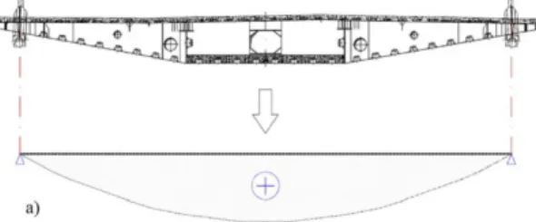
Figure 3. Bending moment diagram scheme in diaphragms of the deck with stay cables, working as simply supported beams.
In a first approach, the deck of the "Constitución de 1812" Bridge works in two different ways, depending on whether or not there are stay cables nearby. In those sections with stay cables, the transmission of forces and moments occurs perpendicular to the deck. This means that the transversal diaphragms act as simply supported beams that conduct the loads from the center of the deck to the stay cables. Thus, both the concrete slab and the upper part of the diaphragms are in compression, whereas the lower steel plates of the deck are subjected to (transverse) tensile stresses (see Figure 3). In contrast, those sections of the deck without stay cables work in approximately the same way as one or two span beams supported by the piers and/or by the stay cable zones. These beams usually present longitudinal negative bending moments on the supports and longitudinal positive bending moments in the central zone of the spans (see Figure 4).
As an initial approach, the structural integrity assessment of the "Constitución de 1812" Bridge will be carried out as follows:
1. In the extreme segments of the compensation spans, where there are areas without cables (see Figure 4) the plates 1, 2, 3 and 4, see Figure 5, are in charge of supporting the positive longitudinal bending moments. In this area, a transversal crack will be considered in a section of plate 1 and in a section of plate 4.
2. In the segments near the main towers, where there are areas without cables, plates 2 and 3 support part of the negative longitudinal bending moments. In this section, a transversal crack in plate 3 will be considered. 3. In areas with cables, see Figure 3, plates 1 and 4 are responsible for supporting the positive transverse bending
moments. In these areas, a longitudinal crack in a section of plate 1 or a crack in a section of plate 4 is considered.
Figure 5. Transversal section of the deck and identification of the steel plates.
5. Conclusions and future work
An initial structural integrity assessment of the steel deck of the "Constitución de 1812” Bridge obtained critical crack sizes that cannot be detected by visual inspection. As visual inspection is the typical inspection technique in bridges, this result represents a major structural integrity issue.
Moreover, ordinary structural integrity assessments (as that performed in the "Constitución de 1812” Bridge) are generally based on conservative assumptions that, consequently, generate conservative estimations of critical crack sizes.
This paper presents an alternative structural integrity assessment methodology for bridges to justify larger critical crack sizes. The proposed methodology is based on using more refined (less conservative) calculation options, according to BS7910 [4], and considering structural redundancy criteria such as the value of the stresses to be considered, the admissible level of deformation, etc. The final objective is to be able to demonstrate that, if it is physically true, the size of the estimated critical defects can be detected by visual inspection.
The methodology is currently being applied to the "Constitución de 1812” Bridge, over the Bay of Cádiz.
6. Acknowledgments
The authors of this work would like to express their gratitude to the University of Cantabria for the financial support of the project “Aplicación de Técnicas de Integridad Estructural y Fiabilidad de Materiales en la Determinacion del Ciclo de Vida de Puentes Metalicos y Mixtos” (03.DI09.649), a programme of industrial doctorates, on the results of which this paper is based.
7. References
[1] Instrucción de hormigón estructural EHE-08, Ministerio de Fomento, Spain, 2008. [2] Instrucción de acero estructural EAE. Ministerio de Fomento. Spain, 2011.
[3] F. Pedrazo-Majárrez. Introducción al Puente de la Constitución de 1812 sobre la bahía de Cádiz, Hormigón y Acero 67, pp. 278-279, 2016.
[4] BS7910, Guide to methods for assessing the acceptability of flaws in metallic structures, BSI, London, 2013.
[5] M.A. Díaz García, S. Cicero, O.R. Ramos Gutiérrez. Structural integrity assessment of the welded joints of the constitution of 1812 bridge (Cádiz, Spain), Engineering Failure Analyiss 90, pp. 518-533, 2018.
[6] The Manual for Bridge Evaluation, American Association of State Highway and Transportation (AASHTO), Washington DC, 2011. [7] D. Mertz, Steel Bridge Design Handbook: Redundancy, (Vol. 9), U.S.Department of Transportation Federal High Administration,
Washington DC, 2015.
[8] http://www.aemet.es/es/serviciosclimaticos/datosclimatologicos/efemerides_extremos?w=0&k=and&l=5973&datos=det [9] M. Ghosn, F. Moses. NCHRP Report 406: Redundancy In Highway Bridge Superstructures, Transportation Research Board,
Washington, 1998.
[10] Instrucción sobre las acciones a considerar en el proyecto de puentes de carretera IAP-11, Ministerio de Fomento, Spain, 2011. [11] AASHTO LRFD Bridge Design Specifications, American Association of State Highway and Transportation (AASHTO), Washington
![Figure 1. Schematic showing a failure condition according to FAD methodology (BS7910 [4] Option 1)](https://thumb-us.123doks.com/thumbv2/123dok_es/6763715.266766/2.816.242.579.718.911/figure-schematic-showing-failure-condition-according-methodology-option.webp)