LPDQ: a self scheduled TDMA MAC protocol for one hop dynamic low power wireless networks
23
0
0
Texto completo
(2) Manuscript Click here to view linked References. LPDQ: a self-scheduled TDMA MAC protocol for one-hop dynamic low-power wireless networks Pere Tuset-Peiro1,4 , Francisco Vazquez-Gallego2 , Jesus Alonso-Zarate2 , Luis Alonso3 , Xavier Vilajosana1,4 1 Internet 2 M2M 3 Signal. Interdisciplinary Institute, Universitat Oberta de Catalunya C/ Roc Boronat 117, 08018 Barcelona, Spain. Department, Centre Tecnològic de Telecomunicacions de Catalunya Av. Carl Friedrich Gauss 7, 08860 Castelldefels, Spain. Theory and Communications Department, Universitat Politècnica de Catalunya Av. Esteve Terradas 7, C4-204, 08860 Castelldefels, Spain. 4 Berkeley. Sensors and Actuators Center, University of California Berkeley 403 Cory Hall #1774, 94720 Berkeley, United States. Abstract Current MAC (Medium Access Control) protocols for data collection scenarios with a large number of mobile nodes that generate bursty traffic are typically based on low-power listening (LPL) for network synchronization and FSA (Frame Slotted ALOHA) as the channel access mechanism. However, FSA has a MAC layer efficiency bounded to an upper limit of 36.8% due to contention effects, which reduces packet throughput and increases energy consumption. In this paper, we target such scenarios by presenting LPDQ (Low-Power Distributed Queuing), a highly efficient and low power MAC protocol. LPDQ is able to self-schedule data transmissions, acting as a FSA MAC under light traffic and seamlessly converging to a TDMA (Time Division Multiple Access) MAC under congestion. The paper presents the design principles and the implementation details of LPDQ using low-power commercial radio transceivers. Experimental tests demonstrate a MAC efficiency close to 99% which is independent of the number of nodes in the network and is fair in terms of resource allocation to nodes. Keywords: Internet of Things, Machine-to-Machine Communications, Medium Access Control, Low Power Wireless, Time Division Multiple Access, Radio Frequency Identification, Frame Slotted ALOHA, Distributed Queuing.. 1. Introduction The IoT (Internet of Things) [1] is a paradigm in which objects are augmented with sensors and actuators and integrated to the Internet through low-power wireless communications and standardized protocols [2] to enable interaction with humans and other machines in an M2M (Machine to Machine) context. Integrating objects with the Internet may be challenging due to available energy constraints and the need to have long-lasting network deployments [3]. It is widely known that the radio transceiver is the element that dominates energy consumption in wireless communication devices [4]. In particular, it is the MAC (Medium Access Control) layer that controls when the radio transceiver has to be powered on, either to transmit or receive, and Preprint submitted to Pervasive and Mobile Communications. November 5, 2013.
(3) thus determines the overall energy consumption. According to [5], the energy waste at the MAC layer comes from four sources: packet collisions, packet overhearing, idle listening, and protocol overhead. For that reason, it is key to design MAC protocols that are efficient in these terms. Two aspects need to be tackled in the design of an efficient MAC protocol [6]: network synchronization and channel access. Regarding the former, MAC protocols can be classified into synchronous or asynchronous depending on whether nodes have a common notion of time that determines the action to take, e.g., receive or transmit. Regarding the latter, MAC protocols can be classified into reservation-based and random access according to the availability of a schedule that determines which node should transmit at each instant. The decision between the different alternatives depends on the application requirements and certain trade-offs exist between network performance and energy consumption. For networks with static nodes and periodic traffic it has been shown that a time-synchronized approach combined with schedule-based communications, e.g., IEEE 802.15.4e [7] based on TSCH (Time Slotted Channel Hopping), leads to high network efficiency and low energy consumption [8, 9, 10] regardless of the number of nodes. However, for networks with a large number of nodes that are mobile and generate bursty traffic, such approach is suboptimal due to the energy required to create, distribute and maintain the network schedule. In these scenarios, which are common in the IoT domain (e.g., data collection), a better approach is to combine low-power listening for network synchronization [11] with random channel access to enable data transmission [12]. However, current random channel access protocols, e.g., those based on FSA (Frame Slotted ALOHA), are suboptimal in terms of both network performance and energy consumption due to the effects of contention. Several authors have presented mechanisms to minimize collision probability in FSA-based protocols [13], which typically rely on discovering how many nodes are present in the network, either a priori (building a tree previous to data transmission) or a posteriori (inferring the number of collisions in the current frame), and adapting the number of slots per frame based on the feedback. Yet, when nodes are mobile and generate bursty traffic both approaches are not optimal because the discovery process either reduces network data throughput (due to time required to build the tree) or increases node energy consumption (due to data packet collisions in subsequent frames). Considering the limitations of existing MAC protocols for such networks, in this paper we focus on the design, implementation and evaluation of LPDQ (Low-Power Distributed Queuing). The paper describes LPDQ, which is based on LPL (Low-Power Listening) for network synchronization and DQ (Distributed Queuing) for channel access, and includes CH (Channel Hopping) to add robustness against multi-path propagation and external interference. The paper also presents the implementation of LPDQ using off-the-shelf hardware and a custom software stack, and discusses its main challenges and the solutions that have been adopted. Finally, an experimental evaluation of LPDQ is also presented, demonstrating its performance and comparing it to FSA in terms of packet throughput. The main benefits of the LPDQ channel access mechanism compared to FSA are: a) No collisions during data packet transmission, b) Performance is independent on the number of nodes, and c) Resources are evenly distributed among nodes. To the best of our knowledge, this is the first paper that presents and evaluates the performance of a MAC protocol based on the principles described above for the IoT. Moreover, as far as we know, none of the current research includes experimental evaluation showing the feasibility of the MAC protocol when implemented using low-power commercial radio transceivers. The remainder of the paper is organized as follows. Section 2 presents the research related to improving the performance of FSA, as well as the research related to DQ. Section 3 presents the design principles and operational details of LPDQ. Section 4 discusses the implementation of LPDQ using off-the-shelf hardware and a custom software stack. Section 5 evaluates the 2.
(4) performance of LPDQ and compares it to FSA. Finally, Section 6 concludes the paper. 2. Related work This section presents the work related to our research and is divided into two subsections. The first subsection presents the research related to improving the performance of FSA, whereas the second subsection introduces DQ and presents the existing research related to it. 2.1. Frame Slotted ALOHA FSA is the channel access mechanism used by standards that need to support data collection scenarios where nodes are mobile and generate bursty traffic, e.g., ISO 18000 [14]. ISO 18000 is a family of standards targeted at RFID, e.g., item identification and management applications. The ISO 18000-1 standard defines the generic system architecture, whereas the remaining parts of the standard, e.g., ISO 18000-2 to ISO 18000-7, define the physical layer and data-link layer parameters to operate at different frequency bands, e.g., 135 kHz, 13.56 MHz, 2.45 GHz, 868915 MHz, and 433 MHz. In particular, the data-link layer of ISO 18000-7 [15], which is targeted at active RFID operating in the 433 MHz band, uses LPL to wake-up nodes and FSA to enable data transmission. However, due to the effects of contention, e.g., two nodes transmitting in the same slot, the maximum performance of FSA is 36.8% only when the number of slots per frame is equal to the number of contending nodes [13]. To improve the performance of FSA, several authors have proposed various methods based on two principles. First, using a tree splitting algorithm to detect the number of nodes present in the network a priori, e.g., previous to data transmission. Second, determining the optimal number of slots per frame a posteriori, e.g., based on the information extracted from collisions in the current slot. The different proposals that are available in the literature are summarized next. Yoon et. al. [16] propose two mechanisms to improve the tag anti-collision protocol. The first is based on a dynamic approach to enable the reader select the optimal slot size. The second is based on a broadcast command that enables to put tags to sleep more effectively. The results, based on real-world experiments, show that the collection time is directly proportional to the number of tags. In [17], Yeh et al. present ASPS (Adaptive Splitting and Pre-Signaling), a counter-based tag anti-collision protocol that uses adaptive splitting and pre-signaling to reduce tag collision. First, by means of predicting the number of tags it can split them into groups to reduce collision probability. Second, by means of using pre-signaling it is possible to reduce tag identification delay. The results obtained show that the MAC protocol achieves a maximum efficiency of 55%. Nilsson et al. [18] present and evaluate a contention-based MAC protocol for active RFID that uses a non-persistent CSMA/CA (Carrier Sense Multiple Access / Collision Avoidance) with a dynamic back-off window in a non-slotted channel. The paper studies energy consumption, read-out delay and message throughput based on computer simulations. The results show that it is possible to reduce the average energy consumption, leading to a 50 % increase in tag battery lifetime. In [19], Chin et al. present E2 MAC, an energy efficient MAC that uses a dynamic FSA with three different frame types to read and monitor tags. The results show that the protocol reduces the number of collisions and the energy wasted to resolve them. More recently, Namboodiri et al. investigate in [13] the effects of collisions in slotted ALOHA-based protocols for RFID and show that collisions have an impact on both the transaction time and the energy required to complete it. The authors derive a mathematical model of the protocol performance, validate it using simulations and, finally, evaluate it using an experimental 3.
(5) setup. In the experimental phase the energy consumption of both the reader and the tags is evaluated, confirming that the consumption is directly proportional to the number of tags present in the reader field. In [20], Qian et al. present ASAP (Adaptively Splitting-based Arbitration Protocol), a protocol that creates groups of tags on demand and estimates the cardinality of each group during this process. The authors perform both theoretical analysis and simulation evaluation to show that the performance of ASAP is better than other existing collision-arbitration protocols and the efficiency is close to the theoretically optimal values. Finally, Wu et al. [21] present a novel anti-collision protocol based on a binary tree slotted ALOHA, which allows to adjust the number of slots per frame to a value close to the number of tags. The results show that the MAC performance can be increased to 42%.. 2.2. Distributed Queuing DQ is a channel access mechanism that evolves from CTA (Collision Tree Algorithm) [22]. In CTA, the ternary feedback (e.g., empty, collision and success) obtained from the transmission of data packets is used to subsequently split nodes into sub-groups to reduce the collision probability of future data packet transmissions. In fact, using such approach it is possible to ensure that after a certain number of transmissions, which depends on the number of slots per frame and the number of nodes in the network, each node will be able to transmit without contention. In that sense, DQ improves over CTA in three different ways. First, DQ interleaves the contention resolution process with the transmission of data packets. Second, DQ uses smaller packets to obtain ternary feedback from nodes requesting access to the network. Third, DQ uses the feedback obtained to organize the nodes in two different queues, one to manage the subsequent resolution of collisions and the other to manage the transmission of data packets. Compared to CTA, using such approach enables DQ to minimize the effects of contention, thus leading to an increase in network performance and a reduction in the energy consumption of nodes. Originally, DQ was designed for the distribution of digital signals over wired networks, e.g., CATV (CAble TeleVision) [23]. However, over the years DQ has been adapted to the specific requirements of other types of networks, both wired and wireless. Regarding the latter, in DQRAP/CDMA [24] it was adapted for third generation cellular networks based on CDMA (Code Division Multiple Access). In DQCA [25, 26] it was adapted for WLANs (Wireless Local Area Networks). In DQMAN [27] it was adapted for MANETs (Mobile Ad Hoc Networks). Finally, in DQBAN [28] it was adapted for BANETs (Body Area Networks). In all cases DQ has been able to ensure collision-free data transmissions and offer a near optimum performance that is independent of the offered traffic and the number of nodes present in the network. This is specially interesting for data collection scenarios in the IoT, where there may be a large number of nodes that are mobile and generate bursty traffic patterns.. 3. Protocol design In this section we present LPDQ, a MAC protocol specifically suited for scenarios where nodes are mobile and generate bursty traffic. Specifically, we describe the operation principles of LPDQ and present the protocol operation details, making emphasis on the aspects that make it suitable for the targeted scenarios. 4.
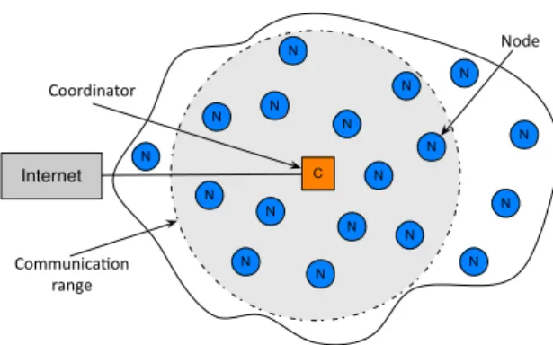
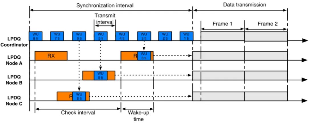
(6) Node. N. Coordinator. N. N N. N. N. N. N. N C. Internet. N. N. N. N N. Communica)on range. N. N. N N. Figure 1: Network topology with a coordinator and multiple nodes. 3.1. Protocol overview LPDQ uses a single-hop star topology with two device types, node and coordinator, as depicted in Figure 1. A node (or device) is a battery-operated device that includes a low-power radio transceiver that enables it to communicate with the coordinator. In addition, a node may contain sensors and actuators to monitor physical parameters or actuate over physical elements. On its behalf, a coordinator (or gateway) is the device responsible for triggering communications with nodes and interfacing with other networks, e.g., the Internet. As introduced earlier, LPDQ is based on three design principles: Low-Power Listening (LPL), Distributed Queuing (DQ) and Channel Hopping (CH). First, LPL is used for network synchronization and enables the coordinator to wake up nodes that are within its communication range. Second, DQ is used as the channel access mechanism and ensures that all each node knows exactly which action to take in each frame, e.g., receive or transmit a packet, and that all data transmissions in the network are collision free despite there is no network schedule. Third, CH is used to add robustness to the network against the effects of multi-path propagation and external interferences from other networks operating in the same band. Using these principles, the operation of LPDQ is divided in two phases: network synchronization and data transmission. These two phases are described in detail in the following subsections. 3.2. Network synchronization In LPDQ, communications are triggered by the coordinator, as depicted in Figure 2. The network synchronization phase is responsible for waking up all nodes that are within the coordinator communication range and synchronizing them to enable data transmission. By default, nodes are in a low-power listening mode in which they periodically wake up and turn on the radio transceiver for a short period of time to detect communication requests from surrounding coordinators. The period between two consecutive wake-up events is called check interval, whereas the time that the node remains in the wake-up state is called wake-up time. Upon detecting a command from upper layers, e.g., application layer, the coordinator starts broadcasting wake-up packets. The overall duration of the network synchronization phase is called synchronization interval. Within the synchronization interval, wake-up packets are transmitted at a rate called transmit interval and have a duration named transmit duration. Wake-up packets are formed by a short preamble and payload and, among other information, contain the time at which nodes are expected to enter the data transmission phase and, also, the channel offset at which nodes 5.
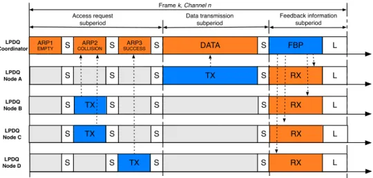
(7) Data transmission. Synchronization interval Transmit interval LPDQ Coordinator LPDQ Node A. WU 8 ti. WU 7 ti. WU 6 ti. Frame 1 WU 4 ti. WU 3 ti. WU 2 ti. Frame 2. WU 1 ti. RXWU 3 ti. RX WU RX 5 ti. LPDQ Node B LPDQ Node C. WU 5 ti. WU. RX 6 ti. Check interval. Wake-up time. Figure 2: Example: network synchronization using low-power listening. Node C receives the wake-up packet when 6 ticks remain, whereas Node B receives it when 5 ticks remain and Node A receives it when only 3 ticks remain. However, because all nodes share the same notion of time, they will wake-up simultaneously to start the data transmission phase.. are expected to start communicating. Thus, when nodes receive a wake-up packet from a coordinator they configure a time event to wake up at a specific moment in time and enter the data communication phase, which is described in the following subsection. The timing of the network synchronization phase, that is, the time at which nodes enter the receive mode as well as its duration, and the channel that nodes listen to is configurable. However, all the nodes that are in the network must share the same notion of time and configuration parameters in order to be able to synchronize with a coordinator. In that sense, a tick is defined as the minimum unit of time at which events can be resolved at the MAC layer. In addition, there are two constraints that need to be met in order to ensure that all nodes within the coordinator communication range will receive at least one wake-up packet. First, the coordinator synchronization interval has to be longer than the node check interval. Second, the coordinator transmit interval has to be shorter than the node wake-up time. 3.3. Data transmission In LPDQ the data transmission period operates in a synchronous basis using a time-fixed frame structure that repeats over time until communications are completed, e.g., when nodes have no further data packets to be transmitted to the coordinator. At each frame, three time-fixed subperiods are defined: access request, data transmission and feedback information, as depicted in Figure 3. The aim of the access request subperiod is to enable nodes to request network access by means of transmitting an ARP (Access Request Packet). The aim of the data transmission subperiod is to enable nodes to transmit a data packet to the coordinator without contention. Finally, the aim of the feedback information subperiod is to enable the coordinator transmit a FBP (FeedBack Packet) that provides nodes with information regarding the status of the access request and the data transmission subperiods, e.g., data positive or negative acknowledgement. In addition, a SIFS (Short Inter-Space Frame) and LIFS (Long Inter-Space Frame) are introduced to compensate for random delays, e.g., data processing. 6.
(8) Frame k, Channel n Access request subperiod LPDQ Coordinator. ARP1 EMPTY. S. ARP2 COLLISION. S. Feedback information subperiod. Data transmission subperiod ARP3. S. DATA. S. FBP. L. S. S. TX. S. RX. L. SUCCESS. LPDQ Node A. S. LPDQ Node B. S. TX. S. S. S. RX. L. LPDQ Node C. S. TX. S. S. S. RX. L. LPDQ Node D. S. S. S. RX. L. S. TX. Figure 3: Data transmission using a time-fixed structure with access request, data transmission and feedback information subperiods. Example: in the access request subperiod the ARP1 is empty (no node transmits an ARP), the ARP2 is collision (Node B and Node C transmit an ARP, so they will join the CRQ) and ARP3 is success (only Node D transmits an ARP, so it will join the DTQ). In the data transmission subperiod Node A transmits its data packet because it is at the head of the DTQ. Finally, in the feedback information subperiod the coordinator transmits a FBP that is received by all nodes. Note that S stands for SIFS and L stands for LIFS.. In order to ensure collision-free data transmission, two distributed queues are used; one to organize nodes that need to resolve their collisions during the access request subperiod (CRQ, Collision Resolution Queue) and another to organize nodes that have successfully entered the system and are awaiting to transmit their data packet to the coordinator (DTQ, Data Transmission Queue). Both queues are distributed in the sense that each node only has two integer numbers representing each queue; one number that represents the total length of the queue (same value in all nodes) and another number that represents the relative position of the node within the queue (different for each node). The resolution of collisions within the CRQ is done using a BTSA (Blocked Tree Splitting Algorithm) and a set of rules, e.g., a node can only transmit an ARP if the CRQ is empty and it does not hold any position in the DTQ. A detailed overview of the protocol operation, including the set of rules that determine how queues are managed and how nodes behave under each situation, can be found in [25]. The access request subperiod is further divided into a configurable number m of ARP slots, and it is used by the nodes to request access to the network. To do so, they select an ARP slot at random and transmit an ARP. The coordinator operates in receive mode for the complete access request subperiod and listens to the ARPs transmitted by nodes. According to the outcome of each ARP slot, the coordinator can distinguish between three states: empty, success or collision. An ARP slot is empty if no node has transmitted an ARP in that slot. An ARP slot is declared successful when a single ARP has been received and decoded. Finally, a collision occurs when two or more nodes transmit in a particular ARP slot and none can be decoded by the coordinator. Nodes that succeed in transmitting an ARP enter the DTQ, whereas nodes that collide enter 7.
(9) the CRQ. Using such approach, nodes are progressively separated into smaller groups and the process is repeated in every frame until all nodes are queued in the DTQ. Therefore, collisions in LPDQ can only happen during the access subperiod and are used to organize nodes into the CRQ or DTQ depending on the ARP outcome. This implies that the energy wasted due to collisions is reduced in LPDQ with regard to other MAC protocols that use data packets to contend because collisions only happen with ARPs, which are shorter than data packets. Moreover, BTSA ensures that in every frame a maximum number of m nodes can solve their previous ARP collision and enter the DTQ. This approach reduces the average number of ARP transmission attempts required by each node to enter into DTQ logarithmically. The data subperiod is used by the node at the head of the DTQ, i.e., at the first position, to transmit its data packet to the coordinator. The outcome of a data packet in the data subperiod is threefold: success, empty or error. Success indicates that the coordinator received the data packet successfully. Empty indicates that no data packet was detected in the current data subperiod. Finally, error indicates that the data packet could not be properly received, e.g., it did not pass the CRC (Cyclic Redundancy Check). As only one node can hold the first position of the DTQ at any given time, LPDQ ensures that data packets are transmitted without contention. Besides, LPDQ is protocol agnostic, meaning that the data packet is able to transport any type of upper layer protocol. For example, a data packet can have a 6LoWPAN (IPv6 over Low power Wireless Personal Area Networks) header, thus allowing IP addressing. Moreover, because LPDQ is designed for one-hop communications, routing protocols at the network layer are not required, e.g., RPL (Routing Protocol for Low-Power and Lossy Networks) [29]. To enable communications with other networks, e.g., the Internet, the coordinator can actuate as a gateway implementing any address translation or routing protocol, and forwarding data accordingly. The feedback subperiod is devoted to transmitting the feedback packet. The feedback packet is broadcast by the coordinator and must be received by all nodes that are currently part of the network. The feedback packet contains information regarding the status of each ARP slot in the access subperiod, e.g., empty, success or collision, and the data packet in the data subperiod, e.g., success, empty or error. Based on the information received in the feedback packet, nodes are able update their relative positions in the CRQ and DTQ. For example, if a node transmitted an ARP with success, it will enter the DTQ at the last position. Contrarily, if the ARP collided, the node will enter the CRQ at the last position. Also, if the data packet in the data subperiod was successful, the node will leave the DTQ, enabling the next node to transmit its data packet in the subsequent frame. The feedback packet also includes the current values of the CRQ and the DTQ to enable nodes ensure that their local values are consistent with the whole network and allow the recovery of nodes that may have lost one of the feedback packets. Finally, the feedback packet also includes a field that determines the end of the current collection period. Such condition occurs when the coordinator detects a certain number of frames without receiving any ARP and the DTQ being empty, i.e., neither new access requests nor data pending to be transmitted. Finally, because LPDQ may operate in unlicensed bands or multiple LPDQ networks may coexist in the same location, a mechanism to provide robustness against physical layer effects, e.g., multi-path propagation and external interference, is required. To provide robustness against such physical layer effects, LPDQ uses a slow channel hopping mechanism similar to that of IEEE 802.15.4e [7]. The available bandwidth, W, is divided into a number of equispaced channels, Nchannels . In the particular example of the IEEE 802.15.4e, Nchannels = 16, numbered from 0 to 15. The channel to be used in frame i + 1 is denoted by ci+1 and can be computed as ci+1 = [ci + S pattern ] (mod Nchannels ), 8. (1).
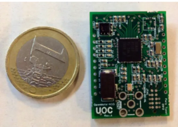
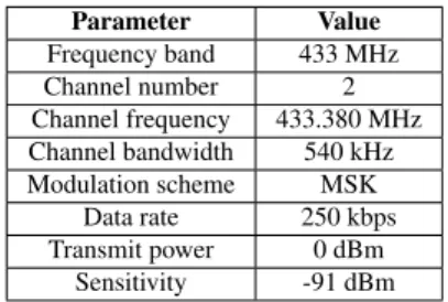
(10) where ci is the channel used in the previous frame i, and S pattern is a sequence pattern of integer numbers that is included by the coordinator in the wake-up packets during the synchronization phase. This sequence can be randomly generated by the coordinator for each collection round to provide the system with higher reliability. Note that a node which does not know and follow the sequence will not be able to interfere the network set by a given coordinator. 4. Protocol implementation This section presents the implementation details of LPDQ, including both the hardware platform and the software stack that have been developed, as well as the configuration parameters that have been used. In addition, the section presents the implementation challenges that have been found during the implementation and discusses how these challenges have been addressed. 4.1. Hardware platform To implement and evaluate LPDQ we have developed OpenMote-433, a COTS (Commercial Off-The-Shelf) low-power wireless platform. OpenMote-433, depicted in Figure 4, is based on a Texas Instruments CC430 SoC (System on Chip) [30], which embeds an MSP430 16-bit RISC microcontroller, running at 16 MHz with 4 kBytes of RAM and 32 kBytes of Flash memories, and a CC1101 radio-transceiver, which operates at the Sub-GHz band with data rates of up to 600 kbps and supports ASK (Amplitude Shift Keying), FSK (Frequency Shift Keying) and MSK (Minimum Shift Keying) modulations. The radio transceiver has been tuned to the 433 MHz band using a discrete balun and connected to a λ/4 monopole antenna through an SMA connector. Finally, two AAA batteries provide energy to the system (3 V, 1500 mAh).. Figure 4: An OpenMote-433 board with a Texas Instruments CC430 SoC.. 4.2. Physical layer LPDQ is independent of the physical layer and thus can operate in any frequency band, at any data rate, and with any modulation scheme. In the particular implementation described in this paper, and in order to maximize the transmission range to guarantee single-hop communications, we have implemented LPDQ to operate at the 433 MHz band. This is the band of operation defined in the specification of the 9.
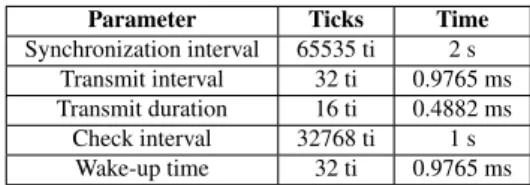
(11) Parameter Frequency band Channel number Channel frequency Channel bandwidth Modulation scheme Data rate Transmit power Sensitivity. Value 433 MHz 2 433.380 MHz 540 kHz MSK 250 kbps 0 dBm -91 dBm. Table 1: LPDQ physical layer parameters. IEEE 802.15.4f amendment [31] to the IEEE 802.15.4 standard [32], which is targeted at active RFID applications, e.g., data collection scenarios. This amendment defines three possible data rates, i.e., 31, 100 and 250 kbps, and a type of continuous phase FSK modulation called MSK. For our implementation, we have used a data rate of 250 kbps, which yields a measured sensitivity of -91 dBm for a PER (Packet Error Rate) of 1% transmitting packets of 20 bytes and using a channel bandwidth of 540 kHz. This data rate has been selected because it is equivalent to that of IEEE 802.15.4 and achieves the least energy consumption per bit while offering a range that has been measured to be 1.6 times that of the 2.4 GHz band in real conditions [33]. In case that a longer range is required, the lower data rates defined in the standard, e.g., 31 kbps or 100 kbps, can be selected at the expense of increasing the energy consumption per bit if the transmit power is kept constant. 4.3. Network synchronization phase Regarding network synchronization, the implementation of low power listening on both the coordinator and the nodes has been realized using the microcontroller hardware. The time reference has been obtained from the internal real-time clock (RTC), which operates at 32,768 kHz. Therefore, the minimum time unit at which events are resolved is referred to as a tick and its duration is equal to 30.51 us (1/(32,768 kHz)). Upon the reception of a command from the application layer, the coordinator initiates the synchronization phase. A timer is configured to periodically generate an interrupt that wakes-up the microcontroller. Upon wake-up, the microcontroller configures the transceiver and transmits a wake-up packet that has a duration of transmit duration. After the wake-up packet has been transmitted the microcontroller puts the transceiver back to sleep mode until the next wakeup event defined by transmit interval. The process is repeated until the total duration of the synchronization phase expires, which is defined by synchronization interval. On the node side, the timer is configured to periodically generate an interrupt that wakes-up the microcontroller (check interval). Upon wake-up, the microcontroller configures the radio transceiver and puts it in receive mode for a certain amount of time (wake-up time). Once the wake-up event expires, the microcontroller puts the transceiver back to sleep mode until the next wake-up event. If a wake-up packet is successfully received from the coordinator when the transceiver is in receive mode, the node schedules the beginning of the next data transmission phase (indicated in the wake-up packet) by configuring a timer interrupt and goes back to sleep. The interrupt will wake up the node to start the data transmission phase at the right time. The network synchronization parameters that describe the operation of the coordinator and the nodes are summarized in Table 2. With such configuration parameters, the node radio duty cycle during the synchronization phase has a value of approximately 0.1%, which yields an average 10.
(12) Parameter Synchronization interval Transmit interval Transmit duration Check interval Wake-up time. Ticks 65535 ti 32 ti 16 ti 32768 ti 32 ti. Time 2s 0.9765 ms 0.4882 ms 1s 0.9765 ms. Table 2: LPDQ network synchronization parameters. Parameter Access subperiod Data subperiod Feedback subperiod SIFS LIFS Total. Ticks 28 ti 168 ti 42 ti 16 ti 32 ti 390 ti. Time 0.85 ms 5.12 ms 1.28 ms 0.488 ms 0.976 ms 11.9 ms. Table 3: LPDQ data transmission parameters.. energy consumption of 30 uA on our platform. With a battery capacity of 1500 mAh, a node can remain alive in the network synchronization phase for 5 years. 4.4. Data transmission phase Regarding data transmission, the implementation of the frame timing on both the coordinator and the nodes has also been realized using the microprocessor RTC, attaining the same tick resolution. As described earlier, there are three fixed-time subperiods in each frame: access request, data transmission, and feedback information. The parameters that characterize and describe the duration of each subperiod are summarized in Table 3. Taking into consideration these parameters, LPDQ operates at a rate of 84 frames/second. The number of ARP slots, m, within the access subperiod can be arbitrary chosen and determines the speed at which collisions can be resolved. Xu et al. demonstrated in [34] that setting m = 3 is sufficient to ensure the stability of the protocol by resolving collisions in the access request subperiod faster than the actual transmission of data packets. Increasing the number of slots has minimal impact on the performance of the collision resolution mechanism but extends the duration of the frames at no gain. Therefore, we have set m = 3 in our implementation. Regarding the data transmission subperiod, it is important to note that with the chosen timing configuration and selected data rate, as presented earlier, the data packet is able to transport a payload of up to 127 bytes. Such configuration makes LPDQ fully compatible with standardized protocols for the Internet of Things [2], i.e., 6LoWPAN frames and other upper layer protocols such as CoAP (Constrained Application Protocol). Finally, it is important to remark that all nodes must receive each FBP to maintain synchronization and properly update the values of CRQ and DTQ. Therefore, nodes apply a simple mechanism to detect possible synchronization losses and to correct them, e.g., when a FBP is not received due to multi-path propagation or external interference. The mechanism makes use of a counter that is initialized to a predetermined value. This counter is decreased by one unit every time a FBP is not received. In such case, the node also resets the value of CRQ and DTQ to avoid interfering with other nodes. If the counter reaches zero, the node considers that it has lost communication with the coordinator and returns to the synchronization phase. 11.
(13) 4.5. Implementation challenges Four main challenges had to be resolved to operate LPDQ in a robust manner. These challenges are described in the next subsections. 4.5.1. Time synchronization Compared to FSA, LPDQ has much strict timing requirements because within each frame five different events occur: an ARP subperiod with m = 3 ARP slots, a data subperiod with a data slot and, finally, a feedback subperiod. Attaining such a granular synchronization poses a severe challenge because loosing synchronization can lead to interference in the protocol behavior, e.g., a node transmitting out of the slot bounds. There are three aspects related to time synchronization that had to be taken into account along the implementation process: 1. Clock drift. Due to physical characteristics of the crystals used to source the microcrontroller RTC, e.g., construction, temperature, aging, etc., the ticks of the clock may have a relative drift between nodes. In order to compensate this drift, each node aligns its clock in the data transmission phase when it receives the feedback packet from the coordinator. With this approach it is possible to achieve a per-frame network-wise synchronization of ±1 tick or ±30.51 us with the coordinator. This is sufficient to ensure that crystal characteristics do not interfere with the protocol timing. Other techniques to cope with clock drift due to temperature effects have been recently reported in [35]. 2. Turn-around times. The delay to turn on and off the radio transceiver and the time it takes to change from one state to the other, e.g., from idle to receive or transmit and viceversa. These delays are caused by the time it takes for the radio transceiver clock to stabilize. Since these delays are deterministic, or have a worst case response time, it is possible to measure the worst case condition of each delay using a logic analyzer and compensate them in the firmware. For example, in our implementation, an event that needs to change the radio transceiver state from idle to receive is compensated by 4 ticks or 122 us, which is enough to be in accordance with the CC430 datasheet [30]. 3. Processing delays. The time it takes the microcontroller to prepare a packet to be transmitted or to process the data received from the radio transceiver, and to take action based on it, is not deterministic. Moreover, this time is different for nodes and the coordinator because they process data differently. For instance, nodes need to execute the protocol rules after receiving a feedback packet from the coordinator. To compensate for these delays, we have included a SIFS after each ARP slot in the access subperiod and after the data packet in the data subperiod, and a LIFS after the feedback packet in the feedback subperiod. This ensures that both the coordinator and the nodes have enough processing time. 4.5.2. ARP selection The selection of ARP slots by the nodes has to meet two properties to ensure that the resolution of ARP collisions is logarithmic with a base equal to the number of ARP slots in the access subperiod: 1. It has to follow a uniform distribution, e.g., all the ARP slots must have the same probability to be selected. 2. It must have no memory, e.g., the selection of the next ARP slot shall not depend on the previously selected ARP slot. 12.
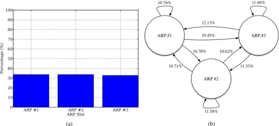
(14) 11.68%. 10.76%. 100 90. 12.13%. 80 ARP #1. Percentage (%). 70 60. 10.45%. 10.70%. ARP #3 10.62%. 50 40. 10.71%. 30. 11.33%. ARP #2. 20 10 0. ARP #1. ARP #2 ARP Slot (a). ARP #3. 11.58%. (b). Figure 5: Selection and transition properties of the ARP selection mechanism based on a Galois LFSR.. The mechanism to select the ARP in nodes is based on a PRNG (Pseudo-Random Number Generator). In order to obtain a truly random process, we obtain the seed for the PRNG by reading the noise level at input of the ADC (Analog-to-Digital Converter). Then, the pseudorandom sequence is generated using a Galois LFSR (Linear-Feedback Shift Register). A simple experiment has been conducted to check the suitability of this approach. A single node selects an ARP slot at random within the access request subperiod and transmits an ARP to the coordinator. The process is repeated 25.000 times and the state probability, e.g., the probability of selecting each ARP, and state transition probabilities, e.g., the probability of selecting an ARP depending on the ARP previously selected, are computed. The results obtained, shown in Figure 5, validate the good operation of such mechanism. However, it is worth noting that if two or more nodes generate the same initial seed, then all the pseudo-random numbers that will be generated using the Galois LFSR will be exactly the same. Thus, the nodes will select the same ARP slots again and again, resulting in continuous ARP collisions. This situation would lead to nodes not being able to join the DTQ and therefore, not being able to transmit their data packets. To solve this problem our implementation ensures that a new seed is generated every time a node collides in the transmission of an ARP. 4.5.3. Collision detection Detecting collisions in the access subperiod is a great challenge. Radio transceivers have not been specifically designed for such purpose, but to provide robust data transmissions. However, the proper operation of the BTSA, and thus LPDQ, depends on the successful detection of whether each ARP is either success, empty or collision, to enable nodes join the appropriate queue; the CRQ in the case of ARP collision and the DTQ in the case of ARP success. Ideally, the state of an access request slot, e.g. idle, success, or collision could be established by determining i) the presence or absence of a physical layer preamble (note that all data packets must have attached a preamble to enable synchronization at the receiver side), and ii) the amount 13.
(15) of energy present in the channel for the duration of an ARP, i.e., the RSS (Receiver Signal Strength). In the latter case, a threshold must be defined to determine when the channel is considered to be either occupied or idle. According to these two criteria, the following four situations can occur: • Preamble detected and RSS above the threshold; in this case, a success is claimed. • Preamble detected but RSS below the threshold; in this case, a collision is claimed. • Preamble not detected and RSS above the threshold; in this case, a collision is claimed. • Preamble not detected but RSS below the threshold; in this case, an empty is claimed. In our implementation, we have set the RSS threshold at -80 dBm. In order to define this value, we have analyzed the noise level present in the channel using a spectrum analyzer to ensure that the false positive rate, defined as the probability that a collision is detected when the ARP slot is actually empty because no node transmitted an ARP, is negligible. Unfortunately, real world implementation shows that artifacts such as clock drifts, transmission delays, or propagation effects, make the status detection more difficult. In particular: 1. Lack of synchronization. Assuming that nodes are synchronized to a clock with a 1 tick resolution, and considering that two nodes can have a maximum relative drift of 2 ticks, e.g., 61 us, a node can start transmitting its ARP up to 61 us earlier than another node. Therefore, the coordinator will receive the preamble of a node before the preamble of the other, detecting a successful ARP transmission when, indeed, a collision has occurred. 2. Capture effect [36]. The coordinator can receive the transmissions from two nodes with different RSS values due to either their different location or the effects of multi-path propagation. Therefore, the coordinator will receive the signal from the closest node with higher RSS, treating the signal of the furthest node as noise or interference. Again, a successful ARP slot will be announced when, in reality, a collision has occurred. In both cases the feedback provided by the coordinator will indicate that the ARP slot has been successful and the two nodes will enter the DTQ in the same position. This will lead to a collision in the data subperiod when both nodes get to the first position of DTQ simultaneously, yielding a degradation of the protocol performance. In order to overcome these two problems, LPDQ attaches the node UID (Unique IDentifier) and a CRC to each ARP. Therefore, once an ARP is received, a CRC check is performed. If the check is successful, then the node UID of the successful ARP is included in the feedback packet. However, if a preamble is correctly detected but the CRC check fails, then the ARP is considered to be collided and a null node UID is indicated in the feedback packet by the coordinator. Therefore, the detection of the status of the ARP slots becomes very reliable, avoiding the effects of the capture effect and the lack of perfect synchronization. It is worth mentioning that assuming an ideal configuration with m = 3 access slots, the inclusion of 3 UIDs in the FBP has no significant impact on the performance of the protocol, even though the overhead increases slightly. As an alternative to including the UIDs and thus reduce the overhead, it would be possible to include a random number computed per node per each transmitted ARP and making sure that the probability that two or more nodes select the same random number and select the same ARP slot in the same frame is negligible. Finally, it is important to remark that the inclusion of the UID and a CRC to the ARP is a workaround to the limitation posed by current radio transceivers which have not been designed 14.
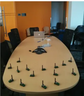
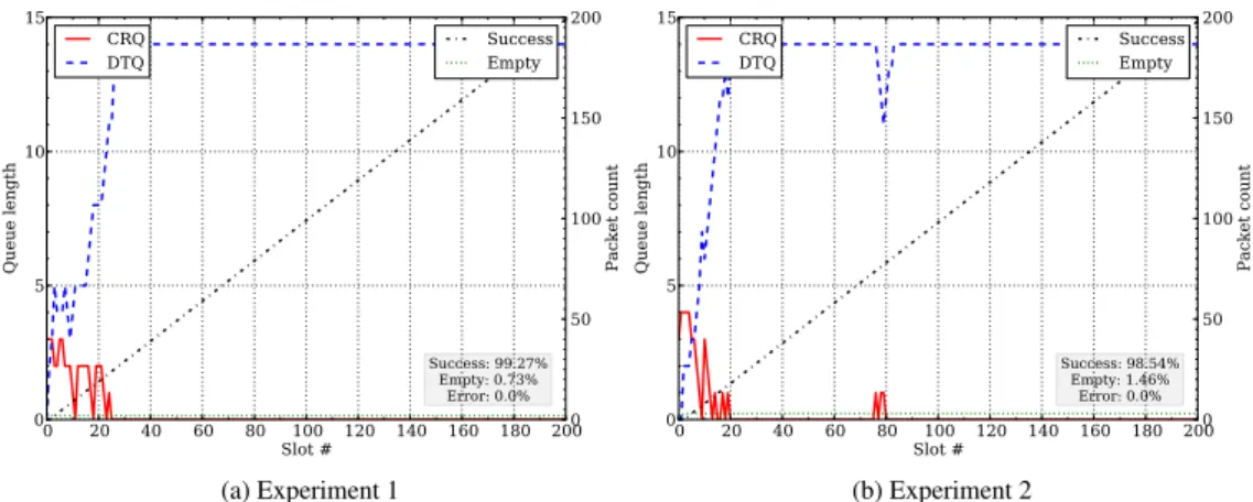
(16) to detect packet collisions. Instead, they have been designed to reliably transmit data and thus implement robust modulations that lead to the capture effect when two signals are received together. The availability of radio transceivers more capable of detecting collisions, such as those based on modulations based on phase would lead to communications less sensitive to the capture effect and would thus approach the performance of the protocol to its theoretical optimum. 4.5.4. Multi-path propagation It has been demonstrated that channel hopping at the 2.4 GHz band is able to combat both multi-path propagation and external interference effects [37]. On the one hand, multi-path propagation is caused by reflected radio-frequency signals, which are out-of-phase with the main signal propagation path. This phenomena may lead to destructive interference that reduces PDR (Packet Delivery Ratio). On the other hand, external interferences are caused by other networks operating in the vicinity at the same frequency band. Similarly, this phenomena may lead to a reduction in the PDR when listen-before-talk mechanisms are not implemented. However, at the Sub-GHz bands, it has been demonstrated that channel hopping can only combat the effects of external interferences. This is due to the fact that the channel coherence bandwidth at the sub-GHz bands is larger than the available bandwidth [33], which causes that all the channels of the band are highly correlated. Taking into consideration these results, other mechanisms may be required to add robustness against multi-path propagation in LPDQ implementations that operate at Sub-GHz bands. Among other alternatives, the inclusion of antenna diversity at the physical layer could help solving this problem. 5. Protocol evaluation In this section, we conduct an empirical evaluation of the LPDQ protocol. The first subsection presents the results of a single experiment with 15 nodes to aid understanding the operation of LPDQ with regard to the CRQ and DTQ evolution, as well as the transmission of data packets within each frame. The second subsection presents the results of experiments depending on the number of nodes present in the network and compares them with the simulated results of the optimal configuration of FSA, e.g., when the number of slots per frame is equal to the number of nodes present in the network [38]. 5.1. Single experiment In this subsection, 15 nodes and the coordinator are placed on a table at an approximate distance of 2 m, as shown in Figure 6. The coordinator and the nodes use the configuration parameters presented in the previous section and summarized in Table 1, Table 2 and Table 3. All nodes transmit with a power of 0 dBm and, with such configuration, the average RSS at the coordinator is approximately equal to -35 dBm. In each experiment nodes synchronize using the low-power listening mechanism described in Section 3 and transmit data packets to the coordinator until the experiment is over. Nodes have an infinite number of data packets to be transmitted. This means that upon successful transmission of a data packet, each node contends again for the channel by transmitting an ARP in the next available frame once the CRQ has become empty and new access requests are granted. Each experiment consists of 2 seconds for network synchronization and 3 seconds for data transmission, which translates into approximately 255 frames being elapsed. Figure 7 shows the evolution of the total number of elements in the CRQ and the DTQ, i.e., the queue length, as well as the accumulated packet count for successful and empty frames for 15.
(17) Figure 6: Experiment setup with a coordinator and 15 nodes.. two independent experiments, (a) and (b). The horizontal axis represents the time evolution in terms of the absolute frame number, i.e., the number of frames that have elapsed since the start of the experiment. The left vertical axis represents the instantaneous length of the CRQ and DTQ, whereas the right vertical axis represents the count for each of the data packet states in each frame, e.g., success, empty or error. In a particular frame, the success event indicates the probability that a packet transmitted in the data subperiod is successfully received by the coordinator, the empty event indicates that there is no packet transmission and, finally, the error event indicates that there is a packet transmission but it is discarded by the coordinator as it did not pass the CRC check. In both figures, it can be observed that the CRQ and DTQ lengths evolve over the frame number and rapidly converge to their expected values. The CRQ becomes empty once all nodes have successfully resolved their collisions and, thus, have entered the DTQ. In its turn, the length of the DTQ converges to n-1, where n is the number of nodes in the experiment (here n = 15), due to the fact that there is always a node at the head of the DTQ that is transmitting its data packet. The convergence time of both queues is non-deterministic because it depends on the particular selection of ARPs made by each node independently in every experiment. For example, Figure 7a converges after 30 frames whereas Figure 7b converges after 20 frames. However, the convergence time is bounded in the sense that all collisions will be eventually resolved by virtue of the BTSA and the fact that the PRNG is compliant with the ARP selection requirements, as demonstrated in the previous section. Another important property that can be observed in both experiments is that the success rate in the transmission of data packets is high, 99.27% and 98.54% respectively, and there are no collisions during data packet transmission. This is owing to the fact that only the node that is at the head of the DTQ is allowed to transmit in the data subperiod. However, there are some empty data packets in both experiments, 0.73% and 1.46% respectively. This phenomenon is 16.
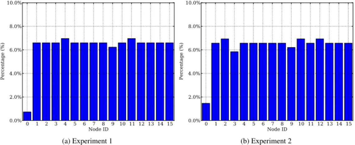
(18) 15. CRQ DTQ. Success Empty. 200. 15. CRQ DTQ. Success Empty. 150 10 Packet count. Packet count Queue length. Queue length. 150 10. 100 5. 100 5. 50. 00. Success: 99.27% Empty: 0.73% Error: 0.0%. 20. 40. 60. 80. 100 120 140 160 180 2000 Slot #. (a) Experiment 1. 200. 50. 00. Success: 98.54% Empty: 1.46% Error: 0.0%. 20. 40. 60. 80. 100 120 140 160 180 2000 Slot #. (b) Experiment 2. Figure 7: Queue Lengths and Packet Count Evolution for Two Different Experiments, (a) and (b), with 15 nodes. Note that in both experiments there are no packet collisions or error packets.. caused by two effects. First, due to the fact that the initial data subperiods are empty because the DTQ is empty, as nodes are waiting in the CRQ to resolve their ARP collisions. Second, nodes may loose synchronization with the CRQ and DTQ values due to a corrupt FBP caused by the effects of multipath propagation or external interference. Under such circumstances, nodes are forced to reset their respective pointers to the DTQ and CRQ to avoid interfering with other nodes. Thus, the data subperiod assigned to these nodes will be empty. However, it is important to remark that such event does not affect the remaining nodes because they will update their pointers accordingly upon the reception of the FBP. Figure 8 shows the histogram for the same two experiments presented in Figure 7. In this case, the horizontal axis represents the unique identifier of each node that takes part of the experiment, whereas the vertical axis is the percentage of data subperiods assigned to each of these nodes. It is important to remark that the bin with Node ID zero is the probability that a data subperiod is empty due to the reasons explained before. The main aspect to observe in Figure 8 is how all nodes receive a fair share of the network resources despite the fact that there is no scheduler that determines which node can transmit at each frame. That is, the network is able to autonomously build a schedule using the BTSA and the information obtained from resolving the collisions in the access subperiod. In particular, each node in the network receives one out of each n data subperiods, with n being the number of nodes that are part of the network. The small differences that can be appreciated among certain nodes (below 1.0%) are due to the fact that a single experiment only lasts for approximately 255 frames and, at that point, some nodes may have had the chance to transmit an additional data packet whereas other nodes are still waiting on the DTQ to transmit their respective data packet. 5.2. Average performance In this subsection, the experiment setup to evaluate the average performance of LPDQ is the same as in the previous section. Nodes synchronize using the low-power listening mechanism and transmit data packets to the coordinator. Each experiment is comprised of 2 seconds for network synchronization and 3 seconds for data transmission, which translates into approximately 17.
(19) 10.0%. 8.0%. 8.0% Percentage (%). Percentage (%). 10.0%. 6.0% 4.0%. 6.0% 4.0%. 2.0%. 2.0%. 0.0% 0 1 2 3 4 5 6 7 8 9 10 11 12 13 14 15 Node ID. 0.0% 0 1 2 3 4 5 6 7 8 9 10 11 12 13 14 15 Node ID. (a) Experiment 1. (b) Experiment 2. Figure 8: Data transmission histogram for two different experiments, (a) and (b), with 15 nodes. Note that Node ID zero represents the empty probability.. 255 frames being elapsed. However, here we conduct experiments with a different number of nodes (from 5 to 25 nodes, in steps of 5 nodes) to evaluate the data transmission mechanism of LPDQ. In addition, in this case, we repeat each experiment 100 times and compute the average and standard deviation of the computed values to observe how LPDQ behaves on the average depending on the number of nodes in each experiment. As presented earlier, two key performance indicators of LPDQ are the evolution of the lengths of the CRQ and the DTQ depending on the number of nodes that are in the network. Figure 9a shows the average evolution of the length of the CRQ for the different number of nodes in each experiment. Each point in the line is the average of 100 experiments and the shadowed surface above and below the average curve represents the standard deviation of each experiment. In the beginning of the experiment, the length of the CRQ grows rapidly due to the collisions occurring in the ARP slots when all the devices attempt to get access to the channel. However, the BTSA algorithm splits collisions into subgroups and allows to resolve them in subsequent frames. Once a collision is resolved, the successful nodes enter the DTQ at the last position (in any arbitrary order, for example using the chronology of the access slots), thus ensuring that no collisions exist during the transmission of data packets. Finally, after a certain number of frames, the length of the CRQ converges to zero. Since only one node can leave the DTQ at a given frame, once the network reaches steady state operation, the CRQ is always empty in average. However, as described on the previous section, small deviations exist due to the fact that the collision resolution process is non-deterministic. It is worth recalling that the BTSA is blocking; thus, nodes that have already transmitted a data packet have to wait until the CRQ is empty to be able to enter the network again. This behavior explains the sudden increase in the length of the CRQ after it starts decreasing, e.g., around frame 15 for the experiment with 25 nodes. At that point, all the nodes that have already transmitted a data packet will try to access the system again because the CRQ is empty, causing another batch of ARP collisions. However, the BTSA resolves these collisions again and the length of the CRQ converges again to zero. Note that the number of contending nodes in this second batch of collisions is lower than at the beginning because there are nodes which are still in the DTQ 18.
(20) 6 5. 3 2. 15 10 5. 1 00. 5 Nodes 10 Nodes 15 Nodes 20 Nodes 25 Nodes. 20 DTQ length. 4 CRQ length. 25. 5 Nodes 10 Nodes 15 Nodes 20 Nodes 25 Nodes. 10. 20. Frame # (a). 30. 40. 50. 00. 20. 40. 60. 80. 100 120 140 160 180 200 Frame # (b). Figure 9: Evolution of the average length of the CRQ (a) and the DTQ (b) depending on the number of nodes in the network in each experiment.. waiting for their turn to transmit. In this case, the collision resolution algorithm and the data transmission process are executed simultaneously, leading to an improved network performance. Figure 9b shows the evolution of the average length of the DTQ for the different number of nodes in each experiment. Again, the horizontal axis represents the time evolution in terms of the frame number, where each point is the average of 100 experiments and the shadowed surface above and below the average curve represents the standard deviation of each experiment, and the vertical axis represents the average length of the DTQ. It is possible to observe how the length of the DTQ rapidly converges to n − 1 and the standard deviation is bounded. This is due to the fact that at each frame only one node can leave the DTQ. It is also important to remark that the time it takes for the length of the DTQ to converge is bounded. In the worst case scenario, this time is determined by the BTSA, which depends on the value of n and m. LPDQ yields a performance close to the optimal that can be achieved at the MAC layer thanks to the use of the distributed queues CRQ and DTQ, and the use of the BTSA. In addition, since collisions are confined to the ARPs slots, which are very small compared to the data subperiod, the energy required to solve collisions is smaller. Moreover, the concurrent execution of the collision resolution algorithm and the transmission of data offers a performance advantage with other MAC protocols using data packets for contention. Finally, Figure 10 shows the average of the outcome of data packet transmissions with LPDQ. This figure shows the percentage of success, empty and error packets depending on the number of nodes present in each experiment. Each point is the average of 100 experiments and the error bars represent the standard deviation. As it is possible to observe, LPDQ achieves a MAC performance close to 99% with a typical standard deviation smaller than 5% regardless of the number of nodes. This behavior is caused by the fact that there are no data-packet collisions. Instead, the collisions are confined to the ARP slots and, based on its outcome, nodes are organized into the distributed queues CRQ and DTQ using the BTSA. However, there is a small probability that some data subperiods are empty, e.g., 2% for the experiment with 20 nodes. As presented earlier, this behavior may be caused by the effects of external interference or multi-path propagation, which may cause a FBP packet to not be successfully received by a node. This leads to the reset 19.
(21) of the DTQ and CRQ pointers, which forces that particular node to re-enter the system. In that case, the data subperiod assigned to the node will be empty because no other node will be able to transmit its data packet. However, as described earlier, such event does not affect the remaining nodes in terms of throughput, latency, fairness or energy consumption, because they will update their pointers accordingly upon the reception of the FBP. In conclusion, LPDQ offers a clear performance advantage over FSA or any other random access packet based on contention with data packets. Even in the optimal case, e.g., when the number of slots per frame is equal to the number of nodes in the network, FSA yields a MAC performance of only 36.8%. This implies that, with FSA, approximately only 4 out of 10 packets transmitted by the nodes will be successfully received by the coordinator. This increases the amount of time required to collect information from all the nodes of the network and it also increases the average energy consumption of nodes. Note that every packet retransmission leads to additional energy charge being extracted from the battery. In addition, it is important to remark that optimum performance of FSA can be achieved when n = m, which implies a priori knowledge of the network. However, LPDQ operates independently of the number of devices in the network. Finally, it is worth highlighting another interesting property of LPDQ; even without a network schedule that determines how resources are assigned to nodes, the MAC protocol is fair. As nodes join the DTQ in order and only one node can leave the DTQ at a time, all nodes in the network receive the same amount of network resources, e.g., transmission opportunities.. 100. LPDQ Success FSA Success LPDQ Col+Err FSA Col+Err. Percentage (%). 80 60 40 20 0. 5. 10. 15 Node count. 20. 25. Figure 10: Average data packet transmission with FSA and LPDQ. Note that the LPDQ Col+Err bar does not appear because there are no packet collisions or error packets in the experiments.. 6. Conclusions This paper has introduced LPDQ as a novel efficient, fair, and low-power MAC protocol specifically suited for wireless data collection scenarios with a large number of mobile nodes that generate bursty traffic. Today, such scenarios are typically addressed by MAC protocols based on FSA, which has a maximum efficiency of 36.8% due to the effects of contention. Moreover, such efficiency can only be achieved when the number of slots per frame is equal to the 20.
(22) number of nodes in the network, which is unknown a priori. On the contrary, LPDQ is able to dynamically build and dynamically update a network schedule that enables all nodes to transmit free-of-collisions data packets, thus achieving efficiencies close to 99%. In addition, LPDQ performance is independent of the number of nodes in the network and fair in the sense that all nodes receive a similar amount of network resources. The paper has presented the design principles, operation fundamentals, implementation details of LPDQ and an experimental evaluation using real hardware. The implementation and the results presented in this paper demonstrate the suitability of the technology for low-power commercial radio transceivers and outline it as a clear candidate for upcoming IoT standards targeted at data collection scenarios with an unpredictable number of connected devices. Acknowledgments This work has been partially supported by the Research Projects CALIPSO (FP7-288879), RELYONIT (FP7-317826), SWAP (FP7-251557), CO2GREEN (TEC2010-20823), GREEN-T (TSI-020400-2011-16), NEWCOM# (FP7-318306), GEOCOM (TEC2011-27723-C02-01), and by the Catalan Government under grant 2009SGR1046. Pere Tuset is funded by an Internet Interdisciplinary Institute (IN3) grant. Xavier Vilajosana is funded by the Spanish Ministry of Education under Fullbright-BE grant (INF-2010-0319). References [1] L. Atzori, A. Iera, G. Morabito, The Internet of Things: A survey, Computer Networks 54 (2010) 2787 – 2805. [2] M. Palattella, N. Accettura, X. Vilajosana, T. Watteyne, L. Grieco, G. Boggia, M. Dohler, Standardized Protocol Stack for the Internet of (Important) Things, Communications Surveys & Tutorials, IEEE 15 (2013) 1389–1406. [3] M. Zorzi, A. Gluhak, S. Lange, A. Bassi, From today’s intranet of things to a future internet of things: a wirelessand mobility-related view, Wireless Communications, IEEE 17 (2010) 44–51. [4] N. Fourty, A. van den Bossche, T. Val, An advanced study of energy consumption in an IEEE 802.15.4 based network: Everything but the truth on 802.15.4 node lifetime, Computer Communications 35 (2012) 1759–1767. [5] W. L. Tan, W. C. Lau, O. Yue, Performance analysis of an adaptive, energy-efficient MAC protocol for wireless sensor networks, Journal of Parallel and Distributed Computing 72 (2012) 504 – 514. [6] A. Bachir, M. Dohler, T. Watteyne, K. Leung, Mac essentials for wireless sensor networks, Communications Surveys Tutorials, IEEE 12 (2010) 222–248. [7] IEEE Standard for Local and metropolitan area networks–Part 15.4: Low-Rate Wireless Personal Area Networks (LR-WPANs) Amendment 1: MAC sublayer, IEEE Std 802.15.4e-2012 (Amendment to IEEE Std 802.15.4-2011) (2012) 1–225. [8] L. Doherty, W. Lindsay, J. Simon, Channel-specific wireless sensor network path data, in: Computer Communications and Networks (ICCCN), 16th International Conference on, pp. 89–94. [9] T. Watteyne, X. Vilajosana, B. Kerkez, F. Chraim, K. Weekly, Q. Wang, S. Glaser, K. Pister, OpenWSN: a standards-based low-power wireless development environment, Transactions on Emerging Telecommunications Technologies 23 (2012) 480–493. [10] X. Vilajosana, Q. Wang, F. Chraim, T. Watteyne, T. Chang, K. Pister, A Realistic Energy Consumption Model for TSCH Networks, Sensors Journal, IEEE (2013). [11] C. Cano, B. Bellalta, A. Sfairopoulou, M. Oliver, Low energy operation in WSNs: A survey of preamble sampling MAC protocols, Computer Networks 55 (2011) 3351–3363. [12] J. Yick, B. Mukherjee, D. Ghosal, Wireless sensor network survey, Computer Networks 52 (2008) 2292–2330. [13] V. Namboodiri, M. DeSilva, K. Deegala, S. Ramamoorthy, An extensive study of slotted Aloha-based RFID anticollision protocols, Computer Communications 35 (2012) 1955 – 1966. [14] ISO 18000-1:2008, Radio frequency identification for item management – Part 1: Reference architecture and definition of parameters to be standardized, ISO, Geneva, Switzerland, 2008. [15] ISO 18000-7:2009, Radio frequency identification for item management – Part 7: Parameters for active air interface communications at 433 MHz, ISO, Geneva, Switzerland, 2009.. 21.
(23) [16] W.-J. Yoon, S.-H. Chung, S.-J. Lee, Implementation and performance evaluation of an active RFID system for fast tag collection, Computer Communications 31 (2008) 4107 – 4116. [17] M.-K. Yeh, J.-R. Jiang, S.-T. Huang, Adaptive splitting and pre-signaling for RFID tag anti-collision, Computer Communications 32 (2009) 1862–1870. [18] B. Lars, S. Bertil, An Energy and Application Scenario Aware Active RFID Protocol, EURASIP Journal on Wireless Communications and Networking 2010 (2011). [19] K.-W. Chin, D. Klair, E2MAC: An energy efficient MAC for RFID-enhanced wireless sensor networks, Pervasive and Mobile Computing 7 (2011) 241–255. [20] C. Qian, Y. Liu, R. H. Ngan, L. M. Ni, ASAP: Scalable Collision Arbitration for Large RFID Systems, Parallel and Distributed Systems, IEEE Transactions on 24 (2013) 1277–1288. [21] H. Wu, Y. Zeng, J. Feng, Y. Gu, Binary Tree Slotted ALOHA for Passive RFID Tag Anticollision, Parallel and Distributed Systems, IEEE Transactions on 24 (2013) 19–31. [22] A. J. E. M. Janssen, M. J. de Jong, Analysis of contention tree algorithms, Information Theory, IEEE Transactions on 46 (2000) 2163–2172. [23] W. Xu, G. Campbell, A near perfect stable random access protocol for a broadcast channel, in: Communications (ICC), 1992 IEEE International Conference on, pp. 370–374. [24] L. Alonso, R. Agusti, O. Sallent, A near-optimum MAC protocol based on the distributed queueing random access protocol (DQRAP) for a CDMA mobile communication system, Selected Areas in Communications, IEEE Journal on 18 (2000) 1701–1718. [25] J. Alonso-Zarate, C. Verikoukis, E. Kartsakli, A. Cateura, L. Alonso, A near-optimum cross-layered distributed queuing protocol for wireless LAN, Wireless Communications, IEEE 15 (2008) 48–55. [26] E. Kartsakli, A. Cateura, L. Alonso, J. Alonso-Zarate, C. Verikoukis, Cross-layer enhancement for WLAN systems with heterogeneous traffic based on DQCA, Communications Magazine, IEEE 46 (2008) 60–66. [27] J. Alonso-Zarate, E. Kartsakli, L. Alonso, C. Verikoukis, Performance analysis of a cluster-based MAC protocol for wireless ad hoc networks, EURASIP Journal on Wireless Communications and Networking 2010 (2010). [28] B. Otal, L. Alonso, C. Verikoukis, Highly reliable energy-saving MAC for wireless body sensor networks in healthcare systems, Selected Areas in Communications, IEEE Journal on 27 (2009) 553–565. [29] T. Winter, P. Thubert, A. Brandt, J. Hui, R. Kelsey, P. Levis, K. Pister, R. Struik, J. Vasseur, R. Alexander, RPL: IPv6 Routing Protocol for Low-Power and Lossy Networks, RFC 6550 (Proposed Standard), 2012. [30] T. Instruments, CC430 Datasheet: MSP430 SoC With RF Core, 2013. [31] IEEE Standard for Local and metropolitan area networks– Part 15.4: Low-Rate Wireless Personal Area Networks (LR-WPANs) Amendment 2: Active Radio Frequency Identification (RFID) System Physical Layer (PHY), IEEE Std 802.15.4f-2012 (Amendment to IEEE Std 802.15.4-2011) (2012) 1–72. [32] IEEE Standard for Local and metropolitan area networks–Part 15.4: Low-Rate Wireless Personal Area Networks (LR-WPANs), IEEE Std 802.15.4-2011 (Revision of IEEE Std 802.15.4-2006) (2011) 1–314. [33] P. Tuset-Peiro, A. Angles-Vazquez, J. Lopez-Vicario, X. Vilajosana-Guillen, On the suitability of the 433 MHz band for M2M low-power wireless communications: propagation aspects, Transactions on Emerging Telecommunications Technologies (2013) n/a–n/a. [34] W. Xu, G. Campbell, A distributed queueing random access protocol for a broadcast channel, SIGCOMM Comput. Commun. Rev. 23 (1993) 270–278. [35] D. Stanislowski, X. Vilajosana, Q. Wang, T. Watteyne, K. Pister, Adaptive Synchronization in IEEE802.15.4e Networks, Industrial Informatics, IEEE Transactions on (2013) 1. [36] K. Whitehouse, A. Woo, F. Jiang, J. Polastre, D. Culler, Exploiting the capture effect for collision detection and recovery, in: Embedded Networked Sensors, 2005. EmNetS-II. The Second IEEE Workshop on, pp. 45–52. [37] T. Watteyne, S. Lanzisera, A. Mehta, K. Pister, Mitigating multipath fading through channel hopping in wireless sensor networks, in: Communications (ICC), 2010 IEEE International Conference on, pp. 1–5. [38] Zornitza Genova Prodanoff, Optimal frame size analysis for framed slotted ALOHA based RFID networks, Computer Communications 33 (2010) 648–653.. 22.
(24)
Figure
+7
Documento similar
