Mobile ad hoc routing protocols survey for the design of VANET applications
7
0
0
Texto completo
(2) Mobile Ad-Hoc Routing Protocols Survey for the Design of VANET Applications Roger Michoud. Ana Marı́a Orozco. Gonzalo Llano. Swiss Federal Institute of Technology Lausanne EPFL, Switzerland Email: roger.michoud@epfl.ch. Universidad Icesi, Cali, Colombia i2T Research Group Email: amorozco@icesi.edu.co. Universidad Icesi, Cali, Colombia i2T Research Group Email: gllano@icesi.edu.co. Abstract—Vehicular communications are considered as a key factor to improve road safety and enhance urban mobility. The design and deployment of Vehicular Ad hoc Networks (VANETs) involve several decision criterias that lead the research into new challenging tasks to be solved. Routing mechanism is a fundamental component for the success of any vehicular application; the particular features of VANETs - a highly dynamic topology, links frequently disrupted and a fragmented network - require an efficient, robust and scalable routing strategy for each application. In this paper, we present a survey of routing protocols and we also provide a simulation testbed that will be used to assess the performance of the selected protocols. Index Terms—Ad hoc routing protocols, VANET, Intelligent Transport System, Vehicular applications.. an On-Board Unit (OBU). The function of the OBU is to exchange information with other vehicles or access points in the road, called Road Side Units (RSU). Data associated with traffic and environmental conditions (i.e. pollution, temperature, vibration, pressure, movement, among others) is collected by the Vehicular Network Sensor (VNS) and then the information is processed by the applications in order to generate and send messages over the wireless network [1]. B. Characteristics. Most of the research on VANETs until now is based on the implementation and survey of the two first layers of the OSI model (Physical and Data Link layers). It is now time to focus the efforts on the next challenge: Designing the network layer. A key component of the network layer is the routing protocols. We wanted this paper to be a grounded analysis of the different types of existing protocols: how they work, for which scenarios are they more efficient and how to chose them wisely regarding the vehicular application requisites. The routing protocols for VANETs fall into three (3) categories: Broadcast, Geocast and Unicast routing. Each of them carries its proper challenges. We will mostly debate the Geocast and Unicast cases because they are the categories we need for our applications. Our goal is to provide a study of these routing protocols in order to select the most suitable ones for VANET application requirements. The rest of this paper is organized in the following sections: Section II describes the general characteristics of VANETs. In Section III we classify V2X applications and we also describe the simulation tools and techniques for vehicular communications. Section IV describes the design of VANETs network layer and finally Section V presents our conclusions.. There are two (2) types of communication in the vehicular environment: vehicle-to-vehicle communication (V2V), where the nodes directly exchange messages; and vehicleto-infrastructure communications (V2I) where the information exchange takes place between a car and a device on the road such as tolls and Internet access points. VANET characteristics are listed bellow: Variant topology: Due to high speed and continuous movement of vehicles the network topology is highly dynamic. Non-infrastructure network : V2V communications are based in the ad hoc network architecture, there is no central authority node that manages the others. All the nodes must self-organize and self-manage the connections and transmissions. Frequently disconnected network: The dynamic network topology causes frequent node disconnections; the link between the vehicles can be easily lost causing packet loss in transmissions. Unlimited battery power and storage: The nodes have no restriction of power consumption, since the vehicles battery provides sufficient amount for all the operations. Radio-communication aspects: Radio-communication in VANETs is complex due to several factors: frequent interruptions of the radio-link, unfavorable conditions for signal propagation (attenuation and reflection) and interference with other radiofrequency.. II. V EHICULAR A D - HOC N ETWORKS. III. A PPLICATIONS AND SIMULATION TOOLS. I. I NTRODUCTION. A. Definition and components. A. Vehicular applications. Vehicular Ad Hoc Networks are considered as an extension of Mobile Ad Hoc Networks (MANETs); in a VANET each vehicle is a node of the wireless network, equipped with. VANETs represent an opportunity to develop applications that improve the transportation sector and the traffic conditions through collaborative systems based on V2X communications.. 978-1-4673-4362-6/12/$31.00 c 2012 IEEE.
(3) The purpose of Intelligent Transport systems (ITS) and its applications is the improvement of road safety and urban mobility through the management and monitoring of traffic flow with real time notifications. According to the functionality, the applications are classified in three (3) primary categories: Road safety, traffic efficiency and commercial services (Infotainment) [2]. Table I shows the applications classification and their impact. B. VANET simulation VANET simulation is a valuable tool to analyze and evaluate the feasibility, benefits and requirements of ITS applications. The degree of realism and reliability of the simulation results mainly depend of two (2) aspects: the integration of a network simulator with a representative mobility model and the election of accurate metrics for results evaluation. The purpose of coupling a network simulator with a traffic simulator is to create a realistic scenario, where the mobile nodes in the topology network could be influenced by the mobility patterns in a real world map. The network simulator software is used to model and evaluate the performance of the components in the vehicular communication systems such as protocols, standards, algorithms, configurations, channel conditions, among others. Moreover, the function of the traffic simulator is to generate a mobility model in a real topographic scenario, using parameters such as vehicles speed, traffic density and road topology. Mobility patterns determine the behavior of traffic flow and provide the location, trajectory, etc., of the nodes in the topology map[3]. One of the key features of the simulators of VANETs is the coupling of network and mobility modules. We decided to choose Vehicles in Network Simulation (Veins) simulator among other simulation frameworks (TraNS, iTetris, VGSim, VSimRTI, NCTUns and GrooveNet) [4] in order to test our applications and protocols within geographic data scenarios because Veins is a V2X communication simulation framework composed of an event-based network simulator, OMNeT++, and a road traffic simulation software, SUMO (Simulation of Urban Mobility). Both models are bi-directionally coupled and the simulations run in parallel, connected by a Traffic Control Interface (TraCI). This allows the road traffic to have a direct impact on the network performance and vice versa. IV. D ESIGN OF VANET S NETWORK LAYER The VANET network layer is a very challenging field to investigate. VANET characteristics make the normal design of the OSI 3rd layer in the MANET framework not completely suitable for this special category. The routing protocols involved in the information dissemination mechanisms have to deal with these constraints. In this section, we will first analyze the network attributes of the different applications we want to implement. Secondly, we will explain what are the different categories of VANET routing protocols and show the decision process that led to the chosen protocols. Finally we will discuss in the conclusion the utility of these protocols for the other applications of the VANET framework.. A. Application characteristics and network attributes Our main goal is to implement five (5) applications: •. •. •. •. •. Cooperative Collision Warning (CCW): vehicles collect traffic information (speed, direction) to warn the driver of potential collision. Cooperative Violation Warning (CVW): the RSU collects driving information to warn the vehicles of potential signal violation (speed, location, etc.). V2V Post Crash Notification (PCN): Vehicles involved in a crash broadcast warning messages to approaching vehicles. Congested Road Notification (CRN): A vehicle detects road congestion and broadcasts the information to other vehicles in the area. Traffic Probe (TP): A probe vehicle monitors traffic information and transmits it to the next RSU. Then the RSU transmits it to a traffic management center.. In this section, we will describe for each of them the different characteristics and network assumptions. This process will help us to select the best suited routing algorithms. Before diving into the description of the applications, it is important to have a quick look at the criterias of classification [5]. For the application characteristics: • •. • •. Participants: It basically specifies if it is a V2V or a V2I application. Region of interest: it describes the geographical range of the application (long (> 1km), medium (∼ 1km) and short (< 500m)). Trigger condition: It states how the application is triggered (periodic, event-driven, or user-initiated). Recipient pattern: This criteria is describing the message receivers pattern. In other words, it says to whom the messages emitted have to be transmitted (one-to-many, one-to-a-zone, one-to-one, many-to-one).. For the Network attributes: •. • •. •. Channel frequency: describes the operational channel. We can choose between three (3) standards: DSRC-Control Channel (CCH), a single channel used for safety application, DSRC-Service Channels (SCHs), six (6) channels used for commercial applications and Wi-Fi. Infrastructure: specifies if we need a Road Side Unit (RSU) or not. Message Time-to-Live (TTL): states the way we will forward messages. This criteria is highly correlated with the region of interest one. Here we have two (2) categories : single-hop routing and multi-hop routing. We will later explain the difference between this two modes of routing packets and what kind of impact they have on the design of the network layer. Message packet format: specifies the network packets format used to encapsulate application messages. Here we can choose between two standards, the famous IP protocol or the WAVE Short Message Protocol (WSMP) designed within the WAVE standard framework. We will.
(4) TABLE I V EHICULAR APPLICATIONS CLASSIFICATION Category. Sub-classification Collision avoidance. Safety Applications. Road sign notification Incident management. Traffic Management Efficiency Applications Traffic Monitoring Contextual Information Infotainment Applications Entertainment. •. •. Vehicular Application Cooperative collision warning Safe-distance notification Hazardous intersection message Curve speed warning Cooperative violation warning Emergency vehicle notification Post crash notification Intelligent traffic flow control Roadways planning Congested road notification Road conditions sensing Vehicles and fleet tracking Commercial services announcement Parking assistance Media-content download Distributed games. favor IP protocol when the application needs to be connected to outside of the VANET network. Routing protocols: This network attribute is highly related to the Recipient pattern criteria. So we have basically four (4) different categories; broadcast (one-to-many) and geocast (one-to-a-zone) for safety applications and unicast (one-to-one) and aggregation (many-to-one) which are more suitable for commercial applications. Network protocol initiation mode: it reflects the Trigger condition criteria but at the network level. There are three (3) different modes; Beacon mode (periodic), event-triggered mode (event driven) and user-initiatedon-demand mode (user-initiated).. On Table II we can see the application characteristics and on Table III the network attributes of the applications. CCW and CVW both share a lot of common features. But within the group of all applications, they are very specific and different from the others. There are the only safety applications that have single-hop TTL and broadcast routing protocols. The main difference between them are that CVW needs infrastructure (RSU) and CCW doesn’t. This can also be seen in the application participants criteria, CVW is V2I and CCW is V2V. The interesting characteristics for the design of the network layer are that they are single-hop and broadcast. This means that we don’t need any ad hoc multi-hop routing protocol. We just forward the message to all the nodes that are in the range of transmission. An other property is that they are both triggered by beacon, so it means we are on a periodic message emission pattern. With the other applications, it becomes much more interesting in the routing protocols point of view. The main differences are that they are multi-hop, geocast / unicast and event-triggerd. This have huge repercussions on the network architecture. Now we need to implement routing algorithms that can handle the challenging nature of VANETs.. Deployment Impact Reduce fatalities and risks of accidents Improve driving safety Fast and efficient response. Optimization of urban mobility Reduce time and fuel comsuption. Location-based services (travel guides, updated routes and maps) and Internet. B. VANET Routing Protocols Due to the diversity of applications in the VANET framework, we have to design specific protocols for the tree main categories (Broadcast, Geocast and Unicast) [6] . Each category has its own challenges: Broadcast protocols are hard to design because we have to transmit the information to the whole network. Broadcasting usually generates a large amount of redundancy, contention and collision. These issues are know as the Broadcast Storm problem. Geocast routing challenges are to forward the packets only to a selected region. The main goal is to solve the reliability issue due to the frequently variable topology. Unicast routing protocols is most likely to be the most complex category, because we have to find a stable route (that probably will change during the time of transmission) between the source and the receiver. The main challenge is to find a route and have recovery mechanisms when some path of the route is down. In the following, we will analyze the two most used categories of protocols (because most of the applications use them): Geocast routing and Unicast routing protocols. C. Geocast routing protocols There are two main protocols for Geocast routing: Distributed Robust Geocast (DRG) and Inter-Vehicle Geocast (IVG). They both provide a way to achieve geocast in an environment with temporary network fragmentation. We will discuss the important concepts of each of them based on [6]. DRG works under this assumption: If a node is located within the targeted geographic region, it will receive the packets. Otherwise, it will just drop it. In order to implement this protocol, we introduce two principles: the zone of relevance (ZOR) and the zone of forwarding (ZOF). The ZOR is the proper geographic area that we want to cover. The ZOF is used in order to be sure that the messages will reach every nodes in.
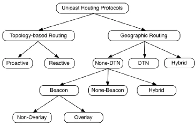
(5) TABLE II A PPLICATIONS CHARACTERISTICS Name Cooperative Collision Warning Cooperative Violation Warning Post Crash Notification Congested Road Notification Traffic Probe. Acronym CCW CVW PCN CRN TP. Category Safety Safety Safety Convenience Convenience. Participants V2V V2I V2V V2V V2I. Region of interest Short Short Medium Long Long. Trigger Periodic Periodic Event Event Event. Recipient pattern One-to-many One-to-many One-to-a-zone One-to-a-zone One-to-one. TABLE III N ETWORK ATTRIBUTES Acronym CCW CVW PCN CRN TP. Channel frequency DSRC-CCH DSRC-CCH DSRC-CCH DSR-SCH DSR-SCH. Infrastructure No Yes No No Yes. TTL Single-hop Single-hop Multi-hop Multi-hop Multi-hop. the ZOR. All the vehicles present in the ZOF will forward the messages to vehicles present in ZOR. Usually, ZOF surrounds ZOR. This mechanism is implemented in order to solve the frequently changeable topology issue. The source node will periodically retransmits the messages to the ZOF in order to solve the network fragmentation problem. IVG is designed in a slightly different way. The geographic region is called the risk area. All the nodes present within this area are part of a multicast group. In order to define this group, we will use features as location, speed and driving direction. Like DRG, the messages are sent periodically to solve the temporary network fragmentation problem. However, the mechanism is a bit more complex because IVG uses the deferring time technique: A vehicle situated further waits less time before re-broadcast. For PCN and CRN applications, we will implement both of them to compare their efficiency in different scenarios. D. Unicast routing protocols For the implementation of the TP application, we have to consider the unicast routing protocols. We can divide them in different categories [7]. This section is about explaining the main mechanisms of these groups of protocols in order to select the most suitable ones to simulate. We will also walk through the pros and cons of each category. First, we can classify all the unicast routing protocols in two (2) main classes: Topology-based routing and Geographic routing. The first one is considered as the traditional way of routing packets in MANETs. The second one is more specific to the VANET nature. We will now go through both of them. We can see on Figure 1 the anatomy of unicast routing protocols. 1) Topology-based routing protocols: The main characteristic of the Topology-based routing protocols is that they only use the links information. It means that we don’t really care where is the node, but we just base the routing tables on which nodes are connected together. This is a very efficient method for MANETs, but let’s see how it performs for VANETs. We can separate them in proactive protocols and reactive protocols. In the proactive protocols, the nodes are periodically. Packet format WSMP WSMP WSMP WSMP WSMP. Routing protocol Broadcast Broadcast Geocast Geocast Unicast. Trigger Beacon Beacon Event-triggered Event-triggered Event-triggered. Unicast Routing Protocols. Topology-based Routing. Proactive. Geographic Routing. Reactive. None-DTN. Beacon. None-Beacon. Non-Overlay. Fig. 1.. DTN. Hybrid. Hybrid. Overlay. Unicast routing protocols anatomy. sending route discovery packets in order to know the structure of the actual network. On the other hand, the reactive protocols are working “on demand”. It is only when a node needs to transfer a packet that it will send the route discovery packet. In the proactive routing, every node has a routing table that it updates on a periodic manner. It means at every moment t, each node knows the next hop to all the destinations. The strength of these protocols is that they provide low-latency for real-time applications. When node S (Source) needs to send a packet to node D (Destination), it just have to check in the table and send it. This is why it is very efficient. But on the flip side, it means that the network is periodically flooded with route discovery packets. Another issue with this kind of routing is that there are some paths that are almost never used but we still have to maintain the routes. It implies that we generate a lot of unnecessary traffic and therefore we lose a lot of efficiency, specially with the high mobility environment of vehicular networks. Reactive routing presents a lot of interesting features. In opposition to proactive routing, the discovery mechanism is triggered only when a node wants to communicate and the route is maintained only during the transmission of packets. This permits to reduce flooding of the network and also avoid.
(6) the unused path problem. But as it is always a tradeoff, what we gain in network traffic, we lose in time of transmission. Let’s get back to our example where node S wants to send a packet to node D. This time node S has to start with the discovery phase where he will find a route from S to D. When it finds the route, it then can send the packet. So the time to transmit information is longer. This mechanism suits better the nature of VANETs: because we are in a highly mobile environment the route are changing very fast. So it is better to find a route at the time of transmitting, because we are sure that this route is still up. The most known reactive protocols are Ad hoc On demand Distance Vector (AODV) and Dynamic Source Routing (DSR). Topology-based routing is definitely not the best solution for VANETs. These protocols were not designed to cope with nodes that are moving so fast. Lochert et al [8] performed some evaluation studies on these protocols and the results are that they all have the same problem: performance degrades as the network density increases. The main issue is the route discovery mechanism. Because it is based only on links information, the routes are always changing and the nodes have to perform several route discovery phases to succeed in transmitting packets to another node. This generates a surplus of traffic that congestions the network. 2) Geographic routing protocols: The position-based routing algorithms forwarding mechanism is based on the location of the destination node. This means that all nodes are aware of their proper location. This is why geographic routing requires a GPS (Geographic Positioning System). Every node is sending a beacon to figure out which other nodes are in the range of communication. They become the one-hop neighbor nodes. In order to prevent collision, the beacons are sent with a random Packet Delay Variation (PDV) to avoid collision of the beacon packets. The main strength of this category of protocols is that we don’t need to establish a route to forward a packet, this is why it is best suited to VANETs. Let’s revisit the example of node S wanting to transmit to node D. Node S will forward his packet to the one-hop neighbor node that is the closest of node D and so on until reaching it. This strategy has a flaw but we will discuss it and the way we solve it later. Geographic routing protocols contain three (3) main categories: None Delay Tolerant Network (None-DTN), Delay Tolerant Network (DTN) and Hybrid. The None-DTN are designed for highly dense network because if there is no route between two nodes (disconectivity) the packet is lost. DTN permits to keep these packets in the node until they can deliver the packet to a closest node. This is why there are more designed for sparse network. Hybrid systems combine the two modes. They are designed to cope with partially connected network. Because we are in urban environment, the None-DTN category is the best choice. The first three (3) subdivision of None-DTN are Beacon, None-Beacon and Hybrid. We will only focus on the Beacon category because it contains the most diversified and mature protocols. Within this category we can classify the protocols in two (2) classes: Non-Overlay and Overlay routing protocols.. None-DTN principal mechanism is to forward the packets to the next hop closest to the destination node. This greedy approach has a flaw, it can happen that no other node is closer to the destination than the node itself but it cannot reach the destination. We call this particular node the local maximum, because that’s the furthest local node that the packet can travel to. If all the protocols in this category are based on this approach, each of them handles the local maximum issue in its proper way. The principle of Beacon protocols is that each node is periodically sending its location information to all of the nodes that are in the range of communication. Like this each node is aware of the position of its neighbors. With the None-Overlay routing algorithms, every node has the same importance. However, with the Overlay routing algorithms, some nodes are more important for the routing protocol. They are called the overlaid nodes. It is very similar to the concept of peers and superpeers in a Peer-to-Peer network. The overlaid nodes make the biggest part of the processing job. In the context of a vehicular network, we can easily see that the most important decisions are taken at the crossroads. Hence, the nodes that are located on this junctions, are the chosen ones. The routing along the roads is easier because it is always in the same direction. E. Chosen protocols: DRG, IVG, GPSR+AGF and CAR For the Geocast protocols, we chose to simulate the DRG and IVG protocols. The other options are variations of these protocols, so it will be easy to adapt our simulation module in order to extend it to these versions. For the Unicast protocols, we decided to choose two different protocols in the Geographic, None-DTN, Beacon category. The reasons are the ones put in bold in the section IV-D. In the None-Overlay routing category, we decided to choose GPSR+AGF. Greedy Perimeter Stateless Routing (GPRS) is usually used as a reference protocol when it comes to analyze the performance of another routing algorithm. We decided to implement a variation of this protocol: GPSR+ Advance Greedy Forwarding (AGF). On the other hand, for the Overlay routing category, we chose the Connectivity-Aware Routing (CAR) protocol. It basically adapts the variation of the famous topology-based routing protocol (AODV+PGB) in order to consider the geographic location of the nodes. In the following paragraphs we will give some details of the functioning of these two algorithms. The first component of the GPSR+AGF is the GPSR. In GPSR, a node will forward the packets to the one-hop neighbor closest to the destination. We call this mode greedy mode. What distinguishes this protocol from the others is the way it handles the local maximum issue. The recovery phase uses a perimeter mode implementing the right-hand rule. The rule is: ”When a node x first enters into the recovery mode, its next forwarding hop y is the node that is sequentially counterclockwise to the virtual edge formed by x and destination D” [7]. In other words, we start with the xD virtual edge. We take the first next edge (counterclockwise). The next node of the route is the destination of this new edge (here it would be y, from.
(7) the edge xy). Then we repeat the operation with the node y: we take the next edge (counterclockwise) from the last edge (xy). The next edge is yz. But yz crosses the virtual xD edge. Because the crossing point is closer to destination than the last crossing point (here the node x), the algorithm performs a face change. It means that we will not choose the yz edge but the next edge (counterclockwise): yw. Then we will keep going on with the next node w. This type of routing is called face routing. We can visualize the example on Figure 2, the small numbers are the chronological steps of the protocol. For the algorithm to work, it is really important that the graph is planar. If it is not, it can happen that edges cross each other. This might create routing loops. In order to avoid this, GPSR is equipped with two distributed protocols that produce planar graph: Relative Neighborhood Graph (RNG) [9] and Gabriel Graph (GG) [10]. Both of these algorithms produce a connected planar graph as long as this assumption is real: ”for any two vertices, they must be connected by an edge if the distance between them is less than or equal to some threshold distance d and must not be connected by an edge if the distance between them is greater than d.” [7]. However, Naumov et al. (2006) [11] found two issues with the standard GPSR. The first one is that the table often contains outdated routes because of the high mobility of VANETs and the second one is that the location information is not dynamic: it doesn’t consider the fact that the vehicles are moving. The AGF was designed to fix these issues. With AGF, nodes are not only sending the location information, but also speed and direction. Like this, other nodes can predict when the node will be out of reach.. the overlaid nodes, and routing between them is done through AGF. CAR also provides a additional routing mechanism. It selects some nodes to become guarding nodes. The guarding nodes have three (3) different functions: filter packets, redirect packets and add routing information to packets. We will implement and compare these four (4) routing protocols for our applications. In the Veins framework, there is no implementation of the network layer. So our task is to create the four (4) modules simulating the routing behaviors. V. C ONCLUSIONS AND F UTURE W ORK Vehicular networks enable a technological platform in order to enhance safety, mobility and efficiency of the transportation sector. The network layer have to be re-designed with the purpose to comply with the VANETs challenges. That is why several categories of protocols have to be implemented. The unicast protocols are not suitable for safety-oriented applications because it is not needed to have one-to-one communication, but rather one-to-many. Geocast protocols are used with almost every safety applications. The exciting field of routing protocols is a key component of the design of the network layer, this is why we have to make a pre-selection before running the trials within the simulation testbed. Our future work mainly concentrates on assess the network performance of the selected applications in order to infer the most suitable protocols for the vehicular environment; and then extend our results to all the set of VANET applications. For some of the efficiency-oriented and commercial-oriented applications, we will need the unicast protocols. However, the nature of the routing modules will be very different because several are implemented with TPC/IP instead of WSMP. R EFERENCES. 7 6 3 2. 5. Route Next edge. 4. Face change Crossing point. 1. Fig. 2.. Face routing example. CAR is an overlay protocol based on the AODV path discovery and the Preferred Group Broadcast (PGB) to find routes. PGB was designed to provide route stability and reduce broadcast overhead. Each node that receive the packet determines if it is in the preferred group and which node in the group will broadcast (since only one node in the group will forward the packets). But they added the AGF mechanism to cope with the VANETs challenging nature. The clever part of this protocol is that nodes are not storing the whole path like in AODV but only the anchor points. Anchor points are nodes that are in a junction. The node detect itself if he is an anchor point, by checking if its velocity vector is not parallel to the velocity vector of the previous node. So anchor points are. View publication stats. [1] G. Karagiannis, O. Altintas, E. Ekici, G. Heijenk, B. Jarupan, K. Lin, and T. Weil, “Vehicular networking: A survey and tutorial on requirements, architectures, challenges, standards and solutions,” Communications Surveys & Tutorials, IEEE, 2011. [2] K. Dar, M. Bakhouya, J. Gaber, M. Wack, and P. Lorenz, “Wireless communication technologies for its applications [topics in automotive networking],” Communications Magazine, IEEE, 2010. [3] F. Dressler, C. Sommer, D. Eckhoff, and O. Tonguz, “Toward Realistic Simulation of Intervehicle Communication,” Vehicular Technology Magazine, IEEE, 2011. [4] F. Martinez, C. Toh, J. Cano, C. Calafate, and P. Manzoni, “A survey and comparative study of simulators for vehicular ad hoc networks (VANETs),” Wireless Communications and Mobile Computing, 2009. [5] M. Emmelmann, B. Bochow, and C. C. Kellum, Vehicular Networking, Automotive Applications and Beyond. WILEY, 2010. [6] Y. Lin, Y. Chen, and S. Lee, “Routing protocols in vehicular Ad Hoc networks: A survey and future perspectives,” Journal of Information Science and Engineering, 2010. [7] M. Watfa, “Advances in Vehicular Ad-Hoc Networks: Developments and Challenges,” Information Science Reference, 2010. [8] Lochert, Hartenstein, Tians, Fussler, Hermann, and Mauve, “A routing strategy for vehicular ad hoc networks in city environments,” Proceedings of the 2003 Intelligent Vehicles Symposium, 2003. [9] T. G, “The relative neighborhood graph of a finite planar set,” Pattern Recognition, 1980. [10] G. K.R. and S. R, “A new statistical approach to geographic variation analysis,” Systematic Zoology, 1969. [11] N. V, B. R, and G. T, “An evaluation of inter-vehicle ad hoc networks based on realistic vehicular traces.,” Proceedings of the ACM MobiHoc’06 Conference, 2006..
(8)
Figure

Documento similar
In other words, active networking is an emerging technology that introduces the idea of routers as execution environments open to users' code in order to achieve ad-hoc processing
No obstante, como esta enfermedad afecta a cada persona de manera diferente, no todas las opciones de cuidado y tratamiento pueden ser apropiadas para cada individuo.. La forma
The expansionary monetary policy measures have had a negative impact on net interest margins both via the reduction in interest rates and –less powerfully- the flattening of the
Jointly estimate this entry game with several outcome equations (fees/rates, credit limits) for bank accounts, credit cards and lines of credit. Use simulation methods to
In our sample, 2890 deals were issued by less reputable underwriters (i.e. a weighted syndication underwriting reputation share below the share of the 7 th largest underwriter
The objective was to analyse the processing and data management requirements of simulation applications which support research in five scientific areas: astrophysics,
Lab session 2: Use of software tools for the simulation and design of wastewater treatment facilities.. Lab session 3: Use of software tools for the simulation and design of
utilized in practice [11], in the mobile network domain, the vast majority of AI/ML applications (e.g., routing, load balancing, and resource allocation) use much more complex AI
