The Performance of Polytopic Models in Smart DC
Microgrids
A. Francés, R. Asensi, O. García, R. Prieto and J. Uceda
Centro de Electrónica IndustrialUniversidad Politécnica de Madrid Madrid, Spain
Email: [email protected]
Abstract—The huge progress of power electronics technology along last decades opens extraordinary new possibilities for the electric grid. Some examples of what can be achieved with the incorporation of electronic power converters in the system are the penetration of RS (renewable sources) and storage, boosting reliability and power quality, and integrating consumers as part of the system. However, there are still some challenges ahead before the massive deployment of Smart Grids.
Lately, a lot of research has been carried out on converters topologies and control strategies in order to get the most out of the microgrids. Therefore, there is a need for methodologies that allow designers to foresee the behavior of these systems comprised of several different power converters governed by the proposed control strategies. In this context, this paper studies the performance of the polytopic models for the analysis of commercial power converters working in dc microgrids. This is a nonlinear modeling technique which integrates small-signal models obtained in different operation points by means of suitable weighting functions. Furthermore, the linear local models can be obtained in a blackbox fashion using suitable two-port models as can be the G-parameters models. This work particularly focuses on the analysis of different power converters using the well-known dc bus signaling control strategy. Thus the modeling of the diverse possible states in which this control technique can operate, and more important the transitions among them, are investigated. In addition, the feasibility of applying system level control techniques to the polytopic models of the converters, such as current sharing or voltage restoration, is considered.
I. INTRODUCTION
The scarcity of fossil fuels, global warming and the ever increasing electric demand are some of the critical reasons for the need of a prompt transition towards Smart Grids. They offer a structure where high penetration of renewable resources and storage is feasible and can be managed smartly. Distributed generation and power on site will allow both a cost-effective growth and an increase in efficiency and reliability of the grids. Also the complex integration of EV (Electric Vehicles) is more suitable in this context, where communication, cooperation and forecasting are possible.
The basis of the Smart Grid concept is the massive inte-gration of power converters into the system (Fig. 1). This has important advantages like dynamical independence and controllability. Therefore AC and DC microgrids can be seen as single loads or sources, and they can be linked together shaping the Smart Grid. Many different architectures, com-munication systems and energy management strategies have been proposed. One of the most popular approaches is the hierarchical architecture with DBS (DC Bus Signaling) control [1], [2].
Figure 1: Microgrid scheme.
DBS is a distributed strategy that allows parallel connection of power sources to the bus by means of voltage droop control [3]. Thus, the bus voltage level works as a communication parameter that gives information about the power balance in the microgrid. According to this information, several states are defined for each interface converter, which will change their behavior to regulate the bus voltage, provide or consume current or to disconnect itself from the bus. As the control design of each converter is independent, this strategy is suitable for Plug&Play operation.
Due to the characteristics of DBS, the converters work in a wide range of conditions: the voltage will vary as a function of the current flowing through the bus, and the current can take any value below the limits. Furthermore, their behavior will drastically change according to the different defined states. Therefore, in many cases the use of the small-signal model of a converter working in a particular operation point will not be enough to satisfy a sufficient accuracy.
From a blackbox perspective, the Wiener-Hammerstein model has been proposed for this purpose. It is comprised of three blocks: one represents the nonlinear static behavior of the converter and the other two represent the dynamic of the input and the output by means of linear models [4], [5]. For converters showing significant dynamic nonlinearities, the polytopic model has been proposed. In [6] it is demonstrated its capability to accurately model power converters with strong nonlinearities.
suitability of the polytopic model to test system level control strategies is also explored.
II. DC MICROGRID CHARACTERISTICS
In order to achieve the goals previously proposed, each converter can define different states according to the bus voltage and adjust the droop parameter. In Fig. 2a the standard configuration of the main interface converters is depicted. The grid interface converter will always work as a voltage source and the nominal bus voltage will correspond to the zero current of this converter. The droop parameter will be defined by this point and the rated current of the converter. With this configuration the power balance of the microgrid is reflected by the deviation of the bus voltage from the nominal value. The configuration of the rest of the converters is not straightforward. The RS interfacing converters, Fig. 2b, should always work with the MPPT technique, so the curve will be dynamic, depending on the generated power. However, in case the microgrid is unable to absorb all this power, it must adjust its control to regulate the bus voltage instead. This excess of power is reflected as a bus voltage close to the maximum, so at this area a second state should be defined to work with voltage droop control as well. Finally, for the batteries interfacing converters, Fig. 2c, there are many possibilities. It can be taken into account the SOC (State Of Charge) of the battery, the priority of supply between the battery and the grid, optimal battery charge and discharge profiles, etc.
As it can be extrapolated, many different combinations may arise depending on the power generated by the RS, the SOC of the batteries, the power demanded by the loads, the control strategy implemented, etc. So it is important to have proper models in order to design and verify the microgrids in all the possible situations.
A microgrid will typically integrate RS, EV and self-batteries, loads and the grid. In case of critical loads presence, also NRS (nonrenewable sources) might be included. The objectives to supply the loads are the consumption of maximum energy from the RS, maintaining the batteries charged, and demanding minimum energy from NRS. The grid is often considered as an infinite buffer of energy able to manage the differences between the own microgrid power generation and demand.
Traditionally, central controllers have been used in order to satisfy all these goals optimally. However, this approach is not quite aligned with the microgrids concept because it establishes single point of failures like the central controller and the communication system. In addition, the growth of the system generally involves redesigning the controller and a higher computational effort. On the contrary, decentralized controllers offer reliability and ease of expansion at the expense of an optimal behavior of the system.
DBS is a hybrid strategy that maintains the independence of controllers but includes some communication using the bus
III. POLYTOPIC MODEL
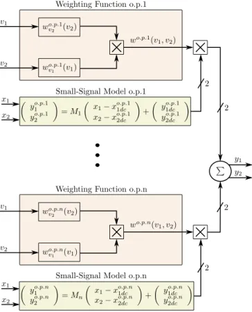
The idea behind this modeling approach is to describe the behavior of nonlinear systems obtaining small-signal models in different operation points and integrating them in a nonlinear structure by means of weighting functions. These models have been previously explored and validated in some applications [6]–[8], but a deeper analysis is required. There are several choices when it comes to design the polytopic model of a power converter. First, if the details of the converter are available, either state-space average or two-port models can be used as local models [9]. Nevertheless, this is not often the case in electronic power converter based systems, so in this paper blackbox two-port models are considered. In [10]–[12] the methodology to obtain these models is analyzed.
Fig. 3 depicts a scheme of the model structure. The operation points selected, xo.p.1dc1,x2o.p.dc1, ... ,xo.p.n1dc , xo.p.n2dc , and the mea-sured steady-state outputs, y1o.p.dc1,y2o.p.dc1, ... ,yo.p.n1dc ,yo.p.n2dc are used as dc bias for the obtained small-signal two-port models, M1, ..., Mn, which will depend on the variables considered
(G-parameters, Y-(G-parameters, etc). The same input signals,x1,x2,
will be inserted in each small-signal model, where each of them will subtract their nominal input dc value, xo.p.i1dc ,xo.p.i2dc . This difference with their nominal dc value is the signal inserted in the small-signal model,Mi. Finally, the small-signal output will be biased with the dc value of the output of each small-signal model, y1o.p.idc ,y2o.p.idc to obtain the final response around each operating point.
Also, the weighting functions associated with each small-signal model, wvo.p.1 1(v1), wvo.p.2 1(v2), ... , wo.p.nv1 (v1)
wo.p.nv2 (v2), can be designed independently for the different
variables taken into account,v1,v2, and multiplied afterward to
obtain the two-dimensional weighting surfaces,wo.p.1(v 1, v2),
... ,wo.p.n(v1, v2) of each small-signal model. In general, the
variables taken into account in the weighting functions will be equal to the inputs of the two-port models, but it is not a necessary condition. Actually, in [8] it was shown how for sharp load steps, a variable of the kind v = d(s)x gave more accurate results, as the transfer function d(s) can introduce information about the large-signal internal behavior of the converter. Finally, each small-signal model is multiplied by its corresponding weighting function, and the output of the nonlinear model will be the sum of all these weighted contributions of the small-signal models.
I I I
P
P
Figure 2: DC bus signaling strategy scheme. (a) Grid converter, (b) Renewable source converter, (c) Battery converter.
Figure 3: Polytopic model scheme.
ones, taking into account the type of converter and the values in which they will be used, and compare the Bode plots. Afterwards, if the shape of the plot is different, more points should be taken into account in the middle, otherwise if only the gain differs, a suitable design of the weighting functions should provide accurate results.
For the weighting functions there are also various possibil-ities, providing that their value is restricted to the range [0, 1] and the sum of all of them is always equal to the unity. The most common functions for this kind of application are the triangular function, which takes the unity value in the operation point in which the small-signal model was obtained and decreases linearly until it becomes zero in the adjacent ones and beyond; and the double-sigmoid function as the nonlinear option. The latter is used in this paper due to the flexibility that its parameters offer, these parameters are the
slope and the center of the sigmoid. Finally, there is not a mature methodology to tune the parameters of the weighting functions of the different small-signal models. In this work, as initial conditions, the intermediate value between adjacent selected points is always used for the center of the sigmoid and the minimum slope that reaches the unity value at the selected point. After, the model is compared with the target converter under different steps of the variable studied in order to further adjust the parameters.
A. Renewable source converter
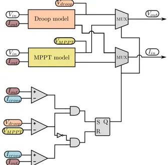
The converters interfacing RS should use MPPT control in order to utilize all the energy available. However, in case the nanogrid is not able to absorb this amount of power, they must change their control strategy to deliver just the power that is needed. Therefore, in those cases the converter will work regulating the bus voltage by means of droop control technique (see Fig. 2b).
In order to model a converter with different control strate-gies, it is necessary to obtain a model for each of them. In general a polytopic model of the converter working with each control strategy will be obtained, which will consider as many small-signal models as needed to model the behavior of the converter around the operating points of interest.
Modeling a converter with droop control was considered in [8]. G-parameters were used as the two-port small-signal models so the input voltage and output current were used as variables. Strictly speaking the droop parameter should be another input variable, however, in order to reduce the number of signals taken into account, its effect was approximated by modifying the dc value of the output voltage according to the droop equation (Fig.4).
Similarly, G-parameters can be used for the converter with MPPT control and the behavior of different power levels can be approximated by defining the dc output voltage as a function of the RS power:
VoutDC= P IDC
(1)
Accordingly, the input current, the other output variable, must be adjusted. Assuming the efficiency does not change considerably, the new input current could be modified as follows:
IinDC2=IinDC1·
P2
P1
Figure 5: Small-signal model including the MPPT control effect to consider a variable power delivered by the RS.
whereIinDC2is the input current with the new power level,
P2, and IinDC1 is the input current with the power level at
which the model was obtained,P1, (Fig. 5).
The transition between this two control techniques can be performed with weighting functions or by switching according to suitable conditions. The former is usually more appropriate considering the transition nature. The operating point around which the switch occurs, p1 of Fig. 2b, will be determined
by the intersection of the droop line and the constant power hyperbola in the V-I graph:
VDC−Kdroop·Icross = P
Icross (3)
Icross= Vdc Kdroop −
s
V
dc Kdroop
2
−4· P Kdroop
2 (4)
where VDC is the nominal voltage of the bus, Kdroop is the droop parameter, andP is the power delivered by the RS. Besides, in the moment of the switch the output voltage of the constant power model must be lower than the droop model to change from droop to MPPT and the opposite in the other direction. These conditions are depicted in Fig. 6.
A buck converter using the previous detailed control tech-nique has been designed in order to test the proposed modeling strategies, usingVdc= 24V,Kdroop= 0.15andP= 150 W. Two events are of special interest in this case, the transition from droop control to MPPT control and power changes.
Figure 6: Implemented conditions to switch from the response of droop to MPPT controlled polytopic models.
Fig. 7 focuses on the first situation. Three load steps are performed: after the first the converter still works using voltage droop control, the second causes the transition from droop to MPPT, and with the third it remains using MPPT. At the expense of clearness, in this figure some of the small-signal responses are depicted as well to illustrate the nonlinear behavior of the converter. It can be seen how the polytopic model smoothly changes among the different small-signal responses to accurately represent the converter behavior in this situation.
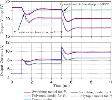
The second event is shown in Fig. 8. This time two dif-ferent experiments are represented together, only changing the maximum power level from P1 = 150 W, to P2 = 200 W.
The same two load steps are performed in both tests. After the first, in the case of P = 150W the converter enter in MPPT control mode, whereas in the case ofP = 200W the converter stays using droop control. Finally, with the second load step the converter with P = 200 W also move to MPPT control. The proposed model is shown to be in good agreement with the switching model behavior, representing the dependence of the transition from droop to MPPT with the power delivered by the RS, and also the steady-state and dynamic behavior with precision.
B. Battery converter
The converters interfacing batteries will, in general, work with constant current or droop control. The more suitable two-port model for current controlled converters is the Y-parameters (admittance Y-parameters). It considers a Norton equivalent model both for the input and the output of the converter (Fig. 9).
10 15 20 25 30
0 3 6 9 12
0 1 2 3 4
0 3 6 9 12 15
0,0 0,2 0,4 0,6 0,8 1,0
Figure 7: Performance of the proposed polytopic model for a buck converter using droop-MPPT control strategies.
io ii
=
Yo(s) Yoi(s) Horef(s) Yio(s) Yi(s) Hiref(s)
vo vi iref
(5)
whereHoref(s)andHiref(s)can be obtained analyzing the output and input current small-signal response with current ref-erence perturbations, when both the input and output voltages are kept constant.
In the next section these models will be used for system-level modeling. Also the integration of secondary-system-level control techniques into the polytopic model of the different converters will be discussed.
IV. SYSTEM-LEVEL MODELING
It is well-known that the connection of stable power con-verters may result in an unstable structure. Even if the new arrangement is stable, its dynamic behavior might be different than expected. G-parameters models have been used to assess
15 20 25
0 2 4 6 8 10
4 6 8 10 12
Figure 8: Performance of the proposed simplified model to take into account changes in the maximum power fromP1= 150W
toP2= 200W.
Figure 9: Admittance (Y) parameters scheme. (a) Equivalent circuit, (b) block diagram representation.
improve the current sharing among the converters using low-bandwidth frequency communication [15].
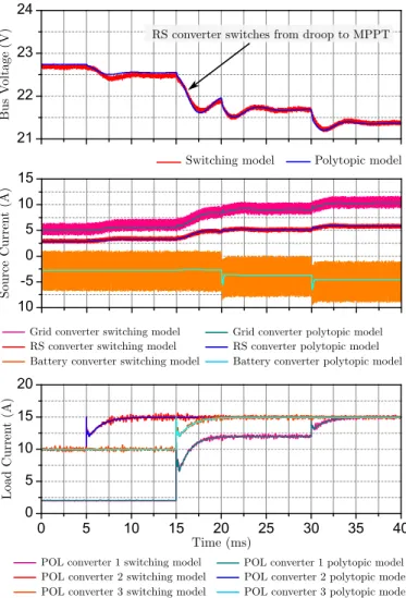
Fig. 1 depicts a microgrid scheme composed of three source converters that feed a24V bus: one connected to a renewable source, one connected to the grid or a higher level bus, and one connected to a battery. In addition, some POL (Point Of Load) converters are connected to the low voltage bus demanding variable power.
This microgrid has been designed using buck converters working with the control strategies previously detailed. Fol-lowing the methodology described in [8], a polytopic model of this microgrid has been obtained using a blackbox approach. The comparison can be seen in Fig. 10. In this simulation both grid and RS converters has aKdroop= 0.15. The solar panel is providing a powerP = 150W and the battery is recharging using constant current.
First, the RS converter is working in parallel with the grid converter using droop control. Despite they have the same droop parameter,Kdroop, their output current is different because they have different line resistances. At t = 5 ms there is a load step and the sources share the increase of current according to the droop control strategy. However, at t = 15 ms two simultaneous load steps cause that the RS converter switches to MPPT control. After, at t= 20 ms the battery increases the demanded current, when the RS converter is providing maximum power and the bus voltage is controlled by the grid converter. Finally, att= 30ms there is another load step and increase in the current demanded by the battery. It can be seen how the extra current is provided by the grid converter and the RS converter output current is adapted according to the deviation of the bus voltage, in order to keep its constant power. The polytopic models represent nicely all these effects. Following, the inclusion of the secondary level techniques in the polytopic model is studied.
A. Voltage restoration
A possible disadvantage of the droop control is the voltage deviation from the nominal value, which is used to share the current among the converters controlling the bus voltage in parallel. In case this deviation is troublesome, it can be restored using low-bandwidth frequency communication. The idea is to measure the voltage deviation of the bus and add this value, using a PI regulator, to all the voltage references of the converters working with droop control.
δv=Kp(VDC−Vbus) +Ki Z
(VDC−Vbus) (6)
Vref i=VDC−Kdroopi·I+δv (7)
where δv is the bus voltage deviation, Kp and Ki are the proportional and integral gains of the PI regulator,VDC is the nominal voltage of the bus,Vbusis the bus voltage, andVref i, Kdroopi are the voltage reference and the droop parameter of each of the converters using droop control.
21 22
-10 -5 0 5 10 15
0 5 10 15 20 25 30 35 40 0
5 10 15 20
Figure 10: Performance of the proposed polytopic model for a system-level simulation with changes in the operation mode of the converters.
In order to include this technique into the polytopic model, the dc output voltage of the small-signal models can be defined as the voltage reference. In case this approximation does not provide accurate enough results, a new transfer function should be included to consider the dynamic behavior of the converter under a change in the voltage reference, as it was explained for the case of current controlled converters. The input-output equations of the converter would be as follows:
vo
ii
=
G(s) −Z(s) Gref(s) Y(s) H(s) Yref(s)
vi io vref
(8)
23 24 25 26 27
0 5 10 15 20 25 30 35 40
0 3 6 9 12 15
Figure 11: Performance of the proposed polytopic model to simulate the effect of the voltage restoration control technique.
B. Current sharing
The other possible drawback is the effect of the line impedances on the current sharing among the converters reg-ulating the bus in parallel. As these impedances are not taken into account, they can unbalance the current delivered by each converter.
Again, by using low-bandwidth frequency communication it is also possible to deal with this problem. A possible solution is to measure the output current of each converter, obtain the arithmetic average value and modify the voltage reference of the converters with the error by means of a PI regulator.
iavg=
Pn j=1ij
n (9)
δii=Kp(iavg−ii) +Ki Z
(iavg−ii) (10)
Vref i=VDC−Kdroopi·I+δii (11)
whereiavgis the average value of the output currents of the converter,ij is the output current of each converter,n is the total number of converters that should have the same output current, andδii is the output current error of each converter. The incorporation of this strategy in the polytopic model can be performed in a similar manner as explained before for voltage restoration.
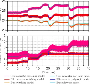
The previous simulation is repeated, but this time, at t = 10ms, the current sharing control is activated. The comparison is depicted in Fig. 12. It can be seen how the converter providing more current decreases its output voltage and vice-versa until their output currents are equalized. However, at t= 20ms the RS converter switches to MPPT control and the controls are not able to get both objectives due to the maximum power limitation.
These simulations show how the proposed modifications to the polytopic model can be useful to study the effect of
system-23 24 25 26
0 5 10 15 20 25 30 35 40
2 4 6 8 10 12
Figure 12: Performance of the polytopic model to simulate the current sharing control technique.
level control strategies from a blackbox perspective. Therefore, commercial converters can be tested individually in order to obtain their polytopic models and, afterwards, the techniques proposed can be added to the model in order to be able to simulate how they would behave together in a microgrid. Also the secondary control could be adjusted before the real microgrid has been assembled, avoiding unexpected failures.
V. CONCLUSION
Smart microgrids are expected to be composed of several commercial power converters. In order to be able to ensure an adequate system behavior before they are physically set up, suitable electrical models are required. The standard blackbox models usually use either linear approaches or they take into account static nonlinearities. However, it has been discussed that for microgrids using DBS this solution will normally be insufficient due to the wide range of possible operating con-ditions. In this paper the potential of the polytopic model for this application is studied by means of system level simulations containing several critical phenomena.
Voltage and current controlled converters has been ad-dressed, detailing the most suitable two-port models in each case. Also changes in the reference have been taken into ac-count. Regarding control strategies, converters that drastically change their control method are studied. Specially interesting is the case of RS interfacing converters, which change from droop control to MPPT according to the microgrid power state. Besides, simplified approaches to consider changes in droop parameters and variable RS generated power are proposed.
REFERENCES
[1] J. Schonberger, R. Duke, and S. D. Round, “DC-Bus Signaling: A Dis-tributed Control Strategy for a Hybrid Renewable Nanogrid,”Industrial Electronics, IEEE Transactions on, vol. 53, no. 5, pp. 1453–1460, 2006. [2] D. Boroyevich, I. Cvetkovic, D. Dong, R. Burgos, F. Wang, and F. Lee, “Future electronic power distribution systems a contemplative view,” in
Optimization of Electrical and Electronic Equipment (OPTIM), 2010 12th International Conference on, May 2010, pp. 1369–1380. [3] Y. Ito, Y. Zhongqing, and H. Akagi, “Dc microgrid based distribution
power generation system,” in Power Electronics and Motion Control Conference, 2004. IPEMC 2004. The 4th International, vol. 3, Aug 2004, pp. 1740–1745.
[4] J. Oliver, R. Prieto, J. Cobos, O. Garcia, and P. Alou, “Hybrid wiener-hammerstein structure for grey-box modeling of dc-dc converters,” in
Applied Power Electronics Conference and Exposition, 2009. APEC 2009. Twenty-Fourth Annual IEEE, Feb 2009, pp. 280–285.
[5] I. Cvetkovic, D. Boroyevich, P. Mattavelli, F. Lee, and D. Dong, “Non-linear, hybrid terminal behavioral modeling of a dc-based nanogrid sys-tem,” inApplied Power Electronics Conference and Exposition (APEC), 2011 Twenty-Sixth Annual IEEE, March 2011, pp. 1251–1258. [6] L. Arnedo, D. Boroyevich, R. Burgos, and F. Wang, “Polytopic
black-box modeling of dc-dc converters,” in Power Electronics Specialists Conference, 2008. PESC 2008. IEEE, June 2008, pp. 1015–1021. [7] S. F. Glover, “Modeling and stability analysis of a power electronics
based systems,” Ph.D. dissertation, Dept. Elect. Eng., Purdue Univ., Lafayette, IN, 2003.
[8] A. Francés, R. Asensi, O. García, R. Prieto, and J. Uceda, “A Black-box Modeling Approach for DC Nanogrids,” inApplied Power Electronics Conference and Exposition (APEC), 2016, pp. 1624–1631.
[9] T. Suntio, M. Hankaniemi, and M. Karppanen, “Analysing the dynamics of regulated converters,”IEE Proceedings - Electric Power Applications, vol. 153, no. 6, pp. 905–910, November 2006.
[10] L. Arnedo, D. Boroyevich, R. Burgos, and F. Wang, “Un-terminated frequency response measurements and model order reduction for black-box terminal characterization models,” in Applied Power Electronics Conference and Exposition, 2008. APEC 2008. Twenty-Third Annual IEEE, Feb 2008, pp. 1054–1060.
[11] I. Cvetkovic, D. Boroyevich, P. Mattavelli, F. Lee, and D. Dong, “Un-terminated, low-frequency terminal behavioral model of dc-dc convert-ers,” inApplied Power Electronics Conference and Exposition (APEC), 2011 Twenty-Sixth Annual IEEE, March 2011, pp. 1873–1880. [12] V. Valdivia, A. Barrado, A. Roldan, C. Fernandez, and P. Zumel,
“Black-box modeling of dc-dc converters based on transient response analysis and parametric identification methods,” in Applied Power Electronics Conference and Exposition (APEC), 2010 Twenty-Fifth Annual IEEE, Feb 2010, pp. 1131–1138.
[13] M. Hankaniemi, M. Karppanen, T. Suntio, A. Altowati, and K. Zenger, “Source-reflected load interactions in a regulated converter,” inIECON 2006 - 32nd Annual Conference on IEEE Industrial Electronics, Nov 2006, pp. 2893–2898.
[14] S. Vesti, J. A. Oliver, R. Prieto, J. A. Cobos, J. Huusari, and T. Suntio, “Practical characterization of input-parallel-connected converters with a common input filter,” in 2012 Twenty-Seventh Annual IEEE Applied Power Electronics Conference and Exposition (APEC), Feb 2012, pp. 1845–1852.