Development of a software tool for the analysis
and verification of emergency operating procedures through the
integrated simulation of plant and operators actions
A. Exposito , C. Queral , J. Hortal , A. Quiroga , A. Ibarra , J.E. Hulsund ,
I. Gonzalez , G. Jimenez
Department of Energy Systems, Technical University of Madrid, CIRios Rosas 21, 28003 Madrid, Spain
Abstract
Probabilistic safety assessment (PSA) includes operator actions as elements in the set of the considered protection performances dur-ing accident sequences. Nevertheless, its impact throughout a sequence is not usually analyzed dynamically. In this sense, it is convenient to make a more detailed analysis about its importance in the dynamics of the sequences, allowing for sensitivity studies with respect to human reliability and response times. For this reason, new developments in simulation software must be able to incorporate operator actions in conventional thermalhydraulic simulations. In this paper, we present one of these new tools, the TRETA/TIZONA-COPMA III coupled codes, which can be used for evaluating the impact in the final plant state of the execution by operators of procedures and the evaluation of the available times for the manual actions of the operators. This software tool consists of a closed-loop plant/operator simulator: a thermalhydraulic code for simulating the plant transient (TRETA for PWR NPPs and TIZONA for BWR NPPs) and the procedures processor (COPMA III) to simulate the operator actions requested by the procedures, both coupled by a data commu-nication system which allows the information exchange (SWBus). The first pilot cases have been performed in order to analyze sequences initiated by secondary side breaks leading to loss of heat sink sequences in a PWR plant. These tests have been carried out using the real plant EOPs for COPMA-III and a PWR plant model for TRETA code. The results of these simulations are presented in this paper.
1. Introduction
regarding how they may enhance the automatic actions or get into conflict with them.
In the framework of this issue, simulation-based human reliability analysis (HRA) methods seem to provide a new direction for the development of advanced methodologies to study the operator action effects during accident sequences (see for example Schryver, 1988; Chandraseka-ran et al., 1991; Cacciabue et al., 1992; Cacciabue, 1997; Jakubowski and Beraha (1996); Mosleh and Chang, 2004; Lee and Seong (2004)). Regarding these approaches, the simulation model for the performance assessment of nuclear power plants (NPP) operators is essential, implying the necessity to use simulation codes which include such effects in plant accident sequence simulations.
In the Spanish Nuclear Safety Council (CSN) there is a working group which has developed a simulation-based methodology, named the integrated safety assessment (ISA), considering these new methods. A key aspect of this approach is the automatic generation of dynamic event trees stemming from an initiating event, based on an efficient technique to simulate all branches while taking into account different factors which may affect the dynamic plant behavior in each sequence. This methodol-ogy is supported by a unifying theory which combines ele-ments of traditional deterministic and probabilistic analyses.
With regard to the consideration of the operator in the safety analysis, the development of new transient analysis methodologies integrating the operator actions and consid-ering human factors began at the 1990s, after the evalua-tion of the existing human factors methodologies and the proposal of its improvement, establishing the origin of the second generation HRA methodologies (Swain, 1990; Dougherty, 1990; Lydell, 1992; Bley et al., 1992). Addition-ally, there was a common opinion that design and valida-tion of procedures require to use better tools for their accomplishment (Hirschberg, 2004). Since 20 years ago, different tools are being developed to cover these needs. Most of them show some common characteristics that can be summarized as:
• They are based on cognitive theory, taking into account errors related to decision making, situation assessment and other cognitive processes.
• EOP computerization is based on task analysis (goals and means) or direct translation, considering or not con-sidering stochastic parameters during its simulation (execution time, EoC/EoO, . . . ) .
• Operator actions are integrated as boundary conditions in the input deck of usual plant simulators, or using dynamic approaches, based on different forms of simula-tion (CDETs, DDETs, . . . ) .
During the last years, the simulation of operator actions within the ISA methodology has been performed in several ways using different nature approaches, which are pre-sented and described in detail in this paper.
2. ISA methodology
New analysis methodologies can be developed based on the possibility of using a simulator driver that is able to generate tree-structured simulation sequences. These tech-niques, when combined with suitable methods for fault tree quantification, allow for the application of risk-oriented methodologies for various purposes, including the evalua-tion of Emergency Operating Procedures and Severe Acci-dent Management Guides. An example of such a methodology is the ISA, a systematic verification approach which can be considered as an extension of PSA and acci-dent analysis techniques, supported by the simulation sys-tem schematically represented in Fig. 1. The classical PSA static event trees are replaced by a generalized dynamic event-tree concept based on the theory of proba-bilistic dynamics (DDETs) (Devooght et al., 1996). Both components of the risk, damage and likelihood are consid-ered in this approach in a balanced and simultaneous way.
The main steps of this methodology are (Sanchez and Melara, 1996):
(1) Identification of damage variables and definition of risk acceptable regions in a frequency-damage plot. (2) Initiating event (IE) and initial state selection. (3) Modeling the deterministic characteristics of the
plant (plant dynamics modeling) including crew procedures.
BRANCHING POINT INFORMATION
SAVE-RESTART DATA
RESULTS: EVENT GENERATION
SAVE-RESTORE REQUESTS
RESULTS RISK LEVITT CHALLENGE
SAVE-RESTORE REQUESTS
SAVE-RESTART DATA
RESULTS: PROCEDURES
EXECUTION
(4) Modeling the stochastic characteristics of the plant (reliability modeling).
(5) Event sequence generation.
(6) Analysis of the results and verification of the risk requirements.
For a theoretical background and an in-depth descrip-tion of the different modules depicted in Fig. 1 (see Izquierdo and Sanchez, 1994; Hortal and Izquierdo,
1996; Izquierdo et al., 2002; Labeau and Izquierdo (2005a,b)).
3. Previous experience in the simulation of EOPs
A first approach of the CSN to consider the human actions in NPP transients, started in 1994, was the hard-coded implementation of the EOPs as modules of TRETA code. This integration of the EOPs in the simulation was named handbook of operating instructions (HOI), result-ing on the TRETA-HOI code version.
A full-scale application of TRETA-HOI was the inde-pendent verification of the event-tree delineation and com-putation of the SGTR initiating event of a Spanish PWR plant (Izquierdo and Sanchez, 1994; Sanchez and Melara, 1996). This study was carried out coupling TRETA-HOI with DYLAM for the calculation of DDETs. As a result of this work, a number of inconsistencies were found in the original delineation of the event tree, which were related to EOPs execution when combined with the com-plex plant dynamics involved and the large number of branches. Also, it was concluded that the critical point is to create a sufficiently flexible EOP model to deal with all possible outcomes of an accident sequence simulation.
Although this project finished with good results, it was concluded that some aspects of the HOI implementation could be improved:
• HOI had some functional limitations. For example, it was assumed that the crew follows the EOP instructions in a sequential way, not allowing parallel execution of different EOPs, as it is expected to occur in real situations.
• The EOP model was hard-coded, so any change of the model structure and parameters required edition of code sources files.
At the same time, and taking into account these draw-backs, a second approach was started to evaluate the via-bility of the computerization of procedures with COPMA-II, since this EOP simulation system allowed the comput-erization of EOPs in a flexible way, solving the limitations found in previous works. As a result of this new approach, in 1996, another project was initiated by the Department of Energy Systems group (DES), with the objective of developing a combined system relying on TIZONA-MAAP for plant simulations and on COP-MA-II for operator action implementation (Garcia and
Queral, 1997). The plant model for the combined tool was set up, including manual control inputs needed for procedure execution. This work concluded that COP-MA-II had several difficulties on the procedure computer-ization process, mainly tied to the procedures computerization language of this system, the Prola lan-guage. This issue, and the fact that COPMA-II was a machine dependent code, made this solution unworkable. For example, during the EOP computerization, it was considered necessary to add Prola instructions to code EOP steps related to actions which demanded manipula-tions over components (pumps, valves, ...) to control physical parameters. Prola is not designed to allow any change in its grammar, so the new functionality added to the COPMA-II kernel could only be achieved with the participation of the COPMA-II developing team, by modifying COPMA-II kernel source files, coded in lisp programming language. In addition, a high workload was necessary to understand the whole system architec-ture. This drawback has been solved partly in the new COPMA-III system version, which is highly modularized and based on user friendly flexible structures. Also, it is remarkable that after COPMA-II was developed, no sup-port team was in charge of its maintenance and the source code was not available, so any following application would have important difficulties and those requiring soft-ware modifications would be unaffordable.
4. Description of the present approach
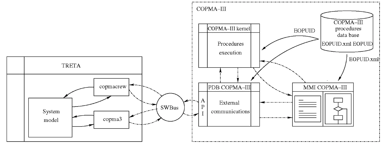
At present, a new approach to develop this tool has been carried out. This work started after the release of the new COPMA-III software version. The simulation programs that compound the simulation package are (Fig. 2)
(1) For the plant simulation the plant transient simulator codes TRETA and TIZONA are used for pressurized and boiling water reactors (PWR/ BWR) NPPs, respectively. These codes have been developed by the CSN including full scope models. The functional-ity of these thermalhydraulic codes has been expanded, allowing control of the overall information flow with external codes, simulating the TH transient and determining when the operator actions must be considered.
(2) The computerized procedure system is COPMA-III, developed by the OECD-Halden Reactor Project (HRP) and adapted with the contribution of the DES, CSN and HRP teams. It is able to manage an operational procedure database implemented in XML format.
(3) The information exchange between TRETA/TIZO-NA and COPMA-III is supported by the SWBus communication interface, also developed by HRP.
TRETA
System model
copmacrew
copma3 -—
v
< # • ' " ' '*"*•>.
* • - - » .
COPMA-III kernel
Procedures execution
A ! \/
PDB COPMA-III
External communications
EOPUID.xml!
\
"""-^. MMI COPMA-III _
_
1
Fig. 2. Schematic representation of the simulation package.
be used as an stand-alone code for a variety of purposes, such as:
• Realistic simulation of level 1 PSA sequences. • Supporting analysis for IPE and level 2 PSA.
• Design and verification of operating procedures, includ-ing Severe Accident Guides.
• Analysis of normal, abnormal and emergency scenarios in order to derive criteria for operator training or eval-uation activities.
For the shake of comparison, we can highlight, among the nowadays more developed support tools, the ADS-IDAC and the MDET-Crew module (Mosleh and Chang, 2004; Kloos and Peschke, 2007). ADS-IDAC is a tool based on DDET simulation which has a cognitive model (IDAC) to simulate most of the cognitive aspects consid-ered in the current HRA methodologies and the forthcom-ing second generation ones, for instance EoC, situation assessment and decision making. The plant dynamics are simulated using a RELAP5 in-house adapted version. MDET tool is a combination of Monte Carlo and DDET simulations taking into account operator actions in the simulation via a specific module, named Crew module. This module has a set of operator actuations (EOPs computer-ized steps) charactercomputer-ized with stochastic execution times and PSF, both calculated in execution time. In both tools, the EOP model is an abstraction using goals and means task analysis.
As previously described, ISA is a methodology with sim-ilar characteristics, also based on DDET simulation. Regarding the human actions simulation, TRETA/COP-MA-III coupled system presents a EOPs model with a var-iable detail level, which can range from a high abstraction degree up to individual instruction modeling, always using similar lexical elements than hardcopy procedures. There are similar tools, for example: EOP AS (Jakubowski and Beraha, 1996), ATOPS (Lee and Seong, 2004) and SCO-OPE/SIPA (Chatry and Poizat, 1999); but they are not ori-ented to be applied on PSA studies, just as it is the case of the ISA methodology.
TRETA/COPMA-III tool, within the framework of the ISA methodology, presents similar capabilities than MDET-Crew module. The stochastic parameters consid-ered in the simulations will be the time needed for task exe-cution, calculated taking into account different distribution functions, and the Human Error Probability (HEP), both calculated on running time. COPMA-III/TRETA system does not include a cognitive operator model in its present design. This means that cognitive errors, as EoC/EoO, could be taken into account during the EOP model com-puterization in a deterministic way. One of the most important advantages of this approach, compared with the other developments, is its highly modular implementa-tion. This characteristic will allow for using TRETA/COP-MA-III as a stand-alone tool to perform deterministic simulations.
In the next sections, the different elements of the TRE-TA/COPMA-III package are described in detail, enumer-ating their advantages from previous approaches.
4.1. TRETA and TIZONA codes
TRETA and TIZONA are modular simulation systems that are able to simulate virtually all the plant systems, including control, protection and balance of plant, and both include the necessary models to simulate PWR and BWR plants, respectively (Izquierdo et al., 2007). The ther-malhydraulic modules are based on elaborated models that combine a good representation of most of single and two-phase water regimes with a relatively fast solution algo-rithm. The implementation requirements respond to the following specifications:
• The code is not oriented to one specific type of application.
• Capability to perform tree-structured simulation, including event-tree automatic generation.
• Capability to incorporate other single-application ori-ented codes (i.e. RELAP5, MAAP, CONTAIN, ...) as modules using parallel computing techniques.
• Capability to parallelize the calculations, if the problem admits a parallel algorithm solution.
• Capability to admit different user-controlled numerical schemes, from explicit to fully implicit.
The system has been provided with specific routines that constitute open connections of the code, in such a way that other simulation programs may be integrated in the simu-lation of a physical system described by a block diagram. The connection capabilities are of two non-exclusive types, namely, initial conditions supply and boundary conditions exchange. To connect a code to the TRETA and TIZONA systems, certain communication routines must be inserted into it. The code should also have a structure compatible with the denned specifications.
4.2. COPMA-III code
COPMA-III is a procedure following system developed at the Halden Reactor Project (Bisio et al., 2000). It has been designed as an operator support system for guiding the execution of operating procedures. COPMA-III is con-nected to the plant process computer, or to a plant simula-tor, from which it receives the information needed for procedure execution.
Some of the most important aspects of this procedures simulation system are
• COPMA-III is a JAVA-based program, resulting on a more flexible system that its predecessor, COPMA-II. The communications library, process data base (PDB) and the system kernel are highly modularized, allowing to add new functionality for communications and proce-dures simulation for specific applications. It is also pos-sible to create rules for procedures management and execution as needed, making this system suitable for any reactor technology and procedure format (two-col-umn or flow chart). It is even not restricted to NPP procedures.
• New XPA (XML Processing for Antlr) structures and the new system kernel allow to create new instructions with different functions if it is needed, resulting in better EOPs modeling than with Prola language (COPMA-II). Both of them, XPA structures and system kernel, are designed to achieve at least the same semantic complex-ity than in paper procedures, if desired.
• XPA structures allow to change any simulation param-eter of the model without interfering in other parts of the simulation system and models. This is an advantage compared with HOI EOP model. Also, new parameters, managed by COPMA-III system or external codes can be included in the procedure model, so it is possible,
for example, to calculate execution times for each instruction taking into account plant and crew condition (workload, stress, . . . ) , updating them at run time. • The representation of the XPA procedure is made by
XML structures. Comparing with Prola (COMPA-II), XPA procedures provide a high degree of flexibility on the computerization process and a wide configuration capability on their visualization.
• COPMA-III can handle the execution of several proce-dures in parallel, or even several instances of the same procedure. The activity concept, denned as an instance of a procedure that is currently being executed, supports this capability. This means that the system kernel man-ages procedures in the same way that control room crew does. This feature, already present in COPMA-II, is an advantage with respect to HOI.
Although COPMA-III is much more suitable for EOP computerization, some efforts have been done to maintain some interesting features of COPMA-II. In particular, a set of translation tools has been developed to allow the conver-sion of Prola procedures to XPA-XML structures (Fig. 3). The interest in this translation capability arose from the existence of an important set of computerized procedures in this coding language. In addition, Prola procedures have some advantages for their maintenance, as compared to the new COPMA-III system. For example, the Prola language has a visual editor with useful tools (automatic flowchart diagram generation, logic condition visual builder, . . . ) , making the procedure coding more user-friendly. Besides, plain ASCII Prola files are human readable, allowing direct visual inspection, checking and modification.
4.3. COPMA-III and TRETAITIZONA communications
In its first release, COPMA-III software package was designed to be used in an interactive way via a m a n -machine interface based on HTML (Fig. 4). This means that any demand, condition evaluation or component manipulation, can be shown in the HTML interface and evaluated and executed by a user in real time.
However, COPMA-III can be used as a true procedure simulation system since this interface is a computer process that runs independently of the COPMA-III kernel and communicates with it. All of the operator interventions are received by the kernel as function calls resulting in instruction execution, information generation, etc. Due to this, COPMA-III can be used as an unattended simulator allowing automatic simulation via the module copma3 implemented in TRETA/TIZONA, which automatically generates the same function calls that the user would if using the MMI interface (Fig. 2).
PED-II (COPMA-II) Prola/XML-UID/XPA translator
PED-II
EOP
EOP.p
Pro la i |ANTLR/ANT]
Prola/XML
cz Z^
uid-gen.xsl L
-fd_ ~^
EOP.p.xml
f d Z2
csn-kerneLxsl
XML-UID to XPA
CLIENTLIB
Fig. 3. Prola to XML/XPA translator architecture.
Fig. 4. COPMA-III man-machine interface.
of the communications between the COPMA kernel and external codes, and the TRETA module responsible for communicating with COPMA-III, named copma3. The def-inition of the necessary functionality for the communica-tion has been developed and tested. For this purpose, the different functions implemented in the copma3 module are
• INITIALIZE_SESSION: It opens a new session with the COPMA system.
• SPWRF WRAPPER: Sets values of variables of the COPMA kernel. The variables can have numeric as well as symbolic values (e.g. 1 or 'OPEN').
• OPEN OPERATOR SUBSCRIPTION: This function subscribes the COPMA variables to be used by TRE-TA/TIZONA. Only the subscribed variables will be inspected, see P R O C V A R UPDATES. Subscribed variables within the session are returned only if their values have been changed since the last call to PROC VAR UPDATES or GET_EVALUATIONS_AND_ VALUES.
• TERMINATEJSESSION: This function closes a ses-sion opened by INITIALIZEJSESSION.
SWITCHTO_ACTIVITY: This function changes the cur-rent activity to some other running in the curcur-rent session. CREATE_ACTIVITY: This function creates a new activity in the current session to run the specified procedure.
GETJNSTRUCTIONJDETAILS: This function is used to obtain details about the current instruction, for instance the execution time in seconds of the current instruction or the percentage of the maximum work load - 100% - to be allocated by the operation team when the instruction was executed.
EXECUTEJCURRENTJNSTRUCTION: This func-tion is used to execute the current instrucfunc-tion and to obtain the label of the next instruction.
• END_ACTIVITY: This function finishes an activity started by CREATE_ACTIVITY.
The communications testing was done by means of sev-eral test procedures, which had the objective of performing a full range evaluation of the tool communications func-tionality (Figs. 5 and 6).
5. Plant and procedures models
The new combined system needs the definition of the following elements:
• A plant model for the TRETA/TIZONA codes, which must have the necessary interfaces to simulate the man-ual actions on the required plant systems or components.
• A procedures model with the most relevant steps of the real procedures, allowing it to simulate the scenario considered.
Both of them are described in the following sections.
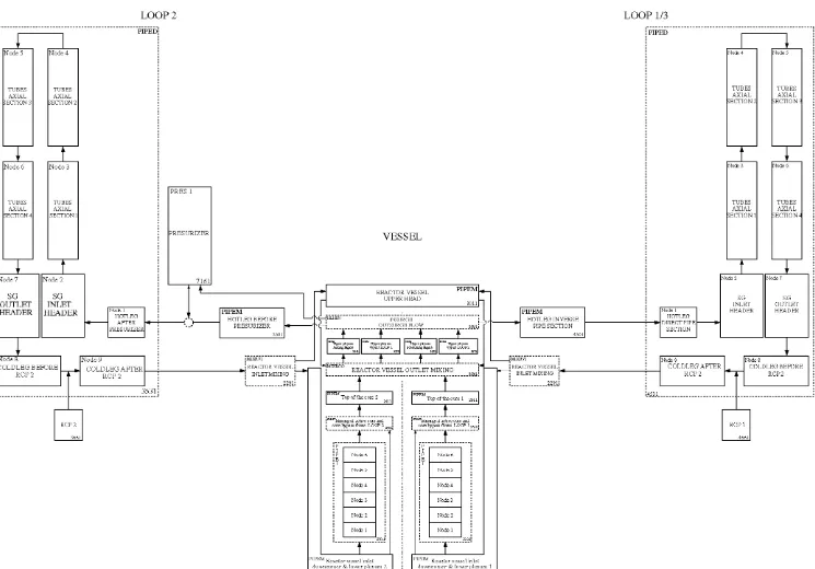
sends to TRETA the requests for operator actions derived from the procedures. Manual controls have been included in the plant model, being able to receive the action requests from COPMA-III. TRETA is designed to manage which parts of the simulation have to be computed by each code at every moment. When a manual action request is received from COPMA-III, TRETA addresses it to the right desti-nation. The capability for manual operation is not limited in TRETA, allowing the user to build as many manual con-trols as desired. The CSN has two plant models available for TRETA, namely Asco and Jose Cabrera, which have been verified with several transients. The DES group has finished the verification of a generic PWR-W NPP model (Exposito and Queral, 2003), which has been used for the first pilot cases. This model is composed of the following parts (Fig. 7):
• Vessel model.
• Two-loop reactor coolant system model. • Reactor cooling pumps model.
• Pressurizer model.
• Secondary side model based on two steam lines.
5.7. Plant model
The first stage of the work has been oriented towards the simulation of PWR plant transients, and the thermalhy-draulic code TRETA has been used for this purpose. It can simulate all kinds of plant systems including detailed automatic control. Besides, TRETA sends to COPMA-III information about the process variables needed to follow applicable operating procedures. COPMA-III, in turn,
The two-loop RCS model considers TH behavior simi-larities between the two loops without pressurizer to simu-late the TH transient in NPP with three loops (Spanish PWR NPPs have a RCS with three cooling loops).
The modeled engineered safeguards are the pressurizer and steam generators (SGs) relief and safety valves, steam and feedline isolation, safety injection and auxiliary feed-water (AFW) systems. Additionally, the possibility of fail-ure of one or more of these systems or their main
PDB LIB: Received message: ID=KC5
USER=CopmaServer HOST=vmware-winxp PID=IP0 UI0=d0e21
PROCEDURE=CIIITRT-SM-TETLUID UIDl=d0e7
UID2=d0e7
PDB LIB (GET_INSTRUCTION_DETAILS): SOI, CIIITRT-SM-TETLUID, 2
PDB LIB (INITITIALIZE_SESSI0N): AQ, c:\copmal_l\ProceduresDB\CSN\, vmware-winxp
PDB LIB (SBF_SPWRF_WRAPPER): numVars=6, VALENT.position=0, VALENT.opStatus=CLOSED, VALSAL.position=0, VALSAL.opStatus=CLOSED, MASA.value=100, SIMTIME.value=-5 PDB LIB (OPEW.OPERATOR.SUBSCRIPTIQN): S02, numVars=2, VALENT.command, VALSAL.command
PDB LIB (SBF_SPWRF_WRAPPER): numVars=2, VALENT.command=0, VALSAL.command=0
PDB LIB (GET_EVALUATIONS_AND_VALUES): SOI, numVariables (0), numMonitors ( 0 ) , numWaits (0), numActivities (0)
PDB LIB (SBF_SPWRF_WRAPPER): numVars=6, VALENT.position=0, VALENT.opStatus=CL0SED, VALSAL.position=0, VALSAL.opStatus=CL0SED, MASA.value=100, SIMTIME.value=0 PDB LIB (PR0C_VAR_UPDATES): S02 numVariables (2)
PDB LIB (GET_EVALUATIONS_AND_VALUES): S01, numVariables (0), numMonitors ( 0 ) , numWaits (0), numActivities (0) PDB LIB (EXECUTE_CURRENT_IMSTRUCTION): S01 CIIITRT-SM-TETLUID, IPO, 2, 1
PDB LIB (send_CK4): S01, CIIITRT-SM-TETLUID, IPO, 2,
PDB LIB: Received message: ID=KC11
USER=CopmaServer HOST=vmware-winxp UID1=VALENT.command UID2=0PEN
PDB LIB: Received message: ID=KC5
USER=CopmaServer HOST=vmware-winxp PID=IP0 UID=d0e35
P R O C E D U R E S IITRT-SM-TETLUID UIDl=d0e21
UID2=d0e21
components has been considered. The protection system model includes the automatic protection signals, including the capability of interaction with the operator. In parallel with the development of the PWR model, the DES group performed the Cofrentes NPP model for TIZONA code (Exposito et al., 2005). At this moment, the model has been validated and it is going to be used in the following simu-lations of BWR plant transients.
5.2. EOPs simulation
It can be remarked that there is a tight connection between the semantics of the procedure language and the
current functionality implemented in COPMA-III using XML semantics. In order to achieve this, the following instructions have been defined:
• ACTION: Specifies an action/component manipulation to be performed on a component.
• AUTOCHECK: Specifies a process condition to be automatically evaluated based on process variable val-ues. A GOSUB, GOTO or INITIATE instruction may be executed depending on the truth-value of the process condition.
• INITIATE: Creates an activity on a procedure. • FINISH: Terminates an activity.
variable 0: value: 0.990, name: VALENT.command, strval 0.99
GET_EVALUATIONS_AND_VALUES. RETURN: «GET-EVALUATIONS-AND-VALUES»-> error code: 0 NumOutputs: 0
NumMonitors: 0 Numwaits: 0 NumActivities: 0
-- TRETA:
Instruction 1 (WAIT type) of Step 3, Procedure CIIITRT-SM-TETLUID executed at time 10.000000
gettimeload query (COPMA-KERNEL:GET-INSTRUCTION-DETAILS :SESSION S01 :PR0C-ID (QUOTE CIIITRT-SM-TETLUID) :STEP-ID (QUOTE 4) :INST-ID (QUOTE 1)) GET_INSTRUCTION_DETAILS RETURN: <<GET_INSTRUCTION_DETAILS»-> error code: 0
STEP: Step: 4, INSTRUCTION: 1, TYPE: Message, Texec: 0, Taskload: 0
GET_EVALUATIONS_AND_VALUES. RETURN: «GET-EVALUATIONS-AND-VALUES»-> error code: 0 NumOutputs: 0
NumMonitors: 0 NumWaits: 1
WAIT 0: <Activity: IPO, Step: 3, Instruction: 1, status: 0> NumActivities: 0
GEL_EVALUATIONS_AND_VALUES. RETURN: «GET-EVALUATIONS-AND-VALUES»-> error code: 0 NumOutputs: 0
NumMonitors: 0 NumWaits: 1
WAIT 0: <Activity: IPO, Step: 3, Instruction: 1, status: 0> NumActivities: 0
GET_EVALUATIONS_AND_VALUES. RETURN: «GET-EVALUATIONS-AND-VALUES»--> error code: 0 NumOutputs: 0
NumMonitors 0 NumWaits: 1
WAIT 0: <Activity: IPO, Step: 3, Instruction: 1, status: 1> NumActivities: 0
-- TRETA:
Instruction 1 (MESSAGE type) of Step 4, Procedure CIIITRT-SM-TETLUID executed at time 70.000000
GET_INSTRUCTION_DETAILS RETURN: <<GET_INSTRUCTION_DETAILS»-> error code: 0 STEP: Step: 4, INSTRUCTION: 2, TYPE: Action, Texec: 30, Taskload: 100
PR0C_VAR_UPDATES
PR0C_VAR_UPDATES PASSED: RETURN: «PR0C-VAR-UPDATES»-> error code: 0 , Numoutputs: 0
GET_EVALUATIONS_AND_VALUES. RETURN: «GET-EVALUATIONS-AND-VALUES»-> error code: 0 NumOutputs: 0
NumMonitors: 0 NumWaits: 1
WAIT 0: <Activity: IPO, Step: 3, Instruction: 1, status: 1> NumActivities: 0
-- TRETA:
Instruction 2 (ACTION type) of Step 4, Procedure CIIITRT-SM-TETLUID executed at time 100.000000
GET_INSTRUCTIONS_DETAILS RETURN: «GET_INSTRUCTION_DETAILS>>-> error code: 0 STEP: Step: 4, INSTRUCTION: 3, TYPE: Action, Texec: 30, Taskload: 100
PR0C_VAR_UPDATES PASSED: RETURN: «PR0C-VAR-UPDATES»--> error code: 0 , Numoutputs: 1
variable 0: value: 0.010, name: VALENT.command, strval 0.01
1
Nods 5
TUBES AXIAL !ECTION3
1
TUBES AXIAL iECTION 2
LOOP 2
"PIPED:
1
Node 6
TUBES AXIAL SECTION 4
t
Node 3
TUBES AXIAL SECTION 1
LOOP 1/3
! PIPED
PRESURLZER
1
TUBES AXIAL SECTION 2
1
TUBES AXIAL
SECTION;
JZ
I I
Fig. 7. Scheme of a PWR RCS model for TRETA code.
GOSUB: Causes the control flow to jump to a specified instruction in the procedure. The first following RETURN instruction will let the flow of control return to the first instruction following the last executed GOSUB.
GOTO: Causes the flow of control to jump to a specified instruction with no implicit link to a following RETURN instruction.
MONITOR: Similar to AUTOCHECK but the condi-tion is monitored within a specified time interval. RETURN: Causes the flow of control to return to the first instruction following the last executed, non-returned GOSUB instruction.
WAIT: Prevents the execution of the next instruction until the indicated time interval expires or the specified process condition is met.
Table 1
Memory structure for the valve component
Valves (valvecomponent)
Management Attribute Value Comment
TRETA/TIZONA
COPMA-III
User
position Numeric value opStatus OPEN, CLOSED,
CLOSING . . . autoStatus AUTO, MAN command Numeric value
autoSwitch ON, OFF
openval Constant numeric value closeval Constant numeric value
Valve opening Valve states
Valve operating mode
When the procedure demands an action on the valve
VALVE, COPMA-III changes the VALVE.commmand attribute, in particular: - OPEN VALVE.command sets VALVE.command to the value specified in
VALVE.openval
- CLOSE VALVE.command sets VALVE.command to the value specified in VALVE.closeval
This set of instructions is enough for procedures com-puterization, and its functionality has been tested during the computerization of the Westinghouse (PWR) and Gen-eral Electric (BWR/6) EOPs, and it could be improved if necessary.
With regard to EOPs, a review of the previous experi-ence in this kind of simulation was performed and, in a sec-ond stage, a generic methodology was selected to perform the procedure computerization (Queral et al., 2003). This methodology establishes:
• Guidelines for computerizing the different elements pres-ent in EOPs:
- Action steps: distinguishing among steps which demand logic or numerical validations (logic or numerical statements) on the plant components/sys-tems state or physical variables (AUTOCHECK), continuous monitoring of physical variables or plant components/systems state (MONITOR), specific actuation demand on plant components/systems (ACTION) and transitions to other procedures or
Step 11
11.2
Step 13
11.1
If level in tank BP-20 < 30 % gotoEOP-E-23B.
Start DG-3
12.a.2
Start PIS auxiliar pump
12.b.2
Check maximun aperture for valve PIS 1FCV
Yes
Step 15
guides (INITIATE). Also, it establishes the required functionality to model immediate action steps, con-tinuous steps, evaluation of physical variables time evolution during the transient and steps implying control actions during a time interval.
- Cautions and notes: providing rules to computerize them as actions steps (specific or continuous) or spe-cial operational modes for plant systems or compo-nents under punctual conditions.
- Foldout page: establishes the computerization of the actions informed on it as continuous monitoring steps which are applicable at any step in the procedure or procedure series. The most important of these actions are procedure transitions which allow immediate response to new symptoms as they appear.
- FRGs status trees: defines the computerization of these trees as logic statements based on a set of AUTOCHECK instructions checked each minute using a WAIT instruction. This short checking time period is used due to FRGs status trees are monitored by the safety parameters display system (SDPD), and automatic monitoring system supervised by the operators.
• Defines the memory structures and their attributes to manage information related to physical model parame-ters and components/systems status:
- Types of components: valves and pumps (e.g. Table 1).
- System operation modes. - Physical variables.
Two important simulation parameters have been imple-mented for the manual actions demanded by EOPs and computerized in the COPMA-III procedures data base. First one is related with the time required for instruction execution by operators, and it can be obtained from several sources, one of them is the operator training timing in full-scope simulators. For an example about how this data can be extracted from training sessions (see Park et al., 2005; Park and Jung, 2006, 2007). These data are usually aver-aged for different sequences and operator psychological states and experience skills. An example of a first applica-tion of these data source using the COPMA-III/TRETA simulator is provided in the next section. Another data source could be the application of the discrete event simu-lation (DES) methodology. This methodology is being applied to obtain in a systematic way execution times for unitary operator actions (see for example Yow et al., 2005). The second parameter is related with the workload, psychological and physical, which is assumed by the con-trol room crew during the execution of the simulated instruction. Nowadays, the notion of workload in this con-text and the objective methods for assessing it are under investigation. One of the most relevant research work in this direction is the one carried out by the KAERI human factor working group. Within the scope of this research, this group is assessing the existing methodologies to quan-tify workload and complexity of the operator actions demanded by EOPs (Jung et al., 2001; Park et al., 2001, 2004). Both research lines, DES and task load methodolo-gies tested by the KAERI working group, have been
• Additionally, the methodology establishes the steps to computerize procedures in a proper manner:
(1) It specifies the modeling detail level for plant sys-tems and components.
(2) It clarifies the plant physical parameters which are important to execute the procedures.
(3) It guides in the computerization of actions over components (pumps/valves), to control physical parameters within a range.
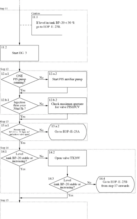
By way of illustration, a simple procedure has been com-puterized using this methodology. The first task consists of obtaining a task flow diagram from the procedure, consid-ering the procedure instructions of interest for the simula-tion (Fig. 8). Next, it is necessary to identify, one by one, each task action verb with a computerized instruction (Table 2) and to define the variables needed to manage the information related with this instructions, identifying plant systems, components or physical parameters (Table 3). Finally, the computerization can be carried out, and the obtained computerized procedure should have the same functionality than the hardcopy procedure, as it can be checked by comparing the original task flow diagram with the computerized task diagram (Figs. 8 and 9).
Table 2
Type of steps, defined tasks and computerized instructions related to the example procedure Step 11 12 13 14 Considered subtask 11.1 11.2 12.a.l 12.a.2 12.b.l 12.b.2 13.a.l 14.1 14.2 14.3 14.4 Instruction MONITOR ACTION AUTOCHECK ACTION AUTOCHECK ACTION
MONITOR with INITIATE AUTOCHECK
ACTION AUTOCHECK INITIATE
Table 3
Some of the defined tasks, computerized instructions and variables related to the example procedure
Considered subtasks 11.1 11.2 12.a.2 14.1 Instruction MONITOR ACTION ACTION AUTOCHECK
Type of variable
physmagnitude generalvariable pumpcomponent physmagnitude Variable name BP20LEVEL.ua/ue
considered in the implementation of the TASKEXEC and TASKLOAD parameters, and its future results will be tested and applied when the tool is developed.
6. Application of the simulation package to the total loss of secondary heat sink
In this section, the application of the simulation package to procedures simulation is described. First part is dedi-cated to the methodology developed for the computeriza-tion of the EOPs and its applicacomputeriza-tion to the sequences that have been simulated. The following section
corre-sponds to the simulation of the transients selected as pilot application and the results obtained.
6.1. Analysis of the EOPs and their computerization
The sequences selected for checking the tool functional-ity have been the total loss of secondary heat sink. An in-depth study was carried out to define the detail and scope of the procedures model (Exposito and Queral, 2004):
(1) FSAR sequences related to TLFW and SLB were studied.
Step 11
11.1
MONITOR
BP20LEVEL.raZi(e
11.2
ACTION
DG3.mode
Step 15
(2) PSA studies were analyzed, extracting the informa-tion related to human acinforma-tions considered for these sequences. When possible, EOPs and steps regarding backup and mitigating actions were identified. As a result of this work a simplified event tree for these sequences was depicted (Fig. 10).
(3) These EOPs were revised, seeking for which of them were used in each event-tree sequence, allowing to establish the computerized EOPs model structure. The computerization of the most relevant EOPs related with this kind of sequences was carried out (Exposito et al., 2006): reactor trip (E-0), reactor trip response (ES-0.1), loss of primary or secondary cool-ant (E-l), response to loss of heat sink (FR-H.l), loss of recirculation capability (ECA-1.1), safety injection (SI), termination (ES-1.1) and transition to SI recir-culation (ES-1.3).
(4) Emergency response guidelines basis were revised to clarify the task and goals involved in the actions com-puterized and to verify that its functionality covered the original designed one.
(5) The final stage of the work was the review of the sci-entific and technical bibliography about these kind of transients considering technical reports, NUREGs, papers, etc. The objective was to get a detailed knowl-edge of the plant phenomenology for these sequences, to acquire a general view of the associated problem-atic and to define the plant physical parameters of interest.
During the computerization process, it was carried out a preliminary testing to check the EOP execution, using man-ual simulation of operator actions. This task permitted the detection of the need to improve COPMA-III to manage EOP hierarchy (ORG/FRG). In its current version, it is
possible to take into account it implicitly, but it is necessary to implement this functionality explicitly in the EOP model attributes.
Also, it has been necessary to interpret some steps of the EOPs, especially those that require operator judgment of the plant conditions, like in manual control of the AFW flow during a loss of feedwater. In this sense, it was con-cluded that EOP computerization is the most delicate stage of the simulation model development, being necessary the interaction with operators and operators trainers to under-stand which are the real actuations performed by operators in some situations.
Fig. 10 depicts a generic PSA tree for the total loss of secondary heat sink sequences and the related procedures. The motivations for this selection were that these sequences are well known and that they are complex enough to test the simulation package functionality.
For these sequences, the main objectives specified in EOPs, highly summarized, are (Exposito and Queral, 2004):
• To check and verify the correct actuation of all the sys-tems and safeguards demanded. The actuations per-formed by the operator to verify and control the AFW flow and the RCS temperature are included in this category.
• To start the feed and bleed cooling procedure in case of loss of secondary heat sink.
These and other less relevant operator actions have been implemented in the COPMA-III computerized procedures (Table 4). All the interfaces needed for these manual actions have been included in the PWR model for TRETA code. The manual controls implemented actuate as required by EOPs and their main objective is to establish
5 £ §
o < 2
« a s OT ffi OS
RELEASE RE-LCLOSED Damage
ES 1.3 ECA 1.1
ES 1.3 F R - H . l
No
No
Yes
Table 4
Main operator actions implemented in computerized EOPs and plant model for TLFW sequences
Operator action EOP-STEP Code reference
StopRCPs FR-H.1-3 A-RCPSTOP RCS depressurization FR-H.l-6b A-RCSBLOW Secondary depressurization FR-H.l-6e A-SGBLOW Start RCS feed FR-H.1-9 A-RCSFEED Start RCS bleed FR-H.1-12 A-RCSBLEED
• A-RCSBLOW: RCS depressurization to establish opti-mal conditions for initiating RCS feed.
• A-SGBLOW: secondary depressurization for making possible the SGs feed by means of the condensate pumps.
• A-RCSFEED: initiates the RCS feed running two CVCS high pressure pumps.
• A-RCSBLEED: initiates the RCS bleed opening two pressurizer PORVs.
Table 5
Averaged time for EOP E-0 execution and event diagnosis time from reactor trip for LSLB, TLFW, LOCA, LOOP, SBO and SGTR sequences (Park et al., 2005)
Table 6
Event diagnosis time from reactor trip for LOOP, loss of RHRS, SGTR, LOCA, loss of heat sink and LNFW sequences (Villemeur et al., 1986)
Initiating event (EOP) Average
LOOP (I4B)
Loss of RHRS (IRRA2) SGTR (A3)
LOCA (A10)
Loss of heat sink (Hl.l) LFW (H2)
Average
6 min 50 s 2 min 15s 12 min 6 min 10 s 3 min 5 s 2 min 50 s 5 min 32 s (332 s)
7 min 24 s 6 min 45 s 1 min 24 s 6 min 2 min 5 s 1 min 28 s 3 min (180 s)
Table 7
Task completion time data in coping with TLFW (Park et al., 2005)
Task Time average Standard
(s) deviation (s)
Stoppage of all RCPs 415.4 246.3 Securing the water inventory of SGs 556.9 137.6 Checking criteria for F&B 565.6 286.4 Confirming the natural circulation 791.6 161.8
of RCS
steady and safe conditions after the correct actuation of protection systems and safeguards. Some of their specifica-tions are:
• A-RCPSTOP: stops RCPS to take advantage of the remaining inventory in the SGs during loss of heat sink sequences.
Regarding the executing time implemented for every action computerized in the EOPs model, a preliminary approach was carried out, using data from timing operator
DBA
LSLB TLFW LOCA LOOP SBO SGTR
Performance time of the diagnosis
Average (s)
182.4 137.2 135.8 106.7 101.3 195.9
EOP
<x(s)
72.4 89.8 47.8 39.9 55.3 106.7
Diagnosis time from reactor
Averag
412.7 300.8 357.5 271.7 251.7 403.6
trip
5 ( S ) <x(s)
128.7 157.8 134.9 79.4 78.6 199.1
REACTOR SCRAM
E - 0 ES-0.1
PS 1
TEi.
F-0
CSFs status tree monitoring
S (F-0.1)
Subcriticality
C (F-0.2)
Core cooling
training in full-scope simulators (Tables 5-7). The data obtained from Tables 5 and 6 were used to establish the time needed to start E-0 EOP, while the data of Table 7 were used for the different actions computerized in the F R G FR-H.l, described in detail in the next section.
6.2. Simulation results for the first pilot case: total loss of secondary heat sink
The initiating event of the transient is a break located at the normal feedwater header at 120 s (the event sequence is presented in Table 11). This event brings out the loss of normal feedwater, remaining unavailable during the tran-sient. After this moment, the SGs level loss leads to the reactor scram at 149.63 s (low SG level signal in both SGs) (Fig. 14). This signal involves the AFWS actuation, however, the most important assumption in this simulation is that this safeguard system fails.
The turbine trip is induced by the reactor scram at 149.74 s. Because of the fast SGs depressurization at the beginning of the transient and the unavailability of any feedwater flow source (Figs. 15 and 16), the CSF monitor-ing tree related with the heat sink is in red condition at
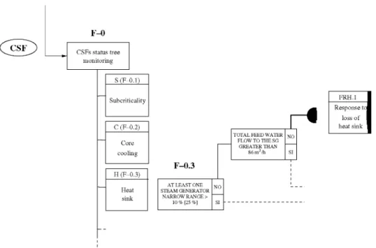
166.4 s (Fig. 12). That is 48 s after the reactor scram. This fact would imply the transition to the FRG H.l at that moment if the control room crew checked the FRG state in the SPDS display. However, in the simulation, this aspect has not been considered, taking into account only the CSF monitoring when it is demanded by the EOPs. This consideration postponed the entry in F R G H.l in the simulation until 470 s, instead of 166.4 s.
The subsequent evolution of the transient is determined by the manual actions performed by the operator. The
most important required by the F R G H.l are (Table 4, Fig. 13):
• Manual RCPs trip, task CD.
• RCS and secondary depressurization, tasks © and ®. • Feed and bleed criteria monitoring and execution of the
maneuver, tasks ® and © .
• To establish steady cooling conditions and lower the RCS pressure to values below the LPIS delivery head (these actions are not considered in the current simulations).
The execution of the EOP E-0 is initiated at 300 s, 150 s after the reactor scram (see Table 8) verifying the auto-matic actuation of the reactor protection system and the core subcritical condition, steps 1-3 (Fig. 11). Afterwards, the EOP ES-0.1 is initiated, reactor trip response, at 410 s. This transition to EOP ES-0.1 is possible since the RCS and SGs pressures are below 130 and 48.1 kg/cm2 (Figs. 17 and 18) not considering the SI actuation.
As of this moment, the monitoring of the CSFs status tree (F-0) is initiated simultaneously with the EOP ES-0.1 execution. Considering 60 s as the time spent in CSF state checking using the SPDS, at 470 s the ES-0.1 EOP is left, transferring the execution to the FRG H.l, response to the loss of heat sink (Table 9). During this time interval, the strong decrease of the SGs inventories continues due to the actuation of the steam dump bypass (Figs. 15 and 16).
The first operator action demanded by the FRG H.l is the RCPs stopping at 725 s, step 3 of the procedure (Fig. 13). The RCPs stopping is unconditional, mainly due to the fact that the loss of SG inventory is reduced
F-0
CSFs status tree monitoring
S (F-0.1)
Subcriticality
C (F-0.2)
Core cooling
H (F-0,3)
Heat sink
F-0.3
TOTAL FEED WATER FLOW TO THE SG
GREATER THAN 86m3/h
r*
FRH.l Response t<
loss of heat sink
AT LEAST ONE STEAM GENERATOR
NARROW RANGE > " 10 % [25 %]
FR-H.l Steps 12
Step 6 i
6.b.l
Lower the RCS pressure below 140 k g / c m2
TE6.i,.!
J_
6.e
Lower the SGs pressure below 28 k g / c m2
TEe.e
No
F&B Yes
F&B
Step 9
ki"
Start manual feed (SI)
TE9.1
Step 12 12.1
Start manual bleed 2 PORVs opened
TE1 2.i
Fig. 13. E O P structure for t h e loss of total feedwater transient: F R G F R - H . l a n d F & B m a n u a l actions.
Fig. 14. T o t a l loss of feedwater: S G s n a r r o w r a n g e level.
T a b l e 8
Assigned time for E O P E-0 subtasks
S u b t a s k
E n t r y 1-3.1 4.1
T a b l e 9
Assigned time for E O P ES-0.1 subtasks
S u b t a s k
E n t r y 1-5.1
T E ( s )
150 80 30
T E ( s )
I) RCPs manual trip
» F & B : bleed started
0 200 400 600 800 1000 1200 1400 1600 Time (s)
Fig. 15. Total loss of feedwater: SGs wide range level.
"a
~T
PZR PORVs Safety Injection Steam Dump SGsFW
JU_
Time (s)
Fig. 16. Total loss of feedwater: total SGs FW, SD, HPSI (manual actuation), and PZR PORVs mass flows.
Table 10
Assigned time for EOP FR-H.l subtasks
Subtask TE (s)
Entry 1-2.1 3.1 4-6.a.l 6.b.l 6.c-d.l 6.e.l 7.a-b.l 8.1 9.1 10-11.1 12.1 13-18.1 19.1 20.1
60 120 75 60 30 20 30 50 60 95 30 30 300 30 30
in natural circulation and the RCPs coolant heating is avoided, providing more time for SG inventory recov-ering actions and, therefore, increasing the
possi-bilities for avoiding the execution of the F&B cooling maneuver.
Heat sink recovery actions related with feeding the SGs by means of the condensate system imply the primary and secondary depressurization to 140 and 28 kg/cm2. These actions, instructions 6.b y 6.e of the FR-H.l procedure, are performed at 815 and 865 s respectively (Table 10, Figs. 17 and 18). While these actions are performed, the inven-tory of the SGs is diminishing, reaching the F&B condition at 870 s (Fig. 15). Considering that the recovery of the AFWS and the feed by means of the condensate pumps are impossible due to simulation assumptions, the evalua-tion of this condievalua-tion is made at 975 s, initiating the feed to the RCS by means of the SI manual actuation at 1070 s and the bleeding of the primary at 1130 s, steps 9 and 12 of FR-H.l (Fig. 16). Finally, the simultaneous actu-ation of feed and bleed tends to establish steady conditions in RCS pressure and temperature, as shown in Figs. 17 and 19. The final state consists of a dynamic balance of the feed and the bleed depending on the volumes of the income and
-1 ' -1 ' -1 ' -1 '
V 71
RCS depressurization *F&B: feed started
1 ' 1 ' 1 '
F&B: bleed
started-r
A
/ \
\ ]
0 200 400 600 800 1000 1200 1400 1600 Time (s)
Fig. 17. Total loss of feedwater: RCS pressure.
8e+06
7.5e+06
7e+06
6.5e+06
J
l 1 ' 1 ' 1 ' 1 ' 1 ' 1 ' 1 '
-^ — _ \
\
\
\ / ^
1 , 1 , 1 , 1 , 1 , ^ l , 1
0 200 400 600 800 1000 1200 1400 1600 Time (s)
350
340
330
U ^ 3 2 0
I 310
I
H 300
1~75 ' ' ' 'J^-* RCS depressurization r
F&B: btexl startal Cold leg L I Hot led LI Averaged L I Cold leg L2 Hot leg L2 Averaged L2 Reference Saturation
Time (s)
Fig. 19. Total loss of feedwater: temperatures in the RCS.
outcome flows, the residual heat and the RCS pressure (Loomis and Cozzuol, 1988).
The pressure is the most important system variable to assess long term cooling with low pressures, as it is required by EOPs to allow LPSI delivery. Several studies have been carried out to establish which is the optimal F&B proce-dure for lowering pressure to those values, taking into account different time windows depending on the amount of residual heat (Lanore et al., 1987; Champ and Cornille, 1989) or different configurations for feed and bleed (one/ two HPSI pumps and one/two pressurizer PORVs) (Demuth et al., 1982; Loomis and Cozzuol, 1988). This issue is not considered in our study, finishing the simula-tion when the feed and bleed flows tend to be steady, regardless of the steady pressure value.
7. Conclusions
TRETA/COPMA-III coupled system is capable to per-form simulations integrating the effect of operator actions in the nuclear plant state during transient and accidental sequences. This tool is based on a EOPs model with a var-iable detail level, which can differ from a high abstraction degree to an instruction by instruction computerized EOP version, always using similar lexical elements than hard-copy procedures. TRETA/COPMA-III tool, within the framework of the ISA methodology, presents similar capa-bilities than other software tools that are currently under development and testing, MDET-Crew module or ADS-ID AC. The stochastic parameters considered in the simula-tions will be the execution time, calculated taking into account different distribution functions, and HEP calcula-tion in execucalcula-tion time. Finally, EoC and EoO can be taken into account as configurable boundary conditions in the EOPs model. One of its key aspects, and an advantage compared with the other developments, is that indepen-dently of its implementation as a part of the ISA method-ology, this tool can be used as a stand-alone code for evaluating the impact of procedures and guidelines execu-tion by operators in the final state of the plant and the eval-uation of the available times for manual actions of the operator in a flexible way.
At this stage of the work, several practical tests have been carried out and all functionality needs denned for the TRETA/COPMA-III tool have been validated. The coupled codes are capable of simulating single sequences with all the requirements of testability and repeatability. When this part of the work is finished, a more ambitious simulation exercise will be undertaken for analysis of the
Table 11
TLFW: manual and automatic actions timing sequence
Time (s) Description
Automatic actuations
120 149.63 149.74
Main normal feedwater header break (loss of normal feedwater)
Low SGs level signal. Reactor scram and AFWS actuation demand signals. AFWS failed (total loss of feedwater) Turbine trip
Manual actions!operator performance
166.4 300
410
470 725 815 865 870 975 1070.15 1130 1500
Red condition in CSF (SPDS): F-0.3 status tree - FR-H.l F R G EOP entry (EOP E-0)
Event diagnosis is assumed (TLFW) SI is unnecessary. Task 4.1
Transitioned to EOP ES-0.1. Task 4.1 CSF status tree monitoring initiated. Transitioned to FRG FR-H.l. Task 1-5.1 Manual RCPs trip (A-RCPSTOP). Task 3.1 RCS depressurization (A-RCSBLOW). Task 6.b.l Secondary depressurization (A-SGBLOW). Task 6.e.l F&B condition becomes true
F&B entry condition is evaluated. Task 8.1
F&B maneuver: RCS feed initiated (A-RCSFEED). Task 9.1 F&B maneuver: RCS bleed initiated (A-RCSBLEED). Task 12.1
impact of EOPs execution by operators in the final state of the plant and the evaluation of the available response times for manual actions. Furthermore, more improvements have been considered although the development stage of the software tool is nearly finished.
On the other hand, emergency operating procedures need to be evaluated in a PSA context where multiple sequences starting from the same operating conditions have to be considered. In particular, the simulation codes should be able to communicate with a general driver, known as the simulation scheduler, and to receive some signals from it asking for storing or retrieving a particular simulation spot, or to suspend, finish or restart the simu-lation of a particular sequence. In its current degree of development, COPMA-III does not include these features yet. It is expected, however, that they will be incorporated in the near future and that the applicability of the com-bined tool can be extended to the automatic simulation of dynamic event trees, just as it is needed for the final implementation of the tool as a part of the ISA methodology.
Acknowledgements
This work was supported by CSN. Their support is gratefully acknowledged.
References
Bisio, R., Hulsund, J.E., Nilsen, S, 2000. Brief Introduction to the COPMA-III Tool. Halden Reactor Project. Institute for Energy Technology. Available Online.
Bley, D., Kaplan, S., Johnson, D., 1992. The strengths and limitations of PSA: where we stand. Reliability Engineering and System Safety 38, 3 -26.
Cacciabue, P.C., 1997. A methodology of human factors analysis for systems engineering: theory and applications. IEEE Transactions on Systems, Man and Cybernetics - Part A: Systems and Humans 27 (3), 325-339.
Cacciabue, P.C., Decortis, F., Drozdowicz, B., Masson, M., Nordvik, J.P., 1992. COSIMO: a cognitive simulation model of human decision making and behavior in accident management of complex plants. IEEE Transactions on Systems, Man and Cybernetics 22 (5), 1058— 1074.
Champ, M., Cornille, Y, 1989. Evaluation of feed and bleed cooling mode in case of total loss of feedwater on 900 MWe PWR. In: CSNI Specialist Meeting on International Coolant System Depressur-ization.
Chandrasekaran, B., Bhatnagar, R., Sharma, D.D., 1991. Real-time disturbance control. Communication of the ACM 34 (8), 33^47. Chatry, J-P., Poizat, F. 1999. A safety breakthrough: EDF computerized
emergency operation approach. In: 7th International Conference on Nuclear Engineering, ICONE-7037. ICONE.
Demuth, N.S., Dobranich, D., Heninger, R.J., 1982. Loss of feedwater transients for the zion-1 pressurized water reactor. Technical Report NUREG/CR-2656. Los Alamos National Laboratory.
Devooght, J., Izquierdo, J.M., Melendez, E., 1996. Relationships between probabilistic dynamics and event trees. Reliability Engineering & System Safety 52, 197-209.
Dougherty, E., 1990. Guest editorial: human reliability analysis - where shouldst thou turn? Reliability Engineering and System Safety 29 (3), 283-300.
Exposito, A., Queral, C , 2003. Almaraz NPP model for TRETA code. Technical Report DSE-18/2003. Department of Energy Systems of the Technical University of Madrid (in Spanish).
Exposito, A., Queral, C , 2004. Analysis of the secondary breaks sequences. Technical Report DSE-01/2004. Department of Energy Systems of the Technical University of Madrid (in Spanish).
Exposito, A., Queral, C , Carballo, J., 2005. Cofrentes NPP model for TIZONA code. Technical Report DSE-11/2005. Department of Energy Systems of the Technical University of Madrid (in Spanish). Exposito, A., Queral, C , Quiroga, J.A., Ibarra, A., 2006. PWR EOPs
computerization for COPMA-III system by means of the developed tools. Technical Report DSE-32/2006. Department of Energy Systems of the Technical University of Madrid (in Spanish).
Garcia, M.A., Queral, C , 1997. Specific agreement CSN-UPM for the development of evaluation instruments of accident management guides. Technical Report DSE-UPM-97. Spanish Nuclear Safety Council (in Spanish).
Hirschberg, S., 2004. Human reliability analysis in probabilistic safety assessment for nuclear power plants. Technical Opinion Papers 4, CSNI.
Hortal, J., Izquierdo, J.M., 1996. Application of the integrated safety assessment methodology to the protection of electric systems. Reli-ability Engineering & System Safety 52, 315-326.
Izquierdo, J.M., Sanchez, M., 1994. Application of the integrated safety assessment methodology to the emergency procedures of a SGTR of a PWR. Reliability Engineering & System Safety 45 (1-2), 159-173. Izquierdo, J.M., et al., 2002. An integrated PSA approach to independent
regulatory evaluations of nuclear safety assessments of Spanish nuclear power plants. Technical Report 28.2002. Spanish Nuclear Safety Council.
Izquierdo, J.M., Sanchez, M., Hortal, J., Melendez, E., Herrero, R., Queral, C , Exposito, A., Gonzalez, I., 2007. TRETA and TIZONA fast running thermal-hydraulic codes. Annals of Nuclear Energy 34 (7), 533-549.
Jakubowski, Z., Beraha, D., 1996. An expert system-based aid for analysis of emergency operating procedures in NPPs. In: Nuclear Society of Slovenia (Ed.), Ill Regional Meeting: Nuclear Energy in Central Europe. Nuclear Society of Slovenia.
Jung, W.D., Kim, J.W., Ha, J. J., 2001. A study on development of the step complexity measure for emergency operating procedures using entropy concepts. Technical Report KAERI/TR-1794/2001. KAERI. Kloos, M., Peschke, J., 2007. Consideration of human actions in
combination with the probabilistic dynamics method MCDET. In: Conference Record for European Safety and Reliability Conference (ESREL).
Labeau, P.E., Izquierdo, J.M., 2005a. Modeling PSA problems - I: the stimulus-driven theory of probabilistic dynamics. Nuclear Science and Engineering 150, 115-139.
Labeau, P.E., Izquierdo, J.M., 2005b. Modeling PSA problems - I I : a cell-to-cell transport theory approach. Nuclear Science and Engineering 150, 140-154.
Lanore, J.M., Caron, J.L., Ellia-Hervy, A., L'Henoret, J., 1987. Interac-tion between thermal-hydraulics, human factors and system analysis for assessing feed and bleed risk benefits. In: International SNS/ENS/ ANS Topical Meeting on Probabilistic Safety Assessment and Risk Management.
Lee, S.J., Seong, P.H., 2004. Development of automated operating procedure system using fuzzy colored petri nets for nuclear power plants. Annals of Nuclear Energy 31, 849-869.
Loomis, G G , Cozzuol, J.M., 1988. Decay heat removal using feed-and-bleed for US pressurized water reactors. Technical Report N U R E G / CR-5072. Idaho National Engineering Laboratory. EGG-2526. Lydell, B.O.Y., 1992. Human reliability methodology. A discussion of
the state of the art. Reliability Engineering and System Safety 36, 15-21.
Park, J., Jung, W., 2006. The appropriateness of the systematic framework to develop diagnosis procedures of nuclear power plants - an experimental verification. Reliability Engineering and System Safety 91, 53-65.
Park, J., Jung, W., 2007. OPERA - a human performance database under simulated emergencies of nuclear power plants. Reliability Engineering and System Safety 92 (4), 503-519.
Park, J., Jung, W., Jaewhan, K., Jaejoo, H., Yunghwa, S., 2001. The step complexity measure for emergency operating procedures: comparing with simulation data. Reliability Engineering and System Safety 74, 63-74.
Park, J., Kim, J., Jung, W., 2004. Comparing the complexity of procedural steps with the operators' performance observed under stressful conditions. Reliability Engineering and System Safety 83, 79-91. Park, J., Jung, W., Kim, J., Ha, J., 2005. Analysis of human performance
observed under simulated emergencies of nuclear power plants. Technical Report KAERI/TR-2895/2005. KAERI.
Queral, C , Quiroga, J.A., Exposito, A., Ibarra, A., 2003. Methodology and tools used for the computerization of the Almaraz NPP EOPs. Technical Report DSE-12/2003. Department of Energy Systems of the Technical University of Madrid (in Spanish).
Quiroga, J.A., Ibarra, A., Exposito, A., Queral, C , 2006. TRETA/ TIZONA and COPMA-III communication implementation. Technical Report DSE-31/2006. Department of Energy Systems of the Technical University of Madrid (in Spanish).
Sanchez, M., Melara, J., 1996. Extending PSA to accident management: the case of the steam generator tube rupture (STGR). Emergency operating procedures assessment. In: Proceeding of the International Conference on Nuclear Engineering (ICONE), vol. 3. ASME. Schryver, J.C., 1988. Operator model-based design and evaluation of
advanced systems: computational models. In: Conference Record for 1988 IEEE Fourth Conference on Human Factors and Power Plants, pp. 121-127.
Swain, A.D., 1990. Human reliability analysis: need, status, trends, and limitations. Reliability Engineering and System Safety 29, 301-313. ViUemeur, A., Moroni, J.M., Mosneron-Dupin, F., Meslin, T., 1986. A
simulator-based evaluation of operators' behavior by Electricite de France. In: Proceedings of the International Topical Meeting on Advanced in Human Factors in Nuclear Power Systems, Knoxville, Tennessee, pp. 374-379. Yow, A., Walters, B., Plott, B., Laughery, R., Persensky, J., 2005.