sensors
ISSN 1424-8220
www.mdpi.com/journal/sensors
Article
Experimental Implementation of a Biometric Laser
Synaptic Sensor
Alexander N. Pisarchik1,2,*, Ricardo Sevilla-Escoboza3, Rider Jaimes-Re´ategui3,
Guillermo Huerta-Cuellar3, J. Hugo Garc´ıa-Lopez3 and Victor B. Kazantsev4,5
1 Centro de Investigaciones en Optica, Loma del Bosque 115, Lomas del Campestre, Leon 37150,
Guanajuato, Mexico
2 Centre for Biomedical Technology, Technical University of Madrid, Campus Montegancedo,
Pozuelo de Alarcon 28223, Madrid, Spain
3 Centro Universitario de Los Lagos, Universidad de Guadalajara, Enrique D´ıaz de Le´on 1144,
Paseo de la Monta˜na, Lagos de Moreno, Jalisco 47460, Mexico;
E-Mails: [email protected] (R.S.-E.); [email protected] (R.J.-R.); [email protected] (G.H.-C.); [email protected] (J.H.G.-L.)
4 Institute of Applied Physics of Russian Academy of Science, 46 Uljanov Str.,
Nizhny Novgorod 603950, Russia; E-Mail: [email protected]
5 Lobachevsky State University of Nizhni Novgorod, 23 Gagarin Ave.,
Nizhny Novgorod 603950, Russia
*Author to whom correspondence should be addressed; E-Mail: [email protected]; Tel.: +52-477-4414-200; Fax: +52-477-4414-209.
Received: 26 October 2013; in revised form: 27 November 2013 / Accepted: 3 December 2013 / Published: 16 December 2013
Abstract: We fabricate a biometric laser fiber synaptic sensor to transmit information from
Keywords: fiber laser; electronic circuit; neuron; synapse; artificial intelligence; neuroengineering; biorobotics; pump modulation
1. Introduction
The human brain consists of approximately one hundred billion neurons interconnected in a complex way to perform computational, cognition and memory tasks. Neurons usually interact via synapses, which allow information transmission from one cell to the other. Each neuron has an average of 7,000 synaptic connections. Being subserved by a complex molecular mechanism, the synapses are capable of changing the efficiency of signal transmission between neurons by sensing electrical activity and chemical concentrations. It is believed that the flexibility of the synaptic connections (e.g., synaptic plasticity) underlies the implementation of computational and cognitive tasks in brain networks. While in living cells, the synaptic plasticity is mediated by complex molecular transformation, in an artificial biosystem, the synaptic transmission can be regulated by adjusting the parameters of an artificial synapse. Significant efforts have been made to represent a synapse by a single device that mimics synaptic connections and behavioral flexibility. This challenging task for biorobotics would allow a direct linkage between neuroscience and artificial intelligence. Any attempt to construct an artificial brain must consider its complexity. Several attempts have already been made. For example, Sharpet al. [1] used an electronic circuit to couple two living stomatogastric ganglia neurons. Synaptic behavior has also been imitated by hardware-based neural networks, such as hybrid complementary metal-oxide-semiconductor analogue circuits and other artificial neural devices [2–4] capable of mimicking the major features of human memory; namely, sensory, short-term and long-term memories. Great progress in nanotechnology has provided significant advances in the miniaturization of synthetic synapses, e.g., the fabrication of a carbon nanotube synaptic circuit [5]. Artificial synaptic devices based on ion migration have been also designed [6]; some of them [7,8] have demonstrated spike-timing-dependent plasticity [9], the important mechanism of brain memory, related to the synaptic connection strength in biological circuits and synthetic devices. These devices require precise control of the signal timing to simulate the pre- and post-synaptic potentials in biological systems.
Recently, we have proposed an optical synaptic sensor based on an erbium-doped fiber laser (EDFL) to establish a functional connection between FHN electronic neurons [15]. We have numerically shown that this laser synapse allows one to control the spike transmission with a very high flexibility. The distinguished features of the laser synapse from other artificial (electronic) synapses are: (1) an optical carrier (optical radiation in the IRspectral range) instead of an electric current; (2) optical fiber transmission instead of a metallic wire; and (3) very rich dynamics, including fixed points, periodic orbits with different frequency-locking ratios and chaos.
In this work, we report on the first, to the best of our knowledge, experimental implementation of the laser synapse and demonstrate its high flexibility in controlling signal transmission from a pre-synaptic to a post-synaptic neuron.
2. Experimental Setup
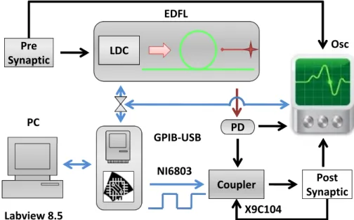
The experimental setup is shown in Figure 1. The EDFL is pumped by a laser diode (wavelength: 976 nm) through a wavelength-division multiplexing coupler and a polarization controller. The laser cavity of a 1.55-m length is formed by a piece of erbium-doped fiber of 70 cm in length and 2.7 µm in core diameter and two fiber Bragg gratings with a 2-nm FWHMbandwidth and with 90.5% and 94% reflectivity at a 1,550-nm wavelength. The diode pump laser is controlled by a laser diode controller (LDC) (Thorlabs ITC510).
Figure 1. Experimental setup. The pre-synaptic FitzHugh–Nagumo (FHN) electronic
circuit drives the erbium-doped fiber laser (EDFL) via the laser diode controller (LDC). The signal from the photodetector (PD) after passing through the coupler controls the post-synaptic FHN electronic circuit. The output signals from the pre-synaptic neuron, laser and post-synaptic neuron are recorded by the oscilloscope (Osc) and stored in the computer (PC) using the GPIBcommunication protocol and Labview 8.5. The square signal generated by the NI6803 card is applied to the digital potentiometer, X9C104, to control the coupling strength.
!"#$ !"#$
%&'()*+, -./
0.1-23,
!43*$ !43*$ %&'()*+, /45)6#"
!/
7!89:;%9
<8=>?@
AB/C?D -(EF+#G >HI
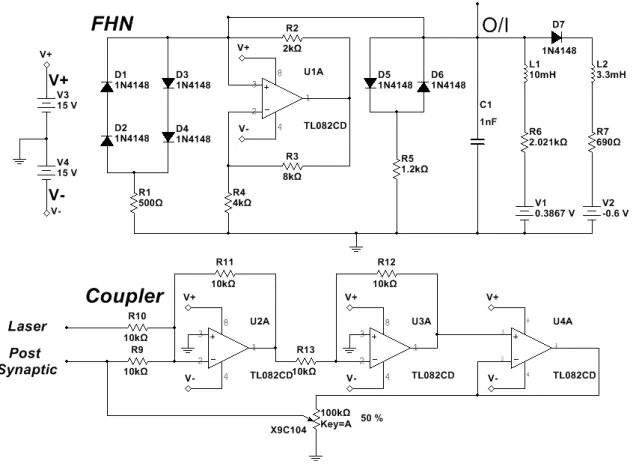
The diode pump current of the EDFL is modulated by the pre-synaptic neuron. The optical output of the EDFL is converted to an electrical signal by the photo-detector and sent through the coupler to the post-synaptic neuron. Figure 2 shows the electronic schemes of the FHN circuit and coupler [13,14].
The EDFL output power depends linearly on the diode pump current,I, as shown in Figure 3a. The lasing threshold is 107 mA. Figure 3b shows the optical spectrum of the EDFL.
Figure 2. Electronic schemes of FitzHugh–Nagumo and coupler circuits.
Figure 3. (a) EDFL output power versus diode pump current and (b) the EDFL
optical spectrum.
0 100 200 300
0 10 20 30 40
EDFL wavelength, λ (μm)
EDFL output power,
U
(mW)
Diode pump current, I (mA)
3. Results and Discussion
3.1. Synaptic Transfer Function
Before connecting the pre-synaptic neuron to the post-synaptic neuron, we measure a transfer function of the laser synapse. The transfer function is a frequency response of the synapse to an input signal. This important characteristic provides us with information about the frequency resolution of the synaptic sensor,i.e., its sensitivity to input frequency. Figure 4 shows the frequency resolution of the laser synapse (blue traces) and the post-synaptic neuron (red traces) to a harmonic signal applied to the laser pump current. The input frequency is indicated on the left-hand side of each time series.
Figure 4. Laser (blue traces) and post-synaptic neuron (red traces) responses to harmonic
modulation at (a) low, (b) middle and (c) high frequencies. The amplitude of the input signal applied to the laser pump current from a signal generatorA= 1V, andI = 125mA.
0 . 0 0 0 . 2 5 0 . 5 0 0 . 7 5 1 . 0 0 - 0 . 5
0 . 0 0 . 5 1 . 0 1 . 5 2 . 0 - 0 . 5 0 . 0 0 . 5 1 . 0 1 . 5 2 . 0 - 0 . 5 0 . 0 0 . 5 1 . 0 1 . 5 2 . 0 - 0 . 5 0 . 0 0 . 5 1 . 0 1 . 5 2 . 0
P o s t - s y n a p t i c n e u r o n L a s e r
f = 3 0 .4 k H z
T i m e ( m s ) ( c )
f = 3 9 .6 k H z f = 4 2 .8 k H z f = 5 5 .4 k H z
0 . 0 0 . 5 1 . 0 1 . 5 2 . 0 - 0 . 5
0 . 0 0 . 5 1 . 0 1 . 5 2 . 0 - 0 . 5 0 . 0 0 . 5 1 . 0 1 . 5 2 . 0 - 0 . 5 0 . 0 0 . 5 1 . 0 1 . 5 2 . 0 - 0 . 5 0 . 0 0 . 5 1 . 0 1 . 5 2 . 0
( b )
P o s t - s y n a p t i c n e u r o n L a s e r
f = 1 1 .8 k H z
T i m e ( m s )
f = 2 0 .6 k H z f = 2 3 .6 k H z f = 2 7 k H z
0 . 0 0 . 5 1 . 0 1 . 5 2 . 0 - 0 . 5
0 . 0 0 . 5 1 . 0 1 . 5 2 . 0 - 0 . 5 0 . 0 0 . 5 1 . 0 1 . 5 2 . 0 - 0 . 5 0 . 0 0 . 5 1 . 0 1 . 5 2 . 0 - 0 . 5 0 . 0 0 . 5 1 . 0 1 . 5 2 . 0
( a )
P o s t - s y n a p t i c n e u r o n L a s e r
f = 1 k H z
T i m e ( m s )
f = 2 k H z f = 5 k H z f = 7 .2 k H z
Figure 5. Bifurcation diagrams of (a) laser peak intensity and (b) post-synaptic neuron
inter-spike-interval (ISI) using modulation frequency as a control parameter. A = 1V, and I = 125mA.
1 0 2 0 3 0 4 0 5 0 6 0 0 . 0
0 . 1 0 . 2 0 . 3 0 . 4 0 . 5
P o s t-s y n a p ti c n e u ro n I S I
M o d u l a t i o n f r e q u e n c y ( k H z ) ( b )
0 1 0 2 0 3 0 4 0 5 0 6 0 0 . 0
0 . 1 0 . 2 0 . 3 0 . 4 0 . 5 0 . 6 0 . 7
0 . 8 ( a )
L a s e r p e a k i n te n s it y ( m V )
For very low input frequencies (Figure 4a), a train of the laser and post-synaptic neuron spikes emerges at every period of the input signal. Inside each train of pulses, the synapse and post-synaptic neuron respond at different frequencies, and the number of spikes in the train decreases as the input frequency is increased. At higher frequencies (Figure 4b), it can happen that the post-synaptic neuron either stays silent (forf = 23.6kHz), or there is a spike train (forf = 20.5kHz andf = 27kHz) regime while the laser emits a pulse at every period of the input signal. For high frequencies (Figure 4c), the response of the post-synaptic neuron to a chaotic laser input can be either periodic (forf = 30.4kHz) or irregular (forf = 55.4kHz). All these and other regimes can be distinguished in the bifurcation diagrams of the laser peak intensity and the post-synaptic neuron inter-spike-interval (ISI) shown, respectively, in Figure 5a,b.
While the bifurcation diagram of the laser peak intensity is the transfer function of the laser synaptic sensor, the ISI is the transfer function of the system formed by the laser and the post-synaptic neuron. The diversity of dynamical regimes obtained in the laser and its high sensitivity to the input frequency indicate a high flexibility of the laser synapse that can be beneficial for controlling signal transmission from one neuron to the other.
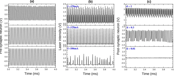
Figure 6. Time series of the (a) pre-synaptic neuron, (b) laser and (c) post-synaptic
neuron. The laser response in (b) displays the 2:3 (upper trace) and 1:1 (middle trace) frequency-locking and chaotic (lower trace) regimes, while the post-synaptic neuron response in (c) exhibits the 2:3 (upper trace), unlocked (middle trace) and silence (lower trace) regimes.
3 . 0 3 . 2 3 . 4 3 . 6 3 . 8 4 . 0 - 1 . 0
- 0 . 5 0 . 0 0 . 5 1 . 0 - 1 . 0 - 0 . 5 0 . 0 0 . 5 1 . 0 - 1 . 0 - 0 . 5 0 . 0 0 . 5 1 . 0
( a )
T i m e ( m s )
P re -s y n a p ti c n e u ro n ( V )
3 . 0 3 . 2 3 . 4 3 . 6 3 . 8 4 . 0 0 . 0
0 . 5 1 . 0 1 . 5 2 . 0 2 . 5 0 . 0 0 . 5 1 . 0 1 . 5 2 . 0 2 . 5 0 . 0 0 . 5 1 . 0 1 . 5 2 . 0 2 . 5
T i m e ( m s )
I= 1 2 9 m A
L a s e r in te n s it y ( V )
( b )
I = 1 7 8 m A
I = 1 0 6 m A
3 . 0 3 . 2 3 . 4 3 . 6 3 . 8 4 . 0 - 1 . 0
- 0 . 5 0 . 0 0 . 5 1 . 0 1 . 5 - 1 . 0 - 0 . 5 0 . 0 0 . 5 1 . 0 1 . 50
1
2
3
4
T i m e ( m s )
P o s t-s y n a p ti c n e u ro n ( V )
( c )
d = 0 . 0 1 d = 0 . 3 d = 1
3.2. Neuron Connection