TítuloComparison of two stage and single stage biofiltration for H2S and toluene co treatment
8
0
0
Texto completo
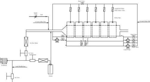
(2) 96. S. GRACY, C. HORT AND V. PLATEL. The first stage is designed to remove H2S at low pH condition. In this stage, an inert, acid resistant medium is used. The second stage is designed to remove VOCs at neutral pH. Because H2S removal is confined to the first stage, there is no acid production in the second stage. However, there are still some researchers studying co-treatment of a mixture gas of H2S and VOCs in a single bioreactor and getting some good performances (Todd et al., 1996; Ergas et al., 1995). Thus, the performances of a two-stage biofilter and a single-stage biofilter for H2S and toluene co-treatment were investigated to study their feasibility and applicability. A horizontal style was designed to realize two stages in one tank and lower the pressure drop. 2 MATERIALS AND METHODS The horizontal biofilter consisted of six segments. The size of each segment was 15cmx15cmx10cm (WidthxHeightxLength) with a volume of 2.25L. Five of them were packed with Calgon carbon and the other one was kept empty for flexible operation. Water and nutrients were added by a sprinkler recycling system. The upper two sumps were for two-stage biofilter and the lower sump was for single-stage biofilter. There were two water valves to contact the upper and lower sumps. When the reactor operated as single-stage biofilter, the water valves were open. Or else when as a two-stage biofilter, they were closed. The schematic diagram of the biofilter is shown in Figure 1. Water Valve. Liquid Flow Meter With Control Valve Needle Valve. H2S Telfon Tube 1/2 inch Telfon Tube. 1/4 inch Telfon Tube. Water Valve Water Valve. Air Flow Meter. Water Valve Liquid Pump Air Valve. Air Blower. 1 inch Flexible hose. toluene Air Valve. Figure 1. Schematic diagram of the horizontal biofilter.. The toluene waste gas was produced by passing air through a bottle containing pure liquid toluene. High concentration H2S in gas cylinder was controlled by a regulator and a flow meter to get the desired H2S gas stream. With dilution of bulk ambient airflow, the combined gas stream was channeled through the reactor. In the two-stage biofilter, Thiobacillus sp. were inoculated at low pH in the first stage. Pseudomonas putida was then inoculated in the second stage at neutral pH. This provided the optimum survival environment for bacteria growth thus enhancing the overall efficiency and effectiveness in the biofilter system. The neutral pH biofilter (single-stage) was inoculated by a mixture of Thiobacillus sp. and Pseudomonas putida..
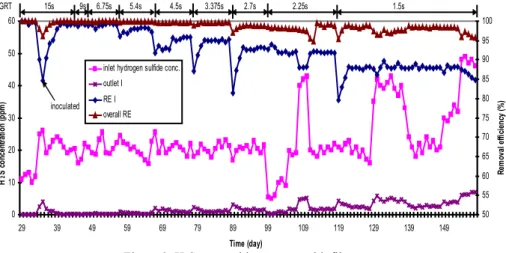
(3) COMPARISON OF TWO-STAGE AND SINGLE-STAGE BIOFILTRATION FOR H2S AND TOLUENE CO-TREATMENT. 97. These two species of bacteria are ubiquitous and symbiotic at neutral pH in wastewater treatment. The packing material was granular activated carbon (GAC) of diameter 4 mm, supplied by Calgon Co. (Pittsburgh, PA). Gas samples were collected using Tedlar bags and measured immediately after sampling. H2S concentration was measured by Jerome 631X Hydrogen Sulfide Analyzer (USA). Toluene analysis was accomplished with a Hewlett Packard 5890 gas chromatograph (GC) with a Flame Ionization Detector (FID). Sulfate content was measured by gravimetry according to 4500-SO42- Standard Method. The operating parameters are shown in Table 1. Table 1. Operating Parameters of the horizontal biofilter. Single-stage Two-stage biofilter Operating Parameter biofilter First stage Second stage Packing media volume (L). 11.25. 2.25. Inlet gas. H2S. 5-50. Concentration(ppm). Toluene. 10-300. GRT(s). 9-60. Gas flow rate (L/min) pH of recirculation solution. 1.5-15. 9. 6-60. 9-90 6.0-8.0. 1.0-3.0. 6.0-8.0. 3 RESULTS AND DISCUSSION 3.1 Biofilter performances At the beginning, only toluene gas was fed in. Pseudomonas putida was inoculated after carbon bed breakthrough. When toluene removal was stabilized above 95%, H2S was introduced. Gas retention time (GRT) and inlet concentration was changed step by step to test these two key parameters influence on system performance (Figure 2~5). 3.1.1 Two-stage biofilter GRT in Figure 2 and 3 refers to first stage GRT and second stage GRT, respectively. The legend “RE I” represents the first stage removal efficiency. “Outlet I” is gas outlet concentration from the first stage. Most H2S was removed by the first stage. Overall H2S removal was higher. After 60 days’ operation, the second stage was contaminated by H2S degraders. A number of H2S degrading bacteria were detected in the second stage leachate. According to Figure 3, the biofilter was re-inoculated on day 12 because the system was shut down for maintenance of the recirculation system. On day 63, toluene removal efficiency dropped quickly due to biofilm clogging and then recovered after washing. From day 113 to 118, no data were recorded because of GC malfunction. Toluene removal of the first stage was unstable. The first stage outlet concentration was found sometimes higher than inlet concentration. No toluene degraders were found in the first stage during bacteria counting. The removal mechanism was mainly carbon adsorption, not bacteria degradation. Toluene was mainly treated in the second stage. Inlet H2S concentration increased approximately to 50ppm on day 154. The second stage was acidized quickly because of the high H2S outlet from the first stage. pH of the second stage dropped to 1.9. Biofilm with carbon power sloughed into the recirculating water.
(4) 98. S. GRACY, C. HORT AND V. PLATEL. and made it dark. To assure overall high performance, H2S outlet from first stage is suggested to be lower than 3ppm. GRT not shorter than 3s/12s (H2S/toluene) is suggested for high gas mixture removal efficiency. GRT. 15s. 9s. 6.75s. 5.4s. 4.5s. 3.375s. 2.7s. 2.25s. 1.5s 100. 60. 95 50. 90. H 2 S concentration (ppm). 40 inoculated 30. outlet I. 85. RE I. 80. overall RE. 75. Removal efficiency (%). inlet hydrogen sulfide conc.. 70 20. 65 60. 10. 55 0. 50 29. 39. 49. 59. 69. 79. 89. 99. 109. 119. 129. 139. 149. Time (day). Figure 2. H2S removal in two-stage biofilter.. 60s. GRT. 36s 27s. 21.6s. 18s. 13.5s. 10.8s. 6s. 9s. 100 300. reinoculation. 90. inlet toluene conc.. 80. overall RE RE I. 250. 70. Toluene concentration (ppm). clogging. 50 40. 150 add H 2S. 30 20. 100. 10. Removal efficiency (%). 60 200. 0. 50 inoculation. -10. 0. -20 0. 10. 20. 30. 40. 50. 60. 70. 80. 90. 100. 110. 120. 130. 140. 150. 160. Time (day). Figure 3. Toluene removal in two-stage biofilter.. 3.1.2 Single-stage biofilter To maintain the biofilter pH at neutral level, caustic soda was added every day. To avoid comsumption of large amount of alkali, H2S concentration was set at a lower level (5ppm). In the following figures, RE I is H2S removal efficiency of the first cell. RE I decreased from 99% to 90% as GRT decreased. However, the overall removal efficiency was always 100% because of the long overall GRT. Toluene removal followed similar to H2S. When GRT varied from 60s to 9s, the removal efficiency fell from about 100% to 87%. With increasing inlet concentration, both RE I and toluene removal efficiency dropped accordingly at a short constant GRT..
(5) 99. COMPARISON OF TWO-STAGE AND SINGLE-STAGE BIOFILTRATION FOR H2S AND TOLUENE CO-TREATMENT. 30s. 15s. 9s. 15s 200. inlet hydrogen sulfide conc. H2 S concentration (ppm). 25. RE I overall RE. 20. 150. inlet toluene conc.. 15. 100. 10 50 5 0. RE (%) & toluene conc. (ppm). GRT. 30. 0 15. 20. 25. 30. 35. 40. 45. 50. 55. 60. Time (day). Figure 4. H2S removal in single-stage biofilter.. GRT adsorption 60s 250. 30s. 15s. 9s. 15s 100. 200. 80 inlet toluene conc.. 70. 150. removal efficiency. 60 50. 100. inlet hydrogen sulfide conc.. 40 30. 50. 20. Removal efficiency (%). Toluene concentration (ppm). 90. 10. inoculation 0. 0 0. 5. 10. 15. 20. 25. 30. 35. 40. 45. 50. 55. 60. Time (day). Figure 5. Toluene removal in single-stage biofilter.. 3.2 Effects of GRT on biofilter performances From Figure 6, we can see removal efficiency of two-stage biofilter was better than single-stage biofilter at the same GRT. Different pH resulted in different species of H2S degraders in the two-stage and single-stage biofilters. Islander et al. (1991) hypothesized microbial succession in sewer pipes with decreasing pH. At neutral pH, T. intermedius, T. novellus and T. denitrificas tend to dominate. As the pH decreases to 6, T. neapolitanus dominates. When pH declines to 3, T. thiooxidans dominates. This same microbial succession is expected to occur in biofilters. The removal rates of various microorganisms are different, accordingly. Tanji et al. (1989) reported H2S removal rate 0.73 mmol/L·h using Thiobacillus thioparus TK-m in a neutral pH system, while Thiobacillus thiooxidans got a very high removal capacity of 396~428 g-S/m3·h (12.375~13.375 mmol/L·h) in a low pH biofilter (Cho et al., 2000). In two-stage bioreactor, different microorganisms for H2S and toluene degradation were under.
(6) 100. S. GRACY, C. HORT AND V. PLATEL. separate optimum living environment. While in single-stage reactor, all kinds of organisms lived in a complex ecosystem together. single-stage biofilter. two-stage biofilter. Removal efficiency (%). 100 95 90 85 80 2.25. 3.75. 4.5. 7.5. 11.25. 15. GRT (s). Figure 6. H2S removal efficiency vs. GRT.. As for toluene removal, two-stage biofilter were still better than single-stage biofilter at the same GRT. Firstly, microorganisms’ number decreased because H2S degraders shared a part of carbon surface area. Secondly, the removal efficiency might be adversely affected through the accumulation of high salt concentrations and increased ionic strength because a large quantity of alkali was added (Dolfing et al., 1993). Sulfate concentration in the second stage lechate of the two-stage biofilter was 21 mg/L before acidification, while it was up to 267 mg/L in the single-stage biofilter lechate. Thirdly, maintaining the uniformity of the neutral pH in the medium might be difficult, because the irrigation water might not trickle through it uniformly. single-stage biofilter. two-stage biofilter. Removal efficiency (%). 100. 95. 90. 85. 80 9. 15. 30. 60. GRT (s). Figure 7. Toluene removal efficiency vs. GRT.. 3.3 Substrate interaction 3.3.1 Toluene influence on H2S removal H2S concentration input was held constant, while toluene concentration was increased gradually. According Figure 2~4 and 8, the fluctuation of toluene concentration (10~300ppm) had little influence on H2S removal in both two-stage biofilter and singlestage biofiler. H2S removal efficiency was still remained at high level. Similar result was reported by other researchers (Cox et al., 2001)..
(7) COMPARISON OF TWO-STAGE AND SINGLE-STAGE BIOFILTRATION FOR H2S AND TOLUENE CO-TREATMENT. inlet toluene conc.. Hydrogen sulfide REI 100. 70 90. 60 50. 80. 40 70. 30 20. 60. 10 0. Removal efficiency (%). 80. Toluene concentration (ppm). 101. 50 48. 49. 50. 51. 52. 53. 54. 55. 56. Time (day). Figure 8. Toluene influence on H2S removal.. 3.3.2 H2S influence on toluene removal In the two-stage biofilter, the effect of H2S on toluene removal was not found when H2S concentration entering the second stage was below 3ppm. The high buffering capacity of the recycle liquid was sufficient to keep a near neutral pH. However, toluene removal efficiency and pH of the second stage leachate decreased when H2S concentration was further increased. This was due to the acidification of the second stage as a result of high H2S inlet concentration. inlet toluene conc. toluene removal efficiency pH second stage Hydrogen sulfide inlet conc. 90. Toluene conc. (ppm) & Removal efficiency (%). 7. 80. stop H2S supply. 75. 6. 70. 5. 65. 4. 60. 3. 55. 2. 50. 1. 45 40. 0 149. 150. 151. 152. 153. 154 155 Time (day). 156. 157. 158. 159. pH & H2S concentration (ppm). 8. 85. 160. Figure 9. H2S influence on toluene removal in two-stage biofilter.. 100. 80 70. 95. 60 50. 90 85. 40 30 20. 80. 10 0. Toluene & H 2S conc. (ppm). Removal efficiency (%). toluene removal efficiency inlet toluene concentration inlet hydrogen sulfide conc. pH. 49 50 51 52 53 54 55 56 57 58 59 60 61 62 Time (day). Figure 10. H2S influence on toluene removal in single-stage biofilter..
(8) 102. S. GRACY, C. HORT AND V. PLATEL. In the single-stage biofilter, pH had no effect on toluene removal. However, under H2S shock loading, toluene removal needed a longer time to recover to the original level. When H2S concentration increased, more sulfate salt was produced. 4 CONCLUSIONS In summary, two-stage biofilter was better than single-stage biofilter for gas mixture treatment because of high removal efficiency and low operation cost. In a two-stage biofilter, H2S was mainly removed in the first stage and the most effective section for toluene removal was the second stage. GRT exceeding 3s/12s (H2S/toluene) is suggested for high removal efficiency. Toluene at low concentration had no influence on H2S removal. H2S would affect toluene removal through pH drop and sulfate accumulation. H2S outlet from first stage is suggested lower than 3ppm for good performance. This technique would be useful for removing gas mixture whose degraders grow in different environments, including odour and VOCs; H2S, methanethiol and dimethyl sulfide; and other mixtures. 5 REFERENCES Chitwood, D.E. and Devinny, J.S. (1999) Evaluation of a two-stage biofilter for treatment of POTW waste air. Environ. Prog. 18: 212-221. Cho, K.S., Ryu, H.W. and Lee, N.Y. (2000) Biological deodorization of hydrogen sulfide using porous lava as a carrier of thiobacillus thiooxidans. J. Biosci. Bioeng. 90: 25-31. Cox, H.H.J. and Deshusses, M.A. (2001) Co-treatment of H2S and toluene in a biotrickling filter. Chem. Eng. J. 3901: 1-10. Cox, H.H.J., Deshusses, M.A., Converse, B.M., Schroeder, E.D. and Iranpour, R. (2002) Odor and volatile organic compound treatment by biotrickling filters: pilot-scale studies at hyperion treatment plant. Water Environ. Res. 74: 557-563. Dolfing, J., van den Wijngaard, A.J. and Janssen, D.B. (1993) Microbiological aspects of the removal of chlorinated hydrocarbons from air. Biodegradation. 4: 261-282. Islander, R.L., Devinny, J.S., Mansfield, F., Postyn, A. and Shih, H. (1990) Microbial ecology of crown corrosion in sewers. J. Environ. Eng. 117: 751-770. Ergas, S.J., Schroeder, E.D., Chang, D.P.Y. and Morton, R.L. (1995) Control of volatile organic compound emissions using a compost biofilter. Water Environ. Res. 5: 816-821. Webster, T.S., Devinny, J.S., Torres E.M. and Basrai S.S. (1996) Biofiltration of odors, toxics and volatile organic compounds from publicly owned treatment works. Environ. Prog. 15: 141-147. Yang Tanji, Takahiro Kanagawa and Eiichi Mikami (1989) Removal of dimethyl sulfide, methyl mercaptan and hydrogen sulfide by immobilized Thiobacillus thioparus TK-m. J. Ferment. Bioeng. 67: 280-285..
(9)
Figure


+3


Documento similar
Abbreviations: S, Sewage Sludge; V, Wine Vinasse; PM, Poultry manure; T, Single-stage anaerobic codigestion in thermophilic range; M, Single-stage anaerobic codigestion in
So far, there is not a comprehensive study on the integration of hydrothermal treatment for the management of C-MBM, together with a material recovery stage (nutrients) and
Int. Fernandez, “Simulation and design of a three-stage metal hydride hydrogen compressor based on experimental thermodynamic data,” Int. Sandrock, “Hydrogen-metal systems,”
Ramucirumab plus docetaxel versus placebo plus docetaxel for second-line treatment of stage IV non-small- cell lung cancer after disease progression on platinum-based therapy
This paper addresses the removal of four aromatic hydrocarbons typically found in petrochemical wastewater: benzene (B), toluene (T), o-xylene (X), and naphthalene (N),
The function of Ds in this equivalent circuit is to represent the fact that the current can only flow from the positive terminal P to the common terminal C (as in
Many active input current shapers [l-61 have been proposed in this way to avoid the traditional drawback of poor dynamic output voltage reguIation thanks to its fast
VCC (peak and average) and input-current shapes (peak and average) for different inductor configurations. 13 shows the different VCCs that were obtained from the previously
