Microstructural evolution of mechanically alloyed Ni based alloys under high temperature oxidation
25
0
0
Texto completo
(2) https://cimav.repositorioinstitucional.mx/. 1. Introduction The development of more efficient gas turbine engines is the result of continuous improvements in several areas of engineering such as the design of turbines, combustion systems and new materials [1] ; [2]. This last includes: fabrication of more resistant materials to creep and oxidation [2], advances in melt and casting technology [3] and the development of coating technology (thermal barrier coatings). Superalloys used as substrate materials for turbine blades are metallic materials for use at high temperatures. The main role of the substrate is withstanding the mechanical stress generated during use, while coatings are a very important part of advanced materials system to protect the turbine blades from oxidation and corrosion during service. A thermal barrier coating (TBC) allows the thermal insulation for the turbine components with additional protection from corrosion and oxidation. The actual “state of the art” of TBC typically consists of a top coat Y 2 O 3 -stabilized ZrO 2 (YSZ) and an underlying metallic bond coat (BC) type MCrAlX (where M represents one or more elements such as Co, Ni, and Fe; and X is a reactive element added in minor proportion, which may be yttrium, hafnium, etc., or a mixture thereof) [4]. The BC must be able to provide corrosion resistance by the formation of a thermally grown oxide (TGO). The TGO must be consisting of a stable phase for the adhesion of the ceramic layer of thermal insulation [5] ; [6]. Nickel based superalloys like NiCrAlX and/or NiCoCrAlX, have emerged as alternative bond coats [7] due to their high chemical compatibility with the superalloy used as substrate, that allows a good adhesion substrate–coating, and to their compatibility in mechanical properties. The. 2.
(3) https://cimav.repositorioinstitucional.mx/. bond coat is probably the most important component in TBC systems. Its chemistry and microstructure have an important influence over the durability of the system, through the structure and morphology of TGO. The oxidation resistance of BC depends on the ability of the alloy to produce a continuous TGO, stable, slowgrowing and adherent to the substrate [8]. The formation of α-Al 2 O 3 as a protective coating on the surface of a BC is the most desirable, not only for the low diffusion rate of oxygen and metal ions through it, but also for its high chemical and thermal stability [9]. However, the oxidation of a BC is usually accompanied by a rapid growth of non-protective oxides such as (Co, Ni)(Al, Cr) 2 O 4 and (Co, Ni)O [10]. On the other hand, mechanical alloying (MA) is known as a rapid processing route for the production of a wide range of dispersion strengthened structures, nanocrystalline materials and advanced alloys [11]. Even though, the processing is apparently simple, a group of new materials are produced by high-energy ball milling from elemental precursors in powder form. Prepared systems show a significant increment on their mechanical and physical performance based mainly on their high structural refining and homogeneous composition. Hence, a substantial control over the structure of alloys produced in laboratory conditions has been achieved. Most of the commercial powders used for the production of coatings are fabricated by gas atomization. So, one challenge in the field of powder alloys used as coatings is the application of high-tech processing techniques to produce high performance raw materials for bond coats, where a precise control of structure, morphology, crystal size and homogeneity is mandatory [12]. The present investigation deals with the structural, microstructural and. 3.
(4) https://cimav.repositorioinstitucional.mx/. microhardness characterization of two Ni-based alloys, Ni 60 Co 30 Al 10 and Ni 60 Co 10 Cr 20 Al 10 , produced by mechanical alloying and conventional sintering; as well as, their oxidation behavior at relative high temperature. The aim of this investigation is to evaluate the response of these alloys to oxidation at high temperature as a function of their chemical composition, i.e., the Co and Cr content and the absence of reactive elements. The results of this study will act as an indicator of possible candidates for bond coats in terms of their chemical composition according to their capability to form protective oxide scales after oxidation.. 2. Material and methods Elemental powders of Ni (purity 99.9%, − 325 mesh), Co (99.5%, − 325 mesh), Al (99.9%, − 325 mesh) and Cr (99.9%, − 325 mesh) from Alfa Aesar were used as raw materials. The Ni 60 Co 30 Al 10 and Ni 60 Co 10 Cr 20 Al 10 powder mixtures were prepared by combining different concentrations of the elemental powders. Prior to milling, weighted powder mixtures were blended for 30 min to obtain a homogenous mixture of powders. Millings were performed in a high energy SPEX (8000M) ball mill and hardened steel vial and grinding media were used. Two different sizes of ball mill were used, 1/2 and 7/16 in in diameter, three balls of each size. To minimize oxidation of the powder mixture, the steel vial was first evacuated with a vacuum pump, and then filled with argon and the milling times were set to 5 and 20 h; with cycles of 1 h of milling time and 0.5 h rest each to avoid the local temperature rise inside the vials during milling. The ball-to-powder weight ratio for all the experiments was 5:1 and methanol (3.7 wt.%) was used as process control agent. The powders were cold compacted in a uniaxial hydraulic press under a. 4.
(5) https://cimav.repositorioinstitucional.mx/. pressure of 1.5 GPa and sintered in sealed quartz ampoule under vacuum at 1100 °C during 3 h, with a heating rate of 5 °C/min. After sintering, the sample surfaces were ground to remove the typical oxide layer and were tested for oxidation at 1000 °C in air for 1 and 3 h. The structural evolution of the samples as well as the phase identification were followed by X-ray diffraction (XRD) in a Panalytical X'pert diffractometer using a Cu cathode (λ = 0.15406 nm). The studies were performed in the 2θ range of 20–110°. The step size and acquisition time were 0.05° and 100 s, respectively. The crystallite size in as-milled samples was calculated from Sherrer's equation after eliminating the instrumental broadening and strain contribution. Microstructural characterization and chemical microanalyses were performed in a JSM-5800LV scanning electron microscope (SEM) equipped with an energy dispersive spectrometer (EDS) operated at 20 kV. Vickers microhardness tests were measured under 50 g load with 10 s of dwell time for powder samples, and 200 g load with 10 s for bulk samples, using a LM 300AT Leco MicroHardness tester. The hardness reported is the average of 10 measurements. For comparison, a commercial powder alloy AMDRY 997 (gas atomized prealloyed material supplied by Sulzer Metco) was also studied following the same characterization route of the mechanically alloyed (MA'ed) powders.. 3. Results and discussion 3.1. Powder samples Because of the milling process employed and the ductility differences in raw material, the final composition is different from the nominal composition. Variations in composition in milled products are due to mechanical drag and adhesion to milling. 5.
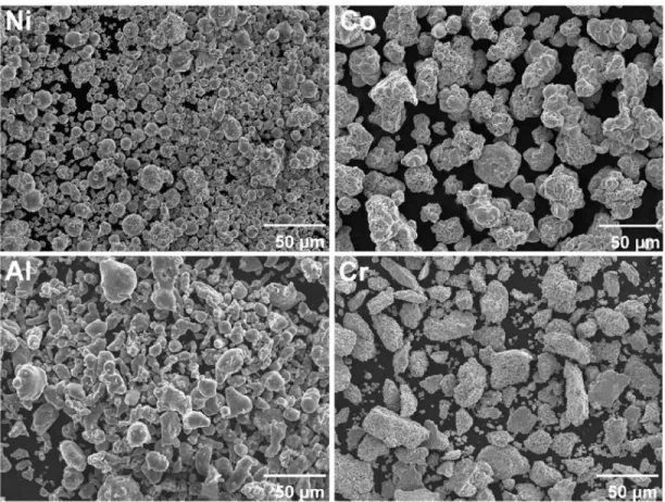
(6) https://cimav.repositorioinstitucional.mx/. media, mainly. Table 1 shows the nominal and chemical compositions from semiquantitative microanalyses on synthesized and commercial samples. The sample identification is included, and for synthesized samples the identification is related to the milling time. The presence of oxygen was not detected in milled products. This indicates that the oxidation level was very low. The most important variation was observed in aluminum content, this metal is the most ductile and probably the adhesion to milling media was stronger than in other metals. The AMDRY 997 (A997) alloy is a Ni-based alloy that is used in the aerospace industry as a BC in turbine blades [13]; [14] ; [15]. A997 constituents is similar to those selected in this work; the main difference with the studied alloys is the Tantalum and Yttrium content. Y is very reactive with oxygen; however, the addition of this element is due to the improvement of TGO scale adherence, increases of the creep strength of the TGO and the TBC life is extended when they are on bond coats with oxygen reactive elements [3]. On the contrary, Ta is used to increase the oxidation resistance; the use of both elements increases the life of BC. These elements are more expensive and difficult to handle in powder metallurgy process. This research aims to characterize MA'ed metallic alloys to determine if they can be potential candidates for use as BC, without the need to add a reactive element to form a high quality TGO. In powder metallurgy it is very important to know the nature of powder particles to understand the effect of processing. Scanning electron microscopy (SEM) is one of the most useful techniques for observing the discrete characteristics of metal powder particles. Fig. 1 shows the morphology and size of the elemental. 6.
(7) https://cimav.repositorioinstitucional.mx/. powders used in this work. As can be noticed, the morphology and size of the raw materials is quite different. Particle size is one of the most important characteristics in powder metallurgy. It can be determined by several techniques making often the assumption of a spherical particle shape. From a projected image of a rounded but irregular shape, six possible measures of particle size can be obtained, three based on projected dimensions and three based on equivalent spherical diameters [16]. Through SEM analysis the properties of shape, size, microstructure and chemistry of individual powder particles were determined. The particle size was obtained by measurements of the projected width of single particles observed in SE-SEM images. The Ni powders present the smallest and bimodal particle size ranging from 10–25 μm, while those of Co show an irregular morphology with larger particle size in the range of 30–50 μm. For instance, the powders of Al seem to exhibit a bimodal particle size distribution and rounded morphology. Finally, the morphology of Cr powders consists in flake-like particles with the largest particle size among the elemental powders.. 7.
(8) https://cimav.repositorioinstitucional.mx/. Fig. 2 shows the effect of milling time on the morphology and size, as well as the microstructure of the Ni60Co30Al10 and Ni60Co10Cr20Al10 powder alloys obtained by MA after 5 and 20 h of milling time. In general, the particles can be described with rounded but irregular shape, and a decrease is clear in the particle size for the two mixtures of powders when the milling is increased (Fig. 2a–d). After 5 h of milling, the MA'ed products exhibit a wide particle size distribution while 20 h of milling produces more equiaxial particles with a more uniform particle size distribution. The particle size is also reduced with the Cr addition; the quaternary alloy powders (< 50 μm) are smaller than those observed in the ternary alloy (> 50 μm) even when processed for a shorter milling time. This difference can be associated to the hardness of Cr powder (20 wt.%) in the quaternary alloy promoting 8.
(9) https://cimav.repositorioinstitucional.mx/. that fracture prevailed over cold weld process during mechanical alloying. Fig. 2e–h shows the effect of milling time on the microstructure of NiCoAl and NiCoCrAl MA'ed powders. For the shorter milling time (Fig. 2e and g), a quasi-lamellar structure is observed. Regions with different tonality denoting differences in composition are observed. This microstructure is typically observed in the early stages of MA with ductile components [11]. Further milling results in more uniform microstructures are observed in Fig. 2f and h, the lamellar structure is still not observed. It was also observed that the chemical distribution is more homogeneous after 20 h of milling.. 9.
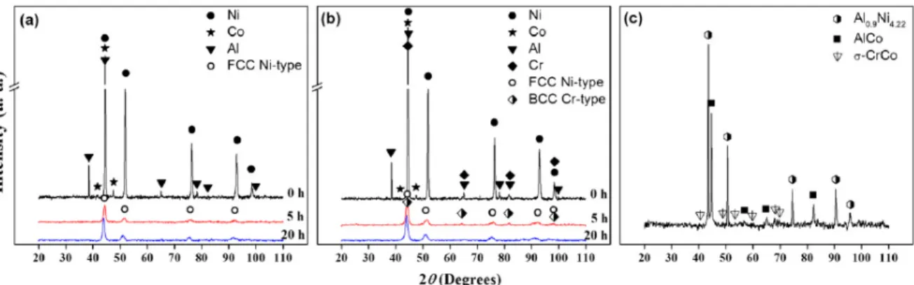
(10) https://cimav.repositorioinstitucional.mx/. AMDRY 997 is a NiCoCrAlTaY gas atomized alloy used as thermal spray coating with excellent high oxidation and hot corrosion resistance at high temperatures [17]. Cross section morphology and microstructure of commercial AMDRY powders are shown in Fig. 3. As can be seen, the particles of A997 exhibit a spherical morphology with sizes ranging from ~ 5–20 μm (Fig. 3a). Isolated porous with sizes lower than 1 μm is also detected. Furthermore, the cross section microstructure of this alloy shows a typical as-cast microstructure with gray-colored dendrite arms (Fig. 3b) and a continuous interdendritic phase with bright contrast. It is important to mention that these two phases identified by SEM and XRD were only observed in the commercial powders. Therefore, it can be seen that the milled powders present a higher microstructural homogeneity. Although the Y content in this alloy was not detected in a general EDS analysis (Table 1) due to its small amount in the alloy (less than 1 wt.%) , the presence of Y was detected in the interdendritic region of the polished cross-section of individual particles, as evidenced in EDS results of Fig. 3. Fig. 4 shows the XRD patterns of MA'ed and commercial powders. The Ni 60 Co 30 Al 10 and Ni 60 Co 10 Cr 20 Al 10 powder patterns are presented as a function of the milling time. In the synthesized samples (Fig. 4a and b), diffraction peaks corresponding to microcrystalline pure Ni, Co, Cr and Al are clearly visible in the unmilled samples (0 h of milling). After 5 h of MA, the intensity of Co, Cr and Al peaks decreases significantly remaining only the Ni characteristic peaks. Shortening and broadening as well as a slight shift to smaller 2θ values are observed in the Ni peaks, which suggest that: the alloying elements are dissolved into the Ni matrix. 10.
(11) https://cimav.repositorioinstitucional.mx/. inducing the formation of a solid solution, microstructure refinement and growing of the lattice parameter [18]. It is noteworthy that the crystal structure of Co powders is HCP in the un-milled condition (0 h of milling). Therefore, after milling, either the HCP structure transforms to FCC or Co is dissolved into the Ni matrix. As a result, the peak corresponding to Co HCP is no longer observed after 5 h of milling (see Fig. 4a and b). This can be explained by the reduction on the crystal size and accumulation of structural defects, as reported elsewhere [19] ; [20]. After 20 h of milling, the shortening of the Ni peaks and the displacement to lower angles are more evident indicating a variation on its lattice parameter [18]. The results of the lattice parameter and the crystal size calculated from XRD patterns of milledpowders by using Scherrer's formula [21] are shown in the Table 2. The crystal size of the FCC phases observed in the as-milled powder alloys is slightly reduced with the milling time; the effect of Cr addition on the crystal size is not clear to the overlap of the main peak of FCC Ni-type and BCC Cr-type phases. In the Ni 60 Co 30 Al 10 alloy the lattice constant of the single FCC Ni-type phase (a Ni = 0.352 nm) after 5 h of milling (0.352 nm) is smaller than that at 20 h of milling (0.356 nm). Co and Al atoms have much smaller concentration than Ni but higher atomic radius, the increase of the lattice parameter after milling indicates that solute atoms get dissolved into the Ni matrix. The Cr with a different crystalline structure and a higher atomic radius than Ni (FCC) produces in the Ni 60 Co 10 Cr 20 Al 10 alloy an increase in the lattice parameter of the Ni-type FCC phase from 0.355–0.357 nm at 5 and 20 h of milling, respectively. Also the peaks which correspond to a second BCC Cr-type phase were observed at. 11.
(12) https://cimav.repositorioinstitucional.mx/. 5 h of milling, and have the tendency to disappear as the milling time increases at 20 h, as a result of the Cr solute atoms being dissolved into the Ni matrix. Fig. 4c shows the XRD pattern of commercial AMDRY 997 powders. Sharp and high-intensity peaks are observed, without reflections of pure elements. The presence of Al 0.9 Ni 4.22 , AlCo and σ-CrCo microcrystalline phases was identified according to the ICDD PDF cards 00-050-1294, 00-029-0021 and 00-005-0706, respectively. The highest intensity peaks correspond to the Al 0.9 Ni 4.22 phase and the peaks corresponding to AlCo and σ-CrCo phases present the lowest intensity. The last one has been reported previously in some MCrAlY alloys [22]. Even though the constituents in commercial and milled powders is similar,. 12.
(13) https://cimav.repositorioinstitucional.mx/. the phases present in both conditions are completely different; this is because of the differences in the powders' chemical homogeneity, MA'ed powders are more homogeneous. Additionally, the MA'ed powders show a finer microstructure compared with the commercial powders due to the synthesis process, in accordance with the observed broadening in XRD patterns. 3.2. Sintered samples The SEM-BE images and SEM–EDS maps of the specimens sintered at 1100 °C are shown in Fig. 5. From this figure it is observed the high homogeneity in all specimens after sintering process. The Ni 60Co 30 Al 10 microstructure exhibits the formation of a single dark gray phase, while the Ni 60 Co 10 Cr 20 Al 10 alloy presents the formation of two phases, a Ni-rich (~ 65 wt.% Ni) solid solution phase and a Cr-rich (~ 74 wt.% Cr) phase. Microanalyses showed that Cr-rich phase has no nickel content. In accord with SEM–EDS mappings, the milling time does not have a significant effect on the microstructure after sintering. On the other hand, the commercial alloy (A997) after sintering exhibits a coarsened dendritic microstructure with two main phases a dark Al-rich phase, and a gray Cr-rich phase, in addition the presence of a small bright Ta-rich located in the grain boundaries between the two main phases is observed.. 13.
(14) https://cimav.repositorioinstitucional.mx/. Yttrium content was not detected. The chemical distribution after sintering is more homogeneous in the MA'ed samples. The XRD patterns of the sintered specimens are shown in Fig. 6. For the MA'ed samples after sintering (Fig. 6a), the diffraction peaks corresponding to a FCC phase with a lattice parameter of 0.355 nm, which is close to pure Ni (0.352 nm) is presented in all alloys. However, samples containing Cr (5B and 20B) have shown a shifting to lower angles, indicating an increment in the lattice parameter [18]. In accord with Fig. 5, it is expected that Al, Co and Cr are dissolved into the Ni matrix. Additionally, the presence of a second phase was identified as a. 14.
(15) https://cimav.repositorioinstitucional.mx/. tetragonal AlCr 2 phase (ICDD card 00-029-0016) in the Ni 60 Co 10 Cr 20 Al 10 alloy; this phase is due to the remnant Cr that was not dissolved into the Ni matrix. For the commercial alloy, after sintering process the same diffraction peaks than those observed in the powder condition are observed, the same phases presented in Fig. 4c were identified, without significant structural changes. 3.3. Oxidation behavior of bulk samples The consolidated samples were subjected to thermal oxidation at 1000 °C for different times. After oxidation tests, the samples were examined by XRD technique. From the initial oxidation results at 1 h, considerable structural changes were not observed in comparison to the sintered samples for the two studied compositions (Fig. 7a). However, after 3 h of oxidation, α-Al 2 O 3 phase (ICDD card 00-005-0712) was identified in the surface of the Ni 60 Co 30 Al 10 alloy, while β-Al 2 O 3 and Cr 2 O 3 phases were identified in the Ni 60 Co 10 Cr 20 Al 10 alloy, according to the ICDD cards 00-010-0414 and 00-001-1294, respectively (Fig 7b). For the commercial alloy, even after 3 h of oxidation, the oxide scale formation was not clearly detected by XRD technique. Only the diffraction peaks corresponding to the main phase (Al 0.9 Ni 4.22 ) are observed. For this reason, the polished cross sections of the oxidized samples were examined by scanning electron microscopy.. 15.
(16) https://cimav.repositorioinstitucional.mx/. The oxide scales formed after oxidation at 1000 °C for 3 h are shown in the EDS maps of Fig. 8. The ternary alloy presents a single-phase solid solution microstructure and exhibits a homogeneous distribution of Ni, Co and Al, as well as, the formation of an aluminum oxide scale in the surface of the sample. This oxide scale presents a thickness around 1 μm. Apparently for this alloy, milling time does not have an effect after oxidation, both samples present similar microstructure and similar characteristics of the oxide scale. It is known that the presence of a significant amount of Cr and oxidizing atmosphere, promotes the formation of coatings with excellent corrosion resistance combined with good oxidation resistance, accelerating the oxide scale formation rate [23]. In the quaternary alloy, the Cr induces to the formation of a multiphase microstructure, solid solution phase as a matrix containing all the elements, and two discontinuous phases, an Al–Ni-rich phase observed as dark regions and a Cr-rich phase observed as gray regions. For 16.
(17) https://cimav.repositorioinstitucional.mx/. this alloy, the milling time has a significant effect on the microstructure after the oxidation test, as evidenced in the thickness of the oxide scale and in the volume fraction of the discontinuous phases. The alloy system milled during 20 h exhibits a more homogeneous microstructure than that milled for 5 h. A greater milling time for the Ni 60 Co 10 Cr 20 Al 10 alloy results in a slower oxide scale growth rate. Additionally, longer milling times promote the formation of chromium oxide together with the more stable aluminum oxide. This observations support the XRD results presented in Fig. 7b. With respect to the commercial alloy, after performing the oxidation test in the same conditions, an aluminum oxide scale formation is observed (Fig. 8). In comparison to the Ni 60 Co 10 Cr 20 Al 10 alloy milled during 20 h, the aluminum oxide scale growth rate is higher; and the chromium oxide is not present. Besides, the chemical distribution is more homogenous in the sample prepared by mechanical alloying. 3.4. Microhardness Fig. 9 shows the microhardness results of powders and bulk samples (sintered and oxidized conditions). For comparison purposes, the results from the commercial alloy (A997) are also presented. It can be clearly seen that the mechanically alloyed samples have higher hardness compared with the commercial alloy. Also, it is observed that Cr content and milling time have a significant and positive effect on the microhardness. It is observed that the increment in hardness by milling time variations is most important than that observed by Cr additions. The Ni 60 Co 10 Cr 20 Al 10 alloy milled during 20 h was the sample with the highest hardness in all conditions (as-milled, as-sintered and oxidized conditions). There are several. 17.
(18) https://cimav.repositorioinstitucional.mx/. differences among commercial sample and milled powders: microstructure and powder morphology, present phases, crystal size, chemical homogeneity and hardness, being the most important the high homogeneity and the crystal size in nanoscale range observed in MA'ed products. These characteristics have a direct effect on the hardness. This can be explained by the grain and microstructure refinement. The hardening effect due to the Cr addition and mechanical alloying observed in milled samples remains after the sintering process; the samples milled during 20 h exhibit a major hardness than those milled for 5 h, and the alloys with Cr content have a greater hardness than the Ni 60 Co 30 Al 10 alloys. However, the Cr effect on hardness is more important than mechanical alloying effect after sintering process. The Ni 60 Co 30 Al 10 sample MA'ed for 20 h is harder than the Ni 60 Co 10 Cr 20 Al 10 sample MA'ed for 5 h, while after sintering the alloys containing Cr exhibit greater hardness regardless of milling time. This effect is probably due to the formation of a Cr-rich phase, identified as a tetragonal AlCr 2 phase, which could provide an additional strengthening in the Ni 60 Co 10 Cr 20 Al 10. 18.
(19) https://cimav.repositorioinstitucional.mx/. sintered samples (5B and 20B), since some studies have reported the reinforcement effect of the AlCr 2 phase in metal matrix composites [24]. During heating treatments at elevated temperatures it is common the softening of work hardened materials [25]. For this reason, the oxidized samples were also tested by Vickers microhardness technique to determine the hardness behavior as a function of the microstructural evolution after thermal oxidation at high temperature. In the MCrAlX alloys, the function of Cr and Al is to provide a reservoir that continually replenishes in the oxide scale, hence an increase of surface roughness. 19.
(20) https://cimav.repositorioinstitucional.mx/. after thermal oxidation (porosity) is common [23], this phenomenon is clearly observed in the SEM image of Ni 60 Co 30 Al 10 sample milled for 5 h, where porosity in microstructure is evident (Fig. 8). The phenomenon of porosity is reflected in the decrease of microhardness after oxidation (Fig. 9). The selection of an appropriate alloy for use in oxidation resistance at high temperature applications must be based on the structure, microstructure and properties of the alloy, characteristics that depend on its chemical composition [26]. In the MCrAlY alloys the presence of Cr and Y improves the oxidation resistance by increasing the Al activity and the formation of a protective oxide scale [27]. According to the XRD and SEM analysis, the studied alloys exhibited the formation of aluminum oxide scale under thermal oxidation in air.. 20.
(21) https://cimav.repositorioinstitucional.mx/. 4. Conclusions Mechanical alloying and conventional sintering were employed to produce two Ni-based alloys. The possibility to use high temperature NiCrCoAl alloys without Yttrium content for bond coat applications was evaluated with the synthesis and characterization of the investigated Ni 60 Co 30 Al 10 and Ni 60 Co 10 Cr 20 Al 10 alloys. The main conclusions were as follows: 1. In comparison to a commercial alloy produced by atomization, the synthesized powder alloys showed irregular morphology, higher microstructural homogeneity and enhanced hardness, due to the effect induced by the mechanical alloying process. 2. After sintering, the effect of Cr addition was observed with the formation of Cr-rich phases and an increase in microhardness. 3. After thermal oxidation the oxide products formed on the surface of consolidated samples were aluminum oxide for the Ni 60 Co 30 Al 10 alloys, and chromium oxide together with aluminum oxide for the Ni 60 Co 10 Cr 20 Al 10 alloy. 4. The formation of a homogeneous and continuous aluminum and chromium oxide scales make these mechanically alloyed powders potential candidates for high temperature applications as protective bond coats.. Acknowledgments This research was supported by CONACYT-Red Temática de Nanociencias y Nanotecnología and Red Temática de Ciencia y Tecnología Espaciales (0124623, 0124891, 0170224 and 0170617). Thanks to W. Antunez-Flores, and K. Campos-Venegas for their technical. 21.
(22) https://cimav.repositorioinstitucional.mx/. assistance.. References [1]. P. Richer, M. Yandouzi, L. Beauvais, B. Jodoin, Oxidation behaviour of. CoNiCrAlY bond coats produced by plasma, HVOF and cold gas dynamic spraying, Surf. Coat. Technol. 204 (2010) 3962–3974. [2]. R.C. Reed, The Superalloys: Fundamentals and Applications,. Cambridge University Press, 2006. [3]. S. Bose, High Temperature Coatings, Elsevier Science, 2011.. [4]. M. Daroonparvar, M.A.M. Yajid, N.M. Yusof, H.R. Bakhsheshi-Rad, Z.. Valefi,E. Hamzah, Effect of Y2O3 stabilized ZrO2 coating with tri-model structure on bi-layered thermally grown oxide evolution in nanothermal barrier coating systems at elevated temperatures, J. Rare Earths 32 (2014) 57–77. [5]. H. Chen, T.H. Hyde, K.T. Voisey, D.G. McCartney, Application of small. punch creep testing to a thermally sprayed CoNiCrAlY bond coat, Mater. Sci. Eng. A 585 (2013) 205–213. [6]. A.C. Karaoglanli, E. Altuncu, I. Ozdemir, A. Turk, F. Ustel, Structure. and durability evalu-ation of YSZ + Al2O3 composite TBCs with APS and HVOF bond coats under thermal cycling conditions, Surf. Coat. Technol. 205 (Supplement 2) (2011) S369–S373. [7]. X. Zhao, J. Liu, D.S. Rickerby, R.J. Jones, P. Xiao, Evolution of. interfacial toughness of a thermal barrier system with a Pt-diffused γ/γ′ bond coat, Acta Mater. 59 (2011) 6401–6411.. 22.
(23) https://cimav.repositorioinstitucional.mx/. [8]. Y.J. Han, F.X. Ye, G.X. Lu, C. Liu, L.J. Hao, Residual stress evolution. of thermally grown oxide in thermal barrier coatings deposited onto nickel-base superalloy and iron-base alloy with thermal exposure ageing, J. Alloys Compd. 584 (2014) 19–27. [9]. K. Yuan, R. Eriksson, R. Lin Peng, X.-H. Li, S. Johansson, Y.-D. Wang,. Modeling of microstructural evolution and lifetime prediction of MCrAlY coatings on nickel based superalloys during high temperature oxidation, Surf. Coat. Technol. 232 (2013) 204–215. [10]. E.P. Busso, H.E. Evans, Z.Q. Qian, M.P. Taylor, Effects of breakaway. oxidation on local stresses in thermal barrier coatings, Acta Mater. 58 (2010) 1242– 1251. [11]. C. Suryanarayana, Mechanical alloying and milling, Prog. Mater. Sci.. 46 (2001) 1–184. [12]. W. Gao, Z. Li, Nano-structured alloy and composite coatings for high. temperature applications, Mater. Res. 7 (2004) 175–182. [13]. A. Vande Put, M.-C. Lafont, D. Oquab, A. Raffaitin, D. Monceau,. Effect of modification by Pt and manufacturing processes on the microstructure of two NiCoCrAlYTa bond coatings intended for thermal barrier system applications, Surf. Coat. Technol. 205 (2010) 717–727. [14]. M. Goral, S. Kotowski, A. Nowotnik, M. Pytel, M. Drajewicz, J.. Sieniawski, PS-PVD deposition of thermal barrier coatings, Surf. Coat. Technol. 237 (2013) 51–55. [15]. X.-f. Zhang, K.-s. Zhou, X. Wei, B.-y. Chen, J.-b. Song, M. Liu, In situ. 23.
(24) https://cimav.repositorioinstitucional.mx/. synthesis of α-alumina layer at top yttrium-stabilized zirconia thermal barrier coatings for oxygen barrier, Ceram. Int. 40 (2014) 12703–12708. [16]. R.M. German, Powder metallurgy science, Metal Powder Industries. Federation1994. [17]. H. Mei, Y. Liu, L. Cheng, L. Zhang, Corrosion mechanism of a. NiCoCrAlTaY coated Mar-M247 superalloy in molten salt vapour, Corros. Sci. 55 (2012) 201–204. [18]. B.D. Cullity, S.R. Stock, Elements of X-ray Diffraction, Prentice Hall,. [19]. S. Ram, Allotropic phase transformations in HCP, FCC and BCC. 2001.. metastable structures in Co-nanoparticles, Mater. Sci. Eng. A 304–306 (2001) 923– 927. [20]. J.Y. Huang, Y.K. Wu, H.Q. Ye, Allotropic transformation of cobalt. induced by ball milling, Acta Mater. 44 (1996) 1201–1209. [21]. J.I. Langford, A.J.C. Wilson, Scherrer after sixty years: a survey and. some new results in the determination of crystallite size, J. Appl. Crystallogr. 11 (1978) 102–113. [22]. W.G. Sloof, T.J. Nijdam, On the high-temperature oxidation of MCrAlY. coatings, Int. J. Mater. Res. 100 (2009) 1318–1330. [23]. J.E. Pope, Rules of Thumb for Mechanical Engineers, Elsevier. Science, 1996. [24]. L. Nie, M. Pang, H. Wang, Y. Zhan, First-principles investigations on. the crystal, electronic structure and mechanical properties of AlCr2 compound at. 24.
(25) https://cimav.repositorioinstitucional.mx/. varying pressures, Comput. Mater. Sci. 61 (2012) 140–144. [25]. E.M. Francis, B.M.B. Grant, J.Q.d. Fonseca, P.J. Phillips, M.J. Mills,. M.R. Daymond, M. Preuss, High-temperature deformation mechanisms in a polycrystalline nickel-base superalloy studied by neutron diffraction and electron microscopy, Acta Mater. 74 (2014) 18–29. [26]. Y. Saito, B. Önay, T. Maruyama, High Temperature Corrosion of. Advanced Materials and Protective Coatings, Elsevier Science, 2012. [27]. W. Gissler, H.A. Jehn, Advanced Techniques for Surface Engineering,. Springer, 1992.. 25.
(26)
Figure
Documento similar