Theory and principles of nickel titanium shape memory alloy as smart material on the design of cardiovascular stents
94
0
0
Texto completo
(2) INSTITUTO TECNOLOGICO Y DE ESTUDIOS SUPERIORES DE MONTERREY CAMPUS MONTERREY DIVISION DE INGENIERIA Y ARQUITECTURA PROGRAMA DE GRADUADOS EN INGENIERIA. Los miembros del Comité de Tesis recomendamos que la presente Tesis del Ing. Manuel Ignacio Varela Jiménez sea aceptada como requisito parcial para obtener el grado académico de Maestro en Ciencias con especialidad en: SISTEMAS DE MANUFACTURA. Comité de Tesis. __________________________________ Dr. Jorge Armando Cortés Ramírez Asesor. __________________________________ Dr. Sergio Gallegos Cázares Sinodal. __________________________________ Dr. Lucio Florez Calderón Sinodal. APROBADO. _______________________________________ Dr. Francisco Román Ángel - Bello Acosta Director del Programa de Graduados en Ingeniería. Diciembre 2007.
(3) DEDICATED TO. A mis padres, Dr. Ignacio Varela Maldonado y Dra. Lourdes Jiménez Guzmán Son el mejor regalo que me ha dado la vida, gracias por su inmenso amor y cariño, por apoyarme siempre para alcanzar mis objetivos, mantenerme motivado para ser una mejor persona y no dejarme dar por vencido.. A mi hermano Ricardo Emilio, has sido por siempre mi gran compañero y amigo. Gracias por tu cariño y compañía; con tu dedicación y esfuerzo diario has sido un gran ejemplo para mí.. A mi hermana Rosa Ofelia. Soy muy dichoso al contar con alguien tan linda como tú. Con tu gran alegría y espíritu me has impulsado a seguir adelante y no dejarme vencer.. A mi tío Isi y mi tía Bety, a Isi y a Pol: mi segunda familia. Su cariño y enseñanzas forman parte de mí, y han sido fundamentales para llevarme a terminar esta etapa de mi vida. Gracias por todo.. A mi abuelita Rosita y mi abue Ofelia. Muchas gracias por su amor, cariño y oraciones. Por darme a un padre y una madre tan maravillosos.. Gracias familias Varela Maldonado y Jiménez Guzmán. Ustedes han sido mi gran motivación para lograr este trabajo. Con todo mi amor y cariño hoy se los entrego.. I.
(4) ACKNOWLEDGEMENTS A DIOS, por darme a mi familia y amigos; por no dejarme vencer y darme la sabiduría y fuerza de voluntad para lograr sacar adelante este trabajo. Al Dr. Jorge Armando Cortés Ramírez. Muchas gracias por creer en mí y darme todo su apoyo y confianza, le agradezco mucho sus consejos, pero sobre todo, su amistad. Al Dr. Sergio Gallegos y al Dr. Lucio Florez. Gracias por su confianza, por todo su apoyo y consejos para mejorar este trabajo. Al Dr. David Guerra Zubiaga, por haberme impulsado y motivado a estudiar un posgrado. Muchas gracias por todos sus consejos y apoyo. A mis compañeros asistentes en la Cátedra de Bioingeniería: Ruth Oseki Valdés y Josué Guzmán. Aprendí mucho de ustedes. Muchas gracias por su amistad. Finalmente trabajando en equipo y apoyándonos en momentos difíciles, logramos cumplir nuestro objetivo. Al Ing. Pablo Vargas y al Ing. Rogelio de la Garza, por sus consejos y sugerencias para la realización de experimentos. A Luís Guillermo Loo, muchísimas gracias por tu esfuerzo y paciencia. Tu apoyo en los experimentos ha sido fundamental para hacer este trabajo. Al Dr. Juan Quintanilla y la Enf. Lidia Alvarez, por compartir sus conocimientos y experiencia sobre el uso de stents cardiovasculares. To Dr. Takaomi Kobayashi, Dr. Yoshiro Ito and Dr. Rie Tanabe, for support my research work about laser technology at Nagaoka University of Technology. A la Cátedra de Investigación en Dispositivos Biomédicos (Bioingeniería) por el apoyo económico para la realización de mis estudios de maestría. A la Ing. Elizabeth Vargas por facilitarme el uso del Laboratorio de Materiales Industriales, al Ing. Gabriel Soto por su ayuda para la realización de pruebas mecánicas. A todos mis tíos y mis queridos primos. Me es imposible citarlos a todos en este espacio… de todo corazón les agradezco su apoyo y los bellos momentos que hemos pasado juntos. Han sido mi motivación en los momentos difíciles. A mis compañeros y amigos del CIDyT y maestría: Edgar Ríos, Edgar Raygoza, Luís Hernández, Gaby Barba, Graciela Sepúlveda, Iraís Herás, Roberto Delgado, Roberto Rosas, Ricardo Camacho, Marcopolo Ramos, José Luís Serrano, Mauricio Hincapié, Pedro García y Luís Martello. A mis amigos Fernando Olea, Rómulo Escamilla, Nino Quintanilla, Rubén del Pozo, José Pizaña, David Carillo, Eleazar Santos, Rosa Elisa Martínez, Alma Robles, Alonso Arellano, Citlalli Hernández, Rociohelí Obregón, Ana Laura Jáuregui, Luz Eunice Ochoa, José Luís Martínez, por su amistad y confianza en estos últimos años de mi vida. A mis amigos latinos en la Universidad de Nagaoka: Fernando, Oscar, Marielena, David Murcia, David Lanza, Dai, Aline y Yu. Gracias a su apoyo y amistad logré sacar adelante mi investigación.. II.
(5) SUMMARY. The changes in manufacturing environment are characterized by aggressive competition on a global scale and rapid changes in process technology. The development of ‘smart’ materials and the need of systems that can be readily reconfigured for a wide range of requirements have become necessary for the future.. Nickel – Titanium alloy is a ‘smart’ material with shape memory effect, dominated by a transition between the austenite phase and the martensite structure. The chemical composition and the heat treatment have a significant effect on the transformation temperature of the material; in order to take advantage of the properties of NiTi control of this temperature is essential.. One of the applications of NiTi is stents, taking advantage of the NiTi biocompatibility, large recoverable deformation, good fatigue life, superelastic and shape memory properties around body temperature, allowing the development of self-expanding stents.. This works has as purpose the development of a constitutive model of NiTi phase transformation from martensite to austenite and the effect of heat treatment on the setting of transformation temperature, to be applied in the design, numerical simulation and laser manufacture of self-expandable stents.. Also, considering that the improvement of stents designs and operation by the use of smaller dimensions, functional materials or polymers requires research about modern surface coatings and stent laser manufacturing methods is required, this research also intends to establish the state of art about stents materials, surface coatings and manufacture.. III.
(6) INDEX DEDICATED TO ……………………………………………………………… ACKNOWLEDGEMENTS …………………………………………………… SUMMARY …………………………………………………………………… INDEX…………………………………………………………………………. LIST OF FIGURES …………………………………………………………… LIST OF TABLES ……………………………………………………………. LIST OF SYMBOLS. I II III IV VI VIII IX. PART I. THEORY Chapter 1. INTRODUCTION ...……………………………………………… 1.1. Background ……………………………………………………... 1.2. Research Justification …………………………………………... 1.3. Objectives……………………………………………………….. 1.4. Methodology ……………………………………………………. 1.5. References ……………………………………………………….. 10 10 17 18 18 20. Chapter 2. MEMORY EFFECT THEORY AND CONSTITUTIVE MODEL DEVELOPMENT FOR MARTENSITE TO AUSTENITE PHASE TRANSFORMATION IN NICKEL – TITANIUM ALLOY 22 2.1. Background ……………………………………………………... 22 2.2. Experimental Work ……… …………………………………….. 31 2.3. Transformation Temperature Setting ………………………….... 32 2.4. Thermo-Mechanical Test ………………………………………… 34 2.5. Constitutive Relation During Temperature Increase And Return Of Achieved Strain ……………………………………… 38 2.6. Chapter Remarks ………………………………………………... 43 2.7. References ………………………………………………………. 44 PART II. APPLICATION Chapter 3. PRINCIPLES AND DESIGN AND MANUFACTURE FOR NICKEL – TITANIUM ALLOY CARDIOVASCULAR STENTS …. 3.1. Background ……………………………………………………… 3.2. Stents Materials and Surface Coatings …………………………. 3.2.1 Metals and Polymers ……………………………………. 3.2.2. Stents Surface Coatings …………………………………. 3.2.3. Drug Eluting Stents (DES) ……………………………… 3.3. Stents Manufacturing …………………………………………… 3.3.1. Laser Cutting Fundamentals ……………………………. 3.3.2. Laser Cutting Parameters and Its Influence on Process Quality ……………………………………… 3.4. Stents Designs…………………………………………………… 3.5. Chapter Remarks…………………………………………………. 3.6. References ………………………………………………………... 45 45 51 51 55 57 59 59 65 74 80 83. PART III. RESULTS AND CONCLUSIONS Chapter 4. CONCLUSIONS AND FURTHER WORK …………………….. 81 4.1 Conclusions ………………………………………………………. 81 4.2 Further Work ……………………………………………………. 81. IV.
(7) APPENDIX …………………………………………………………………….. A.1 Laser Background ……………………………………………….. A.2 Laser Fundamentals ……………………………………………... A.3 Laser Components ………………………………………………. A.4. Laser Types ……………………………………………………… A.5. References ………………………………………………………... V. 88 88 89 90 91 92.
(8) LIST OF FIGURES. Fig. 1-1. Phase Diagram for Nickel – Titanium Alloy. Fig. 1-2. TTT Diagram for Nickel – Titanium Alloy. Fig. 1-3. Microstructural Evolution of Nickel – Titanium Alloy. Fig. 1-4. Martensite Volume Fraction vs Strain at Different Temperatures. Fig. 1-5. Typical Metallic Stent. Fig. 1-6. Stenting Process. Fig. 1-7. Stent in a Hand. Fig. 1-8. Hollow Cylindrical Mesh Forming a Stent. Fig. 2-1. Typical Stress-Strain-Temperature behavior of NiTi Fig. 2-2. Martensite Fraction Dependence of Transformation Temperatures. Fig. 2-3. Relation between Temperature and Transformation Fig. 2-4. Strain change because of the Detwinned Martensite – Austenite transformation Fig. 2-5. Plastic Strain Induce Detwinned Martensite Formation from point A to point B Fig. 2-6. NiTi Ribbon used for experimental work Fig. 2-7. Heat Treatment Process for setting a different As Fig. 2-8. Metallographic analysis of NiTi specimens Fig. 2-9. Stress – Strain Curve for NiTi samples during mechanical test. Fig. 2-10. Experimental work on NiTi by heating and measuring length reduction. Fig. 2-11. NiTi volume reduction during heating and volume increase during cooling ‘R’. Fig. 2-12. Relation of Experimental Austenite Volume Fraction and Temperature. Fig. 2-13. Characteristic Temperature Tc vs Heat Treatment Time Fig. 2-14. B constant vs Heat Treatment Time Fig. 2-15. Austenite Volume Fraction estimated by constitutive model. Fig. 2-16. Stress for the austenite and detwinned martensite. Fig. 2-17. Constants as a function of temperature for twinned martensite and austenite Fig. 2-18. Stress-Strain relation due to temperature Fig. 3-1. ‘Atlas’™ stent Fig. 3-2. ‘Smart Control’™ stent. Fig. 3-3. Micrograph showing cut width of la stent manufactured by laser.. VI.
(9) Fig. 3-4. Schematic of Laser Cutting Machine. Fig. 3-5. Heat Affected Zone in Laser Cutting of Titanium Alloy. Fig. 3-6. Stent coated with heterologous tissue. Fig. 3–7. Laser Cutting Elements. Fig. 3-8. Laser Micromachining with Long Pulse Laser. Fig. 3-9. Striation zones created by laser in cut surface. Fig. 3-10. Roffin™ ‘StarCut Tube’™. Fig. 3-11. Laser Micromachining with Ultrafast Pulses Laser. Fig. 3-12. Laser Experiments Optic Tools. Fig. 3-13. Variable Neutral Filter Fig. 3-15. Tungsten Carbide Femtosecond Laser Ablation Experiment Arrangement. Fig. 3-16. Optical micrograph of irradiated PC. Fig. 3-17. Scanning Electron Microscope images of PCL surface ablated by femtosecond laser Fig. 3-18. Laser cutting defects on steel by bad selection of scan speed. Fig. 3-19. Steel cut by laser using Oxygen as assistant gas, which produces colored surfaces. Fig. 3-20. Comparison of Titanium alloy laser cutting with different assistant gas. Fig. 3-21. Tubular Mesh Stent. Fig. 3-22. Slotted Tube Stent. Fig. 3-23. Coil Stent Fig. 3.24. Popular drug eluting balloon-expandable stents. Fig. 3.25. SmartControl™ stent.. VII.
(10) LIST OF TABLES Table. 2-1.. Transformation Temperature for Nickel – Titanium Alloy Sample.. Table. 2-2.. Chemical Composition of Nickel – Titanium Alloy Sample.. Table. 2-3.. Temperatures and Times of Heat Treatment for each NiTi specimen.. Table. 3-1.. Mechanical Properties of Metals used in Stents. Table. 3-2.. Materials with ideal characteristics for coronary stent applications. Table. 3-3.. Some commercial stents approved by the FDA. VIII.
(11) LIST OF SYMBOLS. Ni. Nickel. Ti. Titanium. NiTi. Nickel – Titanium Alloy. C. Carbon. Fe. Iron. Cr. Chrome. Cu. Copper. Co. Cobalt. Mg. Magnesium. Co-Cr. Cobalt - Chrome Alloy. Pt–Ir. Platinum–Iridium Alloy. SS. Stainless Steel. TTT. Temperature-Time-Transformation. CAD. Computer Aided Design. FEM. Finite Element Method. Tx. Temperature of NiTi. As. Temperature at which martensite to austenite transformation starts.. Af. Temperature at which austenite transformation finishes.. Ms. Temperature at which austenite starts to transform to twined martensite.. Mf. Temperature, at which twined martensite transformation finishes.. TTR. Transformation Temperature. H. Hysteresis. SMA. Shape Memory Alloy. SME. Shape Memory Effect. Mm3. Cubic millimeters. O. Celsius Grade. σt. Strength of NiTi Alloy.. C. σγ. Strength of austenitic structure.. σα’’. Strength of austenitic structure.. IX.
(12) Vfγ. Volumetric Fraction of austenitic structure. Vfα. Volumetric Fraction of martensitic structure. Tc. Characteristic Temperature. B. NiTi constant. t. Heat Treatment Duration Time. kγ , n. Austenite microstructure constants. kα’’, n’’. Martensite microstructure constants. ε. Material strain. HAZ. Heat Affected Zone. CABG. Coronary Artery Bypass Grafting. PCTA. Percutaneous Transluminal Coronary Balloon Angioplasty. DES. Drug Eluting Stents. MRI. Magnetic Resonance Imaging. Nd-YAG. Neodymium - Yttrium Aluminum Garnet. CNC. Computer and Numerically Controlled. ND. Neutral Density. VND. Variable Neutral Filter. CO2. Carbon Dioxide. ATF. Ablation Threshold Fluence.
(13) Chapter 1. Introduction. PART I. THEORY 1.. INTRODUCTION. 1.1.. BACKGROUND. The changes in manufacturing environment are characterized by aggressive competition on a global scale and rapid changes in process technology. In United States; industry, government and other institutions have identified, materials and manufacturing trends for 2020. An important point in this vision is the development of ‘smart’ materials which have properties to self-repair, actuate and transduce; and the need of innovative processes to design and manufacture new materials and components along with adaptable, integrated equipment, processes, and systems that can be readily reconfigured for a wide range of requirements [1.1].. Shape memory alloys are considered ‘smart’ materials, such as Nickel (Ni) – Titanium (Ti) alloy (NiTi), also known as Nitinol™. The shape memory effect is a controlled transition between the austenite phase and the martensite structure [1.2]. The atomic array of the martensite structure has a higher volume than the atomic array of the austenite phase; thus, the atomic repositioning and volume contraction are the causes of the “memory” of the material [1.3].. It is considered that the chemical composition and the metallurgical treatment have a significant effect on the temperature at which the material starts its phase transformation returning to its shape memory, known as transformation temperature; thus, to take advantage of the properties of NiTi control of this temperature is essential. In general, increasing the Ti content leads to an increase in the transformation temperature [1.4].. The phase diagram of NiTi in Fig. 1-1 shows that TiNi phase is stable only at temperatures above 630°C. This diagram and the Temperature-Time-Transformation (TTT) diagram (shown in Fig. 1-2), allow determining the phase transformations with isothermal holds outside the TiNi single phase field depending of the chemical composition. The TTT diagram suggests. 10. Manuel Ignacio Varela Jiménez.
(14) Chapter 1. Introduction. that the transformation temperature of NiTi can change. Thus, manipulation of the transformation temperature is possible [1.4].. Fig. 1-1. Phase Diagram for NiTi [1.4]. Fig. 1-2. TTT Diagram for NiTi with a specific chemical composition, showing Transformation Temperatures Change according to Thermal Treatment [1.4].. 11. Manuel Ignacio Varela Jiménez.
(15) Chapter 1. Introduction. As shown in Fig. 1-3, microstructure transformation from austenite to martensite may be induced by plastic strain [1.5].. Fig. 1-3. Microstructural Evolution of NiTi along its Stress-Strain curve, where: A) Austenite, B) 50% Austenite 50% Martensite, C) 100% Martensite [1.5]. Up to day, several studies have been made about the NiTi, but there is a lack in the development of the numerical analysis of the phenomenology of the material, because there are not enough accurate models according to the stress, strain, and the temperature behavior of the NiTi [1.5].. In previous work [1.3, 1.5] a constitutive model for NiTi which describes stress of the material according to the stress of every microstructure has been established. It is also composed by an. 12. Manuel Ignacio Varela Jiménez.
(16) Chapter 1. Introduction. additional model that represents the phase transformation from austenite to martensite due to strain, as shown in Fig. 1-4. 1 0.9 0.8 0.7 0.6. V fm. Vfm 0.5. ε B = 1 + QT A e ⋅ . −1. 0.4 0.3. 25°C. 0.2. 40°C. 0.1. 55°C. 0 0. 0.02. 0.04. ε. 0.06. 0.08. 0.1. Fig. 1-4. Martensite Volume Fraction vs Strain at different temperatures and its constitutive model [1.5] In order to complement previous work, it is necessary to develop an additional model of the martensite volume fraction cycle due to strain and temperature by establishing a similar constitutive model for the return from martensite to austenite according to the martensite dissolution.. One of the applications of a “smart” material, specifically for NiTi, is in medical surgery and human implants; where fine instruments, such a stents (shown in Fig 1-5) are used. The applications make use of the NiTi biocompatibility, large recoverable deformation, good fatigue life, superelastic and shape memory properties around body temperature [1.6], allowing the development of self-expanding stents [1.7].. 13. Manuel Ignacio Varela Jiménez.
(17) Chapter 1. Introduction. As shown in Fig. 1-6, stents are often used as treatment for atherosclerosis; it is specific to the arteries and is common reason for death in western countries [1.8].. Fig. 1-5. Typical Metallic Stent [1.9]. A stent, shown in Fig.1-7, is a miniature device typically made from a hollow cylindrical tube with a patterned slit structure which forms a cylindrical wire mesh, shown in Fig. 1.8, which is used to support arterial walls to alleviate the blockage of arteries due to plaque [1.10]; a fatty substance formed mainly by cholesterol, which accumulates and slowly becomes thicker and influences the mobility of blood flow [1.8]. If it is untreated, blood flow to an organ is reduced or even an artery is blocked [1.8, 1.11], may causing an infarction [1.9].. Fig. 1-6. Stenting Process, (a) Fatty layer accumulates at and near the artery wall, (b) Catheter contains the balloon which inflates and expands the stent, (c) Fatty layer is pushed against the wall after balloon deflation and catheter is removed [1.12]. 14. Manuel Ignacio Varela Jiménez.
(18) Chapter 1. Introduction. Fig. 1-7. Stent in a Hand [1.13]. The diameter is in a range of 2-4 mm and its length in a range of 15-20 mm.. Fig. 1-8. Hollow Cylindrical Mesh Forming a Stent [1.9]. The wire in section A-A has a diameter of 100 µm approximately Although stenting has become the principal treatment for atherosclerosis, the reocclusion of the treated artery, known as restenosis, may exit. This problem has become the main bottle neck to the development of stent technique and extensive work has been devoted to face it, such as the development of biodegradable stents and drug coated stents [1.14]. In fact, many stents designs are available; however, no single design incorporates all the characteristics of an ideal stent [1.15]. Because of this situation, different types of metal have been used; the majority of stents are composed of 316L stainless steel or NiTi mesh tubes [1.7].. Shape Memory Effect gives NiTi the ability to return to a predetermined shape when heated [1.9]. This property allows the development of self-expanding stents, which can be manufactured with a diameter larger than that of the target vessel and a phase transformation temperature around 30oC. Then, they can be crimped at, or below, room temperature and. 15. Manuel Ignacio Varela Jiménez.
(19) Chapter 1. Introduction. placed in a delivery system. At the target area in the vessel, the stent is released and expands at body temperature until it hits the artery wall and conforms to it [1.7].. The general trend of stenting is towards self-expandable NiTi-based stents. The carotid artery stents and the stent for abdominal aortic aneurysms have been proved to be efficient and technically successful. Intracoronary and peripheral vascular NiTi stenting also seems to be increasing. Their benefits include good radial expansion capabilities and flexibility NiTi stents are also used in gastroenterology where self-expanding stents for esophageal strictures and the palliation of malignomas have been studied, these stents are easy to implant, provide effective palliation of malignant esophageal obstructions and have a low risk of severe complications. Also, biliary stents are effective in achieving long term palliation in patients with malignant obstructive jaundice. In urology the use of NiTi prostatic stents has also increased, they are used as an alternative method for the treatment of benign prostatic hyperplasia. [1.16].. Stents manufacture results a difficult process due to the miniaturized size of the device, it requires features that have sizes too small for mechanical processes. Until now several methods have been used for stent processing, but the laser processing methods are the most used. In this process, the problems of biocompatibility, dross adherence and heat affected zone are faced [1.17] because the surface characteristics of laser cut stents determine the nature of immediate and long term tissue responses considering that the biological tolerance to stents depends on phenomena that occur at the interface involving vascular tissues and the stent, and between blood and the stent. A very thin layer of metal oxide provides the ultimate interface between the metallic stent and the vascular tissues and blood, which is relatively inert to intravascular environment; thus, the type of metal oxide depends on the composition, industrial processing and surface treatment of metal. Non-uniformly oxidized and contaminated surfaces are most likely to cause thrombus formation around the implant [1.18].. In order to allow the manufacture of biodegradable stents and also improving stents biocompatibility and manufacture quality by laser methods the use of femtosecond laser has been considered; it delivers ultrafast pulses of light and has allowed a considerable. 16. Manuel Ignacio Varela Jiménez.
(20) Chapter 1. Introduction. enhancement of the quality of the ablated surface, guarantying the material properties remain unchanged even after machining, even in biopolymers and NiTi [1.19].. 1.2.. RESEARCH JUSTIFICATION. The use of NiTi in devices requires characterizing phase transformation according to the factors involved in the process; considering that an optimal design requires of Finite Element Analysis (FEM), which needs a constitutive model of the material and nowadays there is not a practical constitutive model for phase transformation of NiTi which relate temperature, stress and strain, and by consequence the operation of the material.. The mathematical model can be obtained from experiments of microstructural change due to strain and heating of the material and must develop a set of equations where the temperature, phase transformation and strain of the material are defined and independent between each other.. Heat treatment of NiTi can modify its transformation temperature; the development of selfexpanding stents requires experiments which demonstrate this phenomenon and the proposal of a mathematical model which relate the heat treatment parameters and the transformation temperature.. Actual commercial stents of NiTi have to be analyzed, allowing determining an opportunity area for a competitive stent and to establish its requested design principles according to the developed constitutive model in this research.. Considering the fact its manufacture can affect its biocompatibility and quality, it is necessary to research and identify the laser cutting parameters and new manufacturing process which allow the production of innovative and competitive stents.. 17. Manuel Ignacio Varela Jiménez.
(21) Chapter 1. Introduction. 1.3. OBJECTIVES. GENERAL OBJECTIVE:. Development of a constitutive model of NiTi phase transformation from martensite to austenite and the effect of heat treatment on the setting of transformation temperature, to be applied in the design, numerical simulation and laser manufacture of self-expandable stents.. SPECIFIC OBJECTIVES: •. To realize the constitutive formulation of Nickel – Titanium alloy according to the stress, strain, temperature and microstructural return from martensite to austenite.. •. To compare different kinds of stents in order to determine an opportunity area for the design of a new self-expandable stent through the use of shape memory alloy.. •. To identify laser cutting parameters and to establish principles for improving NiTi cardiovascular stents manufacturing by modern laser technology.. 1.4.. METHODOLOGY. The applied methodology for the research consists of the next stages:. Transformation Temperature Setting: In this stage several heat treatments are applied on NiTi in order to set a specific transformation temperature for several NiTi specimens.. Constitutive Formulation: The objective of this stage is the development of a constitutive model for shape memory actuators according to the microstructural return phase transformation from martensite to austenite and its relation with the heat treatment duration. To get the model, strain is applied on NiTi specimens, with a specific heat treatment each, and later the material is heated to induce the return to austenite. The volume fraction of austenite is estimated at different temperatures in order to get experimental data for the establishment of a mathematical model according to the stress, strain and temperature as main variables.. 18. Manuel Ignacio Varela Jiménez.
(22) Chapter 1. Introduction. Stent Design: In this stage research about stents materials and coatings is done. Also, functional analysis of ‘popular’ stents is done in order to identify the indicators of structural design and biodesign parameters to propose principles for design of self-expandable stents.. Stent Manufacture: Research is done on stents manufacturing methods to identify laser operation principles and laser cutting parameters in order to establish manufacturing principles and future tendencies for innovative and high quality stents production. Results and Conclusions Presentation: Conclusions are done about the NiTi research and its application in stenting.. 19. Manuel Ignacio Varela Jiménez.
(23) Chapter 1. Introduction. 1.5.. REFERENCES. [1.1]. Villarreal L. “Fundamental Constitutive Modeling of Magnetorheological Fluid and its Application on Reconfigurable Systems. Semi-active Damper and Transmission Actuator”. ITESM Monterrey Campus. MsC Thesis. (2005).. [1.2]. De Castro J A, Melcher K J, Noebe R D, Gaydosh D J. “Development of a numerical model for high-temperature shape memory alloys”. Smart Materials and Structures. Vol 16. pp 2080-2090. (2007).. [1.3]. Cortés J, de la Garza R, Gallegos S, Florez L, Martínez M, “Constitutive Equation Based on Phase Transformations for Shape-Memory Actuators of Reconfigurable Systems”, Materials and Manufacturing Processes. Vol 22. pp 318-322. (2007).. [1.4]. Schmidt M, Pfister N, Chen K. NiTi, Magic? or Phase Transformations. MATE 375: Kinetics of Materials Laboratory. (2001).. [1.5]. De la Garza R. “Desarrollo de un Sistema Reconfigurable de Manufactura para Conformado de Productos Laminados Controlado con Actuadores de Aleación con Efecto Memoria y su Formulación Constitutiva”. ITESM Monterrey Campus. MsC Thesis. (2004).. [1.6]. Ng K.L, Sun Q.P. “Stress-induced phase transformation and detwinning in NiTi polycrystalline shape memory alloy tubes”. Mechanics of Materials. Vol 38. pp 4156. (2006). [1.7]. Burt H.M., Hunter W.L., “Drug-eluting stents: A multidisciplinary success story”, Advanced Drug Delivery Reviews, Vol. 58, pp 350-357. (2006).. [1.8]. Chua D, Mac Donald B.J., Hashmi M.S.J., “Finite element simulation of stent and balloon interaction”, Journal of Materials Processing Technology, Vol. 143-144, pp 591-597. (2003).. [1.9]. Stoeckel D, Bonsignore C, Duda S. “A survey of stent designs”. Minimally Invasive Therapy and Allied Technologies. Vol 11(4). pp 137-147. (2002). [1.10] Thériault P, Terriault P, Brailovski V, Gallo R. “Finite element modeling of a progressively expanding shape memory stent”. Journal of Biomechanics. Vol. 39. pp 2837-2844. (2006). [1.11] Chua D, Mac Donald B.J., Hashmi M.S.J., “Finite element simulation of stent expansion”. Journal of Materials Processing Technology, Vol. 120, pp 335-340. (2002). [1.12] Brigham and Women’s Hospital. Health Topics: Coronary Stenting. <http://healthgate.partners.org/browsing/browsecontent.asp>.. 20. Manuel Ignacio Varela Jiménez.
(24) Chapter 1. Introduction. [1.13] Rheinische Friedrich-Wilhelm-Universität. Presseinformationen 2004 <http://www.uni-bonn.de/Aktuelles/Presseinformationen/2004/010.html>. [1.14] W.Q Wang, D.K Liang, D.Zhi Yang, M. Qi, “Analysis of the transient expansion behavior and design optimization of coronary stents by finite element method”, Journal of Biomechanics, Vol. 39, pp- 21–32, (2006). [1.15] Gay M, Zhang L, Liu W.K, “Stent Modeling using immersed finite element method”. Computer Methods in Applied Mechanics and Engineering. Vol. 195, pp 4358-4370. (2006). [1.16] Ryhänen J. “Biocompatibility Evaluation Of Nickel-Titanium Shape Memory Metal Alloy”. Academic Dissertation. University of Oulu. (1999). [1.17] Kathuria Y.P, “Laser microprocessing of metallic stent for medical therapy”. Journal of materials Processing Technology. Vol 170. pp 545-550. (2005). [1.18] Raval A, Choubey A, Engineer C, Kothwala D. “Development and assessment of 316LVM cardiovascular stents”. Materials Science and Engineering. Vol A 386. pp 331–343. (2004). [1.19] Bauer T, Korte F, Howorth J , Momma Cn, Rizvi Nadeem, Saviot Frédéric, Salin F, “Development of an industrial femtosecond laser micro-machining System”. Exitech Articles and Papers Database. <http://www.exitech.co.uk>. 21. Manuel Ignacio Varela Jiménez.
(25) Chapter 2. Memory Effect Theory and Constitutive Model Development. 2.. MEMORY EFFECT THEORY AND CONSTITUTIVE MODEL DEVELOPMENT FOR MARTENSITE TO AUSTENITE PHASE TRANSFORMATION IN NICKEL – TITANIUM ALLOY. 2.1.. BACKGROUND. Functional materials have the ability to response to external stimulation; such as stress, temperature, electric or magnetic fields; therefore they can be designed for acting with a specific effect in a controlled way. They have unique properties which allow using them as sensors, transductors or actuators. Different kinds of materials can be designed to have functional properties; every one with different special characteristics for a wide range of applications. Some of these materials are: •. Shape Memory Alloys (SMA). •. Electroactive Polymers. •. Magnetorheological Fluids. •. Piezoelectric Materials. Shape Memory Alloys are materials that exhibit particular mechanical and thermal responses: •. Superelasticity: The ability of the material to return to its original shape upon unloading after a substantial deformation [2.1].. •. Shape Memory Effect (SME): The material is sensitive to temperature; if it is heated, it is able to change its shape to a preprogrammed geometry after large deformations [2.1].. The first reported works related to shape memory effect were taken in the 1930’s when Ölander discovered the superelasticity behavior of the Au-Cd alloy. In 1938 Greninger and Mooradian observed the formation and disappearance of martensitic structure by decreasing and increasing the temperature of the Cu-Zn alloy. In 1960’s, Buehler and his co-workers at 22. Manuel Ignacio Varela Jiménez.
(26) Chapter 2. Memory Effect Theory and Constitutive Model Development. the United States Naval Ordnance Laboratory discovered the shape memory effect in an equiatomic Nickel - Titanium alloy, which was named Nitinol™: Nickel - Titanium Naval Ordnance Laboratory [2.1]. The special properties of NiTi allow giving it several applications in the industry as actuator, in aircrafts components, medical components and other uses.. Superelasticity and SME are induced by reversible solid to solid phase transformations from a highly ordered austenitic structure to a less ordered martensitic structure [2.2]. Austenitic phase has a body centered cubic lattice while the martensite structure is monoclinic [2.3]; this gives specific properties to the material. The presence of martensite or austenite depends of temperature. Martensitic NiTi is soft, ductile and can be easily deformed; in contrast, austenitic NiTi is strong and hard [2.1].. Systematic investigations are crucial for understanding and further modeling the thermomechanical behavior of the material in the device design [2.4]. Tanaka model [2.5] assumes that strain ε, temperature T and martensite volume fraction ξ are the state variables for the shape memory alloys. The constitutive equation is as follow:. σ − σ 0 = E (ξ )(ε − ε 0 ) + Θ(T − T0 ) + Ω(ξ )(ξ − ξ 0 ) Where σ is stress, E is Young’s modulus, Θ is thermo-elastic constant and Ω is phase transformation constant. The terms associated with the subscript “o” refer to the initial conditions of the wire. During the martensite – austenite transformation ξ is defined as:. ξ = exp[a A ( AS − T ) + b Aσ ] Where aA and ba are material constants depending of stress influence and transformation temperatures.. 23. Manuel Ignacio Varela Jiménez.
(27) Chapter 2. Memory Effect Theory and Constitutive Model Development. The model developed by Liang and Rogers [2.5] utilizes the same constitutive model relationship that Tanaka. The main difference is in the martensite volume fraction. That is modeled using cosine function.. For austenite to martensite transformation:. ξ=. [. ]. 1 cos{a M (T − M f ) + b Aσ }+ 1 2. For martensite to austenite transformation:. ξ = cos{a M (T − M f ) + bM σ }+ 1 2. 1 2. Where aM and bM are material constants depending of stress influence and transformation temperatures.. The cosine transformation kinetic approximant used to describe major loop behavior of both the total and the stress induced martensite fraction proposed by Liang and Rogers was later modified by Brinson to accommodate stress-induced martensite [2.6], as shown:. σ − σ 0 = E (ξ )ε − E (ξ 0 )ε 0 + Ω(ξ )ξ s − Ω(ξ 0 )ξ s 0 + Θ(T − T0 ). The martensite volume fraction is divided into two parts: stress-induced and temperatureinduced:. ξ = ξ s + ξT. Brinson’s model has been modified by De Castro et al [2.6] to provide a continuous thermomechanical response even within the characteristically wide detwinning region of the High Temperature SMA’s.. 24. Manuel Ignacio Varela Jiménez.
(28) Chapter 2. Memory Effect Theory and Constitutive Model Development. For Austenite to Martensite phase transformation:. ξ. A→ M. −1 1 T − M f − σCMf 1 (σ , T ) = cos π + −1 −1 2 M s − M f + σ (CMs − CMf ) 2. For Austenite to Stress-Induced Martensite phase transformation:. ξn. A→ S. σ − σ f cr 1 1 (σ , T ) = cos π cr + cr 2 σ s − σ f 2. For Martensite to Austenite phase transformation: 1 2. . −1 1 T − As − σC As + −1 −1 A − A + σ ( C − C ) f s Af As 2. ξ M → A (σ , T ) = cos π. For Stress Induced Martensite to Austenite phase transformation:. ξ n S → A (σ , T ) = Fξ M → A (σ , T ) In order to establish a simpler, constitutive equation for phase transformations in NiTi, its typical Stress-Strain-Temperature behavior, shown in Fig. 2-1, has to be considered:. Fig. 2-1. Typical Stress-Strain-Temperature behavior of NiTi. 25. Manuel Ignacio Varela Jiménez.
(29) Chapter 2. Memory Effect Theory and Constitutive Model Development. The figure 2-1 shows the next points:. A:. It is the start of the stress induced strain on the material at a temperature Tx. At this point, the microstructure of the material is basically twinned martensite which may not be at 100%; even it may be Austenite depending of the transformation temperatures set on previous heat treatment.. B:. Yield stress where phase transformation starts to be dominated by the strain and not by the stress. At this point it is expected to exist 100% of twinned martensite and that its transformation be continued by the generation of strain induced martensite.. C:. Stress-Strain condition where it is expected that detwinned martensite transformation is finished, giving the material new properties, such as superelasticity.. D:. Plastic Strain of the material after stress has been unloaded, existing 100% of detwinned martensite. In case that the transformation temperature from martensite to austenite be above Tx martensite will remain, otherwise after the unload, martensite will transform gradually in austenite. This process will be dynamically induced because of the heat generation during strain and especially at high rates when more heat can be accumulated and high temperatures increase rates, of the 100oC order, may exist.. E:. This point and E’ are the elastic modules of the twinned and detwinned martensite, respectively. It is expected that they have low variation, since their crystallographic properties are quite similar.. F:. As Temperature, at which martensite to austenite transformation starts. As temperature is increased, austenite fraction is also increased, decreasing martensite fraction at the same proportion.. 26. Manuel Ignacio Varela Jiménez.
(30) Chapter 2. Memory Effect Theory and Constitutive Model Development. G:. Af Temperature, at which austenite transformation finishes. At the same time, strain is decreased, volume is reduced and material shape is recovered.. H:. Ms Temperature, at which austenite starts to transform to twinned martensite.. I:. Mf Temperature, at which twinned martensite transformation finishes. If this temperature is not high it is expected that stress or plastic strain finish the process.. As, Af, Ms and Mf are known as the Transformation Temperatures (TTR’s). As shown in Fig. 2-2, the temperature range for the martensite to austenite transformation during heating is higher than that for the reverse transformation during cooling. The difference between the transformation temperatures during heating and cooling is called hysteresis (H), which is defined as the difference between the temperatures at which the material has 50% of martensite structure [2.1].. Fig. 2-2. Martensite Fraction Dependence of Transformation Temperatures in Nickel – Titanium Alloy. 27. Manuel Ignacio Varela Jiménez.
(31) Chapter 2. Memory Effect Theory and Constitutive Model Development. The behavior of NiTi is based on the austenite to martensite phase transformation; it causes the shape recovery as a result of the need of the crystal lattice structure to accommodate to the minimum energy state for a given temperature [2.1].. Another characteristic of SMA’s is that stress can start the martensitic transformation at temperatures above Af after heating or Ms during cooling. From a thermodynamic viewpoint, this means that it is easier for the material to create martensite in response to the applied stress than to deform plastically [2.5]. The macroscopic deformation is accommodated by the formation of martensite [2.3]. Therefore, the austenitic structure transforms into martensite with applied stress. As the magnitude of the stress increases the amount of martensite also increases. When the stress is released, the martensite returns into austenite and the material returns to its original shape [2.3]. This phenomenon is the principle of superelasticity or pseudoelasticity [2.1] and is only observed over a specific temperature and strain range [2.3],. As shown in Fig. 2-3, below the As temperature, when the material is martensitic (Tx<As) it deforms and usually do not recover its original shape upon unloading until it is heated to a certain temperature [2.3] above Af. In a determined temperature range (Tx >As), the tensile curves exhibit superelastic ‘flags’ and it becomes more difficult to stress-induce martensite as the temperature increases. Along with the increase in the stress, the permanent set also increases with temperature, this way, Md is considered the temperature where it is too difficult to induce martensite by stress (Tx >Md) [2.5]. Above it, the material is deformed like ordinary materials by slipping. Thus, stress-induced superelasticity behavior appears in a temperature range from near Af and up to Md [2.3]. The largest ability to recover occurs close to Af [2.1]. This temperature influence on mechanical properties of NiTi was demonstrated by Pelton et al [2.7],. According to Fig. 2-3, the start and end points of twinned martensite, Ms and Mf respectively are getting closer, hypothetically, to the origin. However, at there they must not stop and the transformation in plastic interval must be started by the temperature and not by the stress. Like in the case of austenitic steels with strain induced phase transformation at this stage; epsilon martensite transformation previous to the alpha martensite formation before to the yield stress. 28. Manuel Ignacio Varela Jiménez.
(32) Chapter 2. Memory Effect Theory and Constitutive Model Development. of the material with the austenite. A difractometry analysis may help to clarify the deployment and force of this transformation. However it is a preparation to the martensite formation; which is more stable and induced by the plastic strain, it also is the responsible of the volume change. Thus, it can be useful to consider austenite – detwinned martensite – austenite for modeling, quantification and relation with mechanical properties.. Fig. 2-3. Relation between Temperature and Transformation Temperature on Mechanical Behavior of Nickel – Titanium Alloy. Curves 1-3) Tx <<Af, 4) Tx < Af, 5) Tx = Af, 6) Tx > Af, 7) Tx >>Af. The effect of the shape recovery on NiTi because of heating is shown in Fig. 2-4 where as temperature increases, the strain on the material is reduced and the original geometry is recovered. This behavior occurs because of the return of detwinned martensite structure to the austenite phase, started at transformation temperatures.. Fig. 2-4. Strain change because of the Detwinned Martensite – Austenite transformation. 29. Manuel Ignacio Varela Jiménez.
(33) Chapter 2. Memory Effect Theory and Constitutive Model Development. At point B in Fig. 2-5, twinned martensite finishes its transformation to detwinned martensite. This last, continues its plastic strain to point C, where unload is done. Since As is lower than Tx, transformation from detwinned martensite to austenite is immediately started, recovering at the same time its body centered cubic structure, this way, austenite volume fraction grows from 0 to 1 and twinned martensite volume fraction decreases from 1 to 0.. Fig. 2-5. Plastic Strain Induce Detwinned Martensite Formation from point A to point B. Composition and metallurgical treatments have a significant effect on the TTR’s [2.3], which are extremely sensitive to a small variation in the Ni or Ti concentration. The sensitivity increases with Ni content in the alloy [2.8].. TTR’s are one of the key parameters for SMA based actuation. They are the prerequisite for the material to exhibit the SME and also define the proper application for a certain NiTi composition alloy [2.8].. A larger amount of Ni elevates the elastic modulus but also decreases the TTR’s. Heat treatments can also affect TTR’s; quenching increases point defects, which is equivalent to a compositional change causing the increase of elastic modulus. Hence, quenching lowers the TTR’s, since it increases the elastic modulus of the material. The phase transformations in the SMA material are mediated by precipitation growth, which takes place at the annealing. 30. Manuel Ignacio Varela Jiménez.
(34) Chapter 2. Memory Effect Theory and Constitutive Model Development. temperatures lower than 630°C according to the NiTi phase diagram. The lower the annealing temperatures, then, the TTRs’ for the martensite and austenite are higher. Therefore, TTR’s can be further fine tuned by modifying the heat treatment, NiTi composition, including point defects introduced by quenching [2.8].. 2.2.. EXPERIMENTAL WORK. In this stage the objective is to determine if room temperature can be established as the transformation temperature of NiTi by the heat treatment applied, and to establish a constitutive model for NiTi alloy, according to the phase transformation from martensite to austenite in order to develop a model of the complete cycle between the martensite fraction, strain and temperature. Since constitutive model describes a phase transformation it must be quantified by metallographic analysis of by volume change analysis.. For evaluation of the heat treatment effect, if austenite microstructure is observed by metallographic analysis, then, the transformation temperature of the specimen has been reduced by the heat treatment applied.. It is considered that the volume reduction of specimens during heating and its expansion during cooling allows estimating the austenite volume fraction.. Experimental work comprises the next stages:. Transformation Temperature Setting: Three NiTi specimens are heated at different temperatures during determined times in order to set a specific transformation temperature to each one.. Stress and Heat Application: NiTi specimens are strained and later heat is applied at different constant temperatures in order to quantify strain reduction and estimate austenite volume fraction, allowing getting experimental data for the establishment of phase transformation constitutive model.. 31. Manuel Ignacio Varela Jiménez.
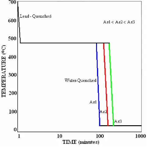
(35) Chapter 2. Memory Effect Theory and Constitutive Model Development. Constitutive Model Development: By the use of experimental data obtained from the previous stage, a constitutive model that describes the return from martensite to austenite structure according to the temperature and heat treatment is proposed.. 2.3.. TRANSFORMATION TEMPERATURE SETTING. A NiTi ribbon from Johnson Matthey Inc™ is been used for experiments. It is shown in Fig. 2-6, its nominal transformation temperatures (before heat treatment) are shown in Table 2-1. and its chemical composition is shown in Table 2-2.. Fig. 2-6. NiTi Ribbon used for experimental work Table. 2-1. Transformation Temperature for NiTi Sample (oC) As 99. Af 120. Ms 81. Mf 60. Table. 2-2. Chemical Composition of NiTi Sample (wt. %) Ni 56.10. Ti 43.50. C .043. Fe 0.041. Cr 0.005. Cu 0.003. Co 0.001. Three NiTi specimens are annealed at different times at the same temperature; resulting in a specific transformation temperature for each one. A diagram of the heat treatment process is shown in Fig. 2-6. Table 2-3 shows the temperatures and times of annealing for each specimen.. Table. 2-3. Temperatures and Times of Heat Treatment for each NiTi specimen.. Specimen 1. Microstructure Homogenization 30 minutes @ 715oC. 90 minutes @ 475oC. Specimen 2. 30 minutes @ 715oC. 150 minutes @ 475oC. Specimen 3. 30 minutes @ 715oC. 240 minutes @ 475oC. 32. Annealing. Manuel Ignacio Varela Jiménez.
(36) Chapter 2. Memory Effect Theory and Constitutive Model Development. A furnace 1 at 715oC is used for microstructure homogenization and a furnace 2 at 475oC is used for annealing. Lead is contained inside a ceramic recipient inside furnace 2. After the homogenization time, melt Lead is extracted from furnace 2 and put inside furnace 1, where NiTi specimen is put inside the melt Lead at ∼475oC in order to give specimens a quick temperature change. After the temperature change, the specimen inside the melt Lead is taken to the furnace 2 to complete the annealing process.. After the annealing time, specimen is taken out from melt Lead and water-quenched. Fig. 2-7 shows graphically the heat treatment process which is done for every specimen.. Fig. 2-7. Heat Treatment Process for setting a different As transformation temperature for three NiTi specimens.. 33. Manuel Ignacio Varela Jiménez.
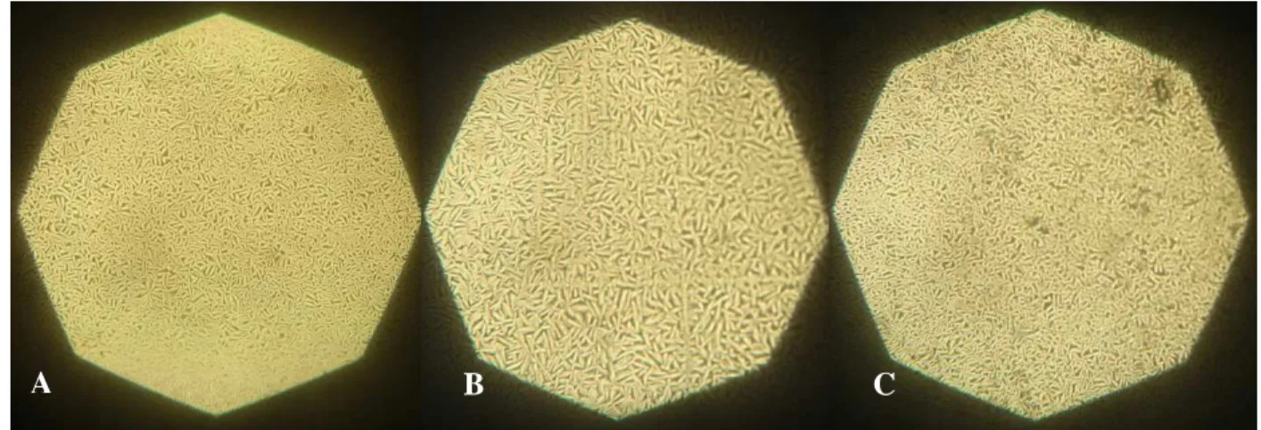
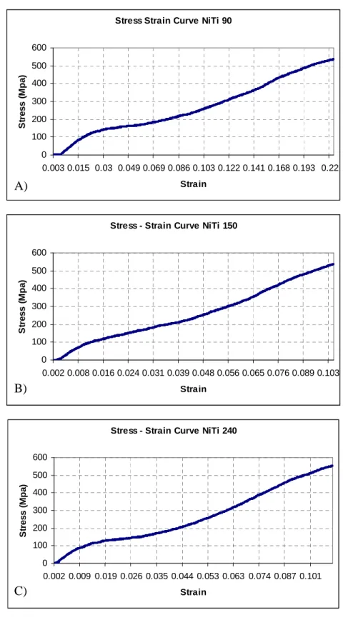
(37) Chapter 2. Memory Effect Theory and Constitutive Model Development. When heat treatment is finished, metallographic analysis is done on each specimen in order to determine if As temperature is at room temperature. Figs. 2-8 show metallographic image of each specimen, demonstrating that after the material has been cooled martensite structure has been generated, thus, As is above room temperature.. A. B. C. Fig. 2-8. Metallographic analysis of NiTi specimens, each one showing martensite structure at room temperature. A) Annealed 90 min, B) Annealed 150 min, C) Annealed 240 min. 2.4.. THERMO-MECHANICAL TEST. The length, width and thickness of NiTi specimens are measured with a Mitutoyo™ vernier. After, stress is applied to specimens by the use of a universal machine; the stress-strain curves for each material sample are shown in Fig. 2-9.. When the mechanical test is done, the width, measure and thickness of specimens are measured again with a Vernier. Considering that martensite structure has a greater volume than austenite, after the strain application the phase transformation from austenite to martensite has occurred.. For demonstrate the return from martensite to austenite heat is applied to the material. It is done by the use of engine oil heated at a specific temperature, verified by a Fluke™ thermometer. As shown in Fig. 2-10, each NiTi specimen is deposited on it during 1 minute,. 34. Manuel Ignacio Varela Jiménez.
(38) Chapter 2. Memory Effect Theory and Constitutive Model Development. after that time the length of the material is measured, showing the shape memory effect demonstrated by the original length recovery. Stress Strain Curve NiTi 90 600 Stress (Mpa). 500 400 300 200 100 0 0.003 0.015 0.03 0.049 0.069 0.086 0.103 0.122 0.141 0.168 0.193 0.22 Strain. A). Stress - Strain Curve NiTi 150 600 Stress (Mpa). 500 400 300 200 100 0 0.002 0.008 0.016 0.024 0.031 0.039 0.048 0.056 0.065 0.076 0.089 0.103. B). Strain. Stress - Strain Curve NiTi 240 600 Stress (Mpa). 500 400 300 200 100 0 0.002 0.009 0.019 0.026 0.035 0.044 0.053 0.063 0.074 0.087 0.101. C). Strain. Fig. 2-9. Stress – Strain Curve for NiTi samples during mechanical test. A) NiTi Annealed 90 min, B) NiTi Annealed 150 min, C) NiTi Annealed 240 min. 35. Manuel Ignacio Varela Jiménez.
(39) Chapter 2. Memory Effect Theory and Constitutive Model Development. Fig. 2-10. Experimental work on NiTi by heating and measuring length reduction.. As oil temperature is increased the material length is reduced, demonstrating the martensite to austenite transformation. However, it must be considered that heat also causes thermal expansion of NiTi and that the measured volume of the material during heating should consider a fraction of volume increased by this phenomenon.. After the material has been heated, it is air-cooled at room temperature and its length is measured during this time, showing an increase in length, this way, it is demonstrated that austenite is transformed in martensite because of the cooling, since Ms above room temperature.. In order to estimate the austenite volume fraction, it is considered that the material with largest elongation has 100% of martensite microstructure and that material with the minimal volume when heat is applied has 100% of austenite microstructure. It is considered that the material with volume between these extremes has a blend of austenite and martensite microstructures.. The 100% austenitic sample is heated, thus, its volume is increased because of thermal expansion.. 36. Manuel Ignacio Varela Jiménez.
(40) Chapter 2. Memory Effect Theory and Constitutive Model Development. This way, total volumes VT for material for three cases can be estimated: 100% Martensite:. VT = Vα ''. (1). 100% Austenite, in this case a fraction of the volume Vte due to thermal expansion increases:. VT = Vγ + Vte. (2). VT = Vγ V fγ + VαV fα '. (3). Martensite and Austenite:. By the use of these considerations, the volume at different temperatures is calculated. Fig. 211 shows the relation between material volume and temperature. The figure also demonstrates that as longer is the annealing time on the material the temperature to start austenite transformation is greater. Volume Reduction During Heating Volume Increase During Cooling. Volume (mm 3). 480 475. 90 min. 470. 150 min. 465. 240 min. 460. 90R. 455. 150R. 450. 240R. 445 0. 50. 100. 150. 200. 250. Tem perature (oC). Fig. 2-11. NiTi volume reduction during heating and volume increase during cooling ‘R’.. 37. Manuel Ignacio Varela Jiménez.
(41) Chapter 2. Memory Effect Theory and Constitutive Model Development. 2.5. CONSTITUTIVE RELATION DURING TEMPERATURE INCREASE AND RETURN OF ACHIEVED STRAIN. By the use of equation (3), volume fraction of austenite is estimated; these experimental values are used to develop the constitutive model, which are plotted in Fig. 2-12 defining how temperature induces austenite volume fraction increases, at the same time, detwinned martensite volume fraction decreases.. Volume Fraction on Austenite / Martensite. Experimental Austenite Volume Fraction vs Temperature 1 90 min. 0.8. 150 min. 0.6. 240 min. 0.4. 90m 150m. 0.2. 240m. 0 0. 50. 100. 150. 200. 250. o. Tem perature ( C). Fig. 2-12. Relation of Experimental Austenite Volume Fraction and Temperature. Heat treatment affects the transformation temperature.. Taking 100oC as reference, it is demonstrated how the specimen with shorter heat treatment times requires less temperature to induce a higher amount of austenite volume fraction.. Starting from equation, based in previous work [2.9] on austenitic stainless steels a constitutive model for first stage is defined by:. σ t = σ α ′′ ⋅ V fα ′′ + σ γ ⋅ V fγ. (4). Where:. σt = Strength of NiTi Alloy. σγ= Strength of austenitic structure. σα’’= Strength of austenitic structure. Vfγ= Volumetric Fraction of austenitic structure 38. Manuel Ignacio Varela Jiménez.
(42) Chapter 2. Memory Effect Theory and Constitutive Model Development. The strain induced structure can be defined by Fig 2-12, considering a characteristic temperature Tc defined by the point where the volume fraction of austenite and martensite is 0.5. From the same figures, equations (5)-(6) can be expressed as:. V fγ. T = 1 + x TC. . B. . −1. (5). Where:. V fγ + V fα ′′ = 1. (6). Tx = Temperature of NiTi alloy. From experimental data, Fig. 2-13 and Fig. 2-14 show the characteristic temperature Tc and B constant, respectively, as a function of Annealing Time. Tc vs Heat Treatment Time 137.5. Tc (o C). 137 136.5 136 135.5 y = 0.0002x 2 - 0.0721x + 142. 135 0. 50. 100. 150. 200. 250. 300. Heat Treatment Time (minutes). Fig. 2-13.Characteristic Temperature Tc vs Heat Treatment Time B vs Heat Treament Time 0 -10. 0. 50. 100. 150. 200. 250. 300. B. -20 -30. y = 0.0027x 2 - 1.0681x + 55.7. -40 -50 -60 Heat Treatment Time (minutes). Fig. 2-14. B constant vs Heat Treatment Time. 39. Manuel Ignacio Varela Jiménez.
(43) Chapter 2. Memory Effect Theory and Constitutive Model Development. With these data and by the use of minimal squares technique, equations (7) and (8) are defined: Tc = 0 . 0002 t 2 − . 0721 t + 142. (7). B = 0.0027t 2 − 1.068t + 55.7. (8). Where t is the heat treatment duration time.. Considering the heat treatment duration time, the constants for equation (5) are determined. This way the model is complete and its results are shown in Fig. 2-15.. Austenite Volume Fraction. Austenite Phase Transformation 1 0.9 0.8 0.7 0.6 0.5 0.4 0.3 0.2 0.1 0. 90 aprox 150 aprox 240 aprox. 0. 100. 200. 300. 400. o. Temperature ( C) Fig. 2-15. Austenite Volume Fraction estimated by constitutive model.. Fig. 2-15 can also demonstrate that the NiTi specimen with shorter heat treatment duration (90 minutes) has the minimal As temperature.. Austenite and Detwinned Martensite have their own mechanical properties, as shown in Fig. 2-16.. 40. Manuel Ignacio Varela Jiménez.
(44) Chapter 2. Memory Effect Theory and Constitutive Model Development. Fig. 2-16. Stress for the austenite and detwinned martensite.. Each stress can be quantified through equations (14)-(17):. σ γ = kγ ε n. (9). σ α ′′ = k ′′ε n. (10). kγ = aγ 0 + aγ 1T. (11). k ′′ = a0′′ + a1′′T. (12). Where kγ and kα’’ are material constants and n and n’’ can be set in function of the temperature, as with every constant.. Fig. 2-17 shows the kγ and kα’’ constants in function of the temperature for twinned martensite and austenite.. Fig. 2-17. Constants as a function of temperature for twinned martensite and austenite. 41. Manuel Ignacio Varela Jiménez.
(45) Chapter 2. Memory Effect Theory and Constitutive Model Development. Fig. 2-18 shows the Stress-Strain relation during strain and the strength because of the temperature.. Fig. 2-18. Stress-Strain relation due to temperature. Thus, depending of As, the return of strength-strain can be described in Fig. 2-18 and the equation (13):. T γ σ tr = kγ ε n 1 + x Tc. . B. −1 B −1 Tx n′′ ′ ′ + k ε 1 − 1 + (13) Tc . Where ε is the material strain. Equation (13) becomes the expression that predicts the mechanical properties in function of the transformation temperature during return at the original conditions of NiTi.. 42. Manuel Ignacio Varela Jiménez.
(46) Chapter 2. Memory Effect Theory and Constitutive Model Development. 2.6.. CHAPTER REMARKS. Experimental data obtained demonstrate that transformation temperature is increased according to heat treatment time; this fact is also demonstrated by the constitutive model. However, experimental data must be improved considering the thermal expansion on the material because of heating.. The experimental work and the model demonstrate that as longer is the heat treatment time, greater is the temperature necessary to complete the austenite transformation.. At constant temperature, NiTi with lower transformation temperature has the largest austenite volume fraction increase.. Constitutive model developed in this work is simple, compared to others found in literature. The variables involved, such as volume and temperature are easy to measure.. Practical applications can be given to the model, such as stents design; through the model the expansion of the device could be predicted and the transformation temperature, force and stress of the material could be validated to guarantee the correct operation of the device.. The model involves the heat duration time, this way, it can be estimated how much time the material must be heated in order to set a specific transformation temperature, in stents, this can be very useful, allowing to establish a method for setting body temperature as the transformation temperature. The method even could be patented.. Considering further work, a heat treatment for setting room temperature of the material must be determined. During this work, microstructure homogenization time was of 15 minutes and can be supposed that it was too long for the dimensions of the specimen, thus, a shorter microstructure homogenization time should be considered. Also, the relation of the constants and the model developed in this work must be related with the equations for stress of NiTi during phase transformation from martensite to austenite.. 43. Manuel Ignacio Varela Jiménez.
(47) Chapter 2. Memory Effect Theory and Constitutive Model Development. 2.9.. REFERENCES. [2.1]. Ryhänen J. “Biocompatibility Evaluation Of Nickel-Titanium Shape Memory Metal Alloy”. Academic Dissertation. University of Oulu. (1999).. [2.2]. McNaney J.M, Imbeni V, Jung Y, Papadopoulos P, Ritchie R.O. “An experimental study of the superelastic effect in a shape-memory Nitinol alloy under biaxial loading”. Mechanics of Materials. Vol 35. pp 969–986. (2003).. [2.3]. Nemat-Nasser S, Guo W. “Superelastic and cyclic response of NiTi SMA at various strain rates and temperatures”. Mechanics of Materials. Vol 38. pp 463–474. (2006).. [2.4]. Ng K.L, Sun Q.P. “Stress-induced phase transformation and detwinning in NiTi polycrystalline shape memory alloy tubes”. Mechanics of Materials. Vol 38. pp 41– 56. (2006).. [2.5]. Martínez, O. “Materials for Manufacture Class Notes”. Fall 2007. ITESM Monterrey Campus. (2007).. [2.6]. De Castro J A, Melcher K J, Noebe R D, Gaydosh D J. “Development of a numerical model for high-temperature shape memory alloys”. Smart Materials and Structures. Vol 16. pp 2080-2090. (2007).. [2.7]. Pelton A.R, DiCello J, Miyazaki S. “Optimization of processing and properties of medical grade Nitinol wire”. Minimally Invasive Therapy and Allied Technologies. Vol 9(1). pp 107–118. (2000).. [2.8]. Malukhin K, Ehmann K. “Material Characterization of NiTi Based Memory Alloys Fabricated by the Laser Direct Metal Deposition Process”. Journal of Manufacturing Science and Engineering. Vol 128.. [2.9]. Cortes J. “Analysis of Flow Stress and Martensitic Phase Transformation on Austenitic Stainless Steels Under Cold Working”. Hiroshima University. PhD Thesis. (1993).. 44. Manuel Ignacio Varela Jiménez.
(48) Chapter 3. Principles for Design and Manufacture of NiTi Stents. PART II. APPLICATION. 3.. PRINCIPLES FOR DESIGN AND MANUFACTURE OF NICKEL – TITANIUM ALLOY CARDIOVASCULAR STENTS. 3.1.. BACKGROUND. Numerous treatments exist to cure atherosclerosis [3.1]. Currently, two common procedures for patients not responding adequately to pharmacologic therapy are Coronary Artery Bypass Grafting (CABG) and Percutaneous Transluminal Coronary Balloon Angioplasty (PTCA) [3.2], also known as angioplasty, consisting of a less invasive procedure [3.3] based in catheter, pioneered by Andreas Gruentzig in the late 1970’s [3.4].. PTCA is widely used today [3.5]; it consists of opening clogged arteries [3.3] by dilating them [3.5], most commonly, by inflating a tiny balloon on a catheter into the artery [3.3]. The balloon tip catheter is pushed along a guide wire to the lesion site. The balloon is then inflated to compress the plaque against the artery wall and, hence, the plaque is squeezed along the artery wall, restoring the opening of the artery to allow increased blood flow. However, this method may cause the lining of the arterial wall to tear or sag [3.3], thus, the procedure is not always successful; restenosis, defined as ‘the arterial healing response after injury incurred during coronary revascularization’ has been the principal drawback of PTCA since its inception [3.6]. One of the first pathological descriptions of restenosis described a proliferative fibrocellular response, known as hyperplasia, which occludes the coronary lumen. [3.4].. The lack of long term efficacy of angioplasty and the physical toll associated with major coronary surgery have prompted the search for new technologies [3.2] to decrease the incidence of restenosis after angioplasty [3.4]. Therefore, since 1980’s [3.1], stents have been used to improve angioplasty and have gained popularity among cardiac surgeons [3.1]. The advent of these devices has profoundly changed PTCA and treatment strategies of numerous other problems [3.7].. 45. Manuel Ignacio Varela Jiménez.
(49) Chapter 3. Principles for Design and Manufacture of NiTi Stents. The term ‘stent’ is attributed to the dentist Charles T. Stent, who used to support poorly aligned teeth with a special apparatus, in the nineteen century. In the medical literature, the first mention of the word ‘stent’ is found in a paper about reconstruction of the biliary duct in dogs in 1954. Some of the first stents works were developed by Maass, who published data in 1984 about mechanically self expanding stents for use in peripheral arteries. Other similar works were published in 1985 by Gianturco, who developed a spring loaded self expanding stent [3.8].. According to Scott [3.4], the era of coronary stenting began in 1987 when Sigwart described the placement of self expanding stents in the coronary arteries of patients who presented restenosis or abrupt closure after CABG or PCTA. However, Gay et al [3.5] consider stenting was introduced by Dr. Julio Palmaz in 1988.. Stent development was complicated; the results of well designed randomized trials proved that stent implantation in elective cases could reduce restenosis rates and improve the patient’s clinical outcome, as compared with PCTA. Eventually, the implantation technique has been improved by focusing on full expansion, adequate deployment of the stent using intravascular ultrasound, and by the use of simplified and more effective anticoagulation protocols. Since then, the stent has gained ground at an incredible speed [3.8].. Nowadays, coronary stenting is the dominant percutaneous coronary intervention modality [3.9]. However, the deep vascular trauma imposed by stent struts produce more hyperplasia than balloon angioplasty in experimental animals and in humans [3.10]. Then, their biomechanical properties are considered to have much influence on long term clinical results after implant procedure [3.11].. The majority of stents in use today are composed of balloon expandable 316L stainless steel or NiTi [3.12] because of their mechanical properties, nevertheless other materials, such as Platinum, Iridium, Tantalum, or Cobalt alloy have been used to improve the tissue response or stents implantation. For example, in ‘Atlas’™ stent, shown in Fig. 3-1, Platinum is used because it is considered a biocompatible material with low tendency to platelet adhesion and. 46. Manuel Ignacio Varela Jiménez.
(50) Chapter 3. Principles for Design and Manufacture of NiTi Stents. thrombosis [3.13]. In ‘Smart Control’™ stent, shown in Fig. 3-2, NiTi is the main material of the structure, but Tantalum markers are added to improve the radiopacity of the device and facilitate stent implantation.. Fig. 3-1. ‘Atlas’™ stent, applying a Platinum – Iridium Alloy. It has been developed in Mexico [3.13].. Fig. 3-2. ‘Smart Control’™ stent. The main structure uses NiTi. Tantalum markers (inside the circles) have been added to improve radiopacity of the device [Johnson & Johnson™].. Due to the small dimensions of stents, in micrometers range; its manufacture becomes complicated. In general, mechanical machining systems are difficult to use when features dimensions fall below 110 micrometers, such as stents in Fig. 3-3; this difficulty is increased when materials to machine are difficult to work or advanced metal alloys [3.14], like NiTi.. Because of difficulties for cutting in small dimensions, several methods have been used for metallic stent manufacturing, becoming the laser cutting systems the most advantageous over other techniques such as etching and electroforming. For example, in the case of etching, the formation of ‘etching lip’ may lead to undesirable side effects, whereas in the laser processing method a straight edge is produced with desired taper, resulting in a uniform fluid flow into the blood vessel [3.15]. Also, the processes are slow and expensive compared to the laser techniques.. 47. Manuel Ignacio Varela Jiménez.
Figure
![Fig. 1-1. Phase Diagram for NiTi [1.4]](https://thumb-us.123doks.com/thumbv2/123dok_es/3210681.581815/14.918.148.794.203.688/fig-phase-diagram-for-niti.webp)

![Fig. 1-4. Martensite Volume Fraction vs Strain at different temperatures and its constitutive model [1.5]](https://thumb-us.123doks.com/thumbv2/123dok_es/3210681.581815/16.918.255.729.192.564/martensite-volume-fraction-strain-different-temperatures-constitutive-model.webp)

+7


Documento similar
"Preliminary Investigation of the effects of surface treatments on biological response to shape memory NiTi stents", Journal of Biomedical Materials Research
On the other hand at Alalakh Level VII and at Mari, which are the sites in the Semitic world with the closest affinities to Minoan Crete, the language used was Old Babylonian,
Díaz Soto has raised the point about banning religious garb in the ―public space.‖ He states, ―for example, in most Spanish public Universities, there is a Catholic chapel
Parameters of linear regression of turbulent energy fluxes (i.e. the sum of latent and sensible heat flux against available energy).. Scatter diagrams and regression lines
It is generally believed the recitation of the seven or the ten reciters of the first, second and third century of Islam are valid and the Muslims are allowed to adopt either of
ABSTRACT Transformation of the Specialized Knowledge of Future Primary Teachers on Fraction Division
From the phenomenology associated with contexts (C.1), for the statement of task T 1.1 , the future teachers use their knowledge of situations of the personal
In the preparation of this report, the Venice Commission has relied on the comments of its rapporteurs; its recently adopted Report on Respect for Democracy, Human Rights and the Rule
The draft amendments do not operate any more a distinction between different states of emergency; they repeal articles 120, 121and 122 and make it possible for the President to
