EC 1251 Guía Mesh Current pdf
44
0
0
Texto completo
(2) Figure 1: The circuit for Mesh Current Example 1 6. Solve the equations and check your solution using a power balance. If the power balances, use the solution to calculate the desired output value for the circuit. First we present an example that contains only resistors and independent voltage sources. Once you have mastered these types of circuits we move on to circuits containing dependent voltage sources, and then to circuits containing current sources.. Mesh Current Example 1 Using the mesh current method, ¯nd io for the circuit in Fig. 1. Solution 1. Identify all of the meshes in the circuit by drawing curved arrows in the center of the mesh in the direction of the current °ow. The direction of the current °ow is arbitrary, but to be consistent we will always de¯ne the direction of current °ow as clockwise. The current arrows are shown in Fig. 2. 2. Assign a variable name for each mesh current and label the current arrow in each mesh. The chosen variable names are also shown in Fig. 2. Remember that the mesh currents are the currents that exist on the perimeter of each mesh. When a component belongs to only one mesh, its current is the same as the mesh current. When a component belongs to two meshes, its current is the sum of the mesh currents, where the sum must take the mesh current directions into account. 3. Write a KVL equation around each of the meshes in the direction of the current arrow. It is a good idea to put a little \x" at the point on the mesh where you start. In the left mesh, we will start just below. 2.
(3) Figure 2: The circuit for Mesh Current Example 1, with the mesh currents de¯ned the 30V source, and in the right mesh, we will start to the left of the 18V source. left mesh: ¡30 + 10i1 + 3(i1 ¡ i2 ) + 8i2 = 0 right mesh: ¡18 + 2i2 + 1i2 + 3(i2 ¡ i1 ) = 0 Note that there are two unknowns, the two mesh currents i1 and i2 , and two equations in terms of those unknowns. 4. Write any supplemental equations. In this example there are no supplemental equations, since there are no dependent sources or current sources in the circuit. Also, we have already written a su±cient number of equations to solve for all of the unknowns. 5. Place the equations in standard form. The form we use collects all of the terms involving each of the unknowns on the left-hand side of each equation, and collects the constants on the right-hand side of the equation. The standard form for the mesh current equations is shown below: i2 (¡3) = 30 left mesh: i1 (10 + 3 + 8) + right mesh: i1 (¡3) + i2 (2 + 1 + 3) = 0 Note that there are two terms on the left-hand side of each equation, one for each of the two unknown mesh currents, and each mesh current variable appears in the same position in each equation. Be sure to check your standard form equations against your original mesh current equations to make sure you have not made an errors. 6. Solve the equations and check your solution. When these equations are input into a calculator, the solution is i1 = 2 A;. i2 = 4 A. 3.
(4) Figure 3: The circuit for Mesh Current Example 1, solved The circuit is repeated in Fig. 3 with the values of all the currents through every component labeled. Using the values in Fig. 3 we can calculate the power for each component: p30V p18V p10− p3− p8− p2− p1−. = = = = = = =. ¡vi ¡vi i2 R i2 R i2 R i2 R i2 R. = ¡(30)(2) = ¡60 W; = ¡(18)(4) = ¡72 W; = 22 (10) = 40 W; = 22 (3) = 12 W; 2 = 2 (8) = 32 W; 2 = 4 (2) = 32 W; = 42 (1) = 16 W;. Thus, X. p = ¡60 ¡ 72 + 40 + 12 + 32 + 32 + 16 = 0 W. checks. The power balance veri¯es that we have the correct solution, so io = i1 = 2 A. Now try using the mesh current method for each of the practice problems below.. 4.
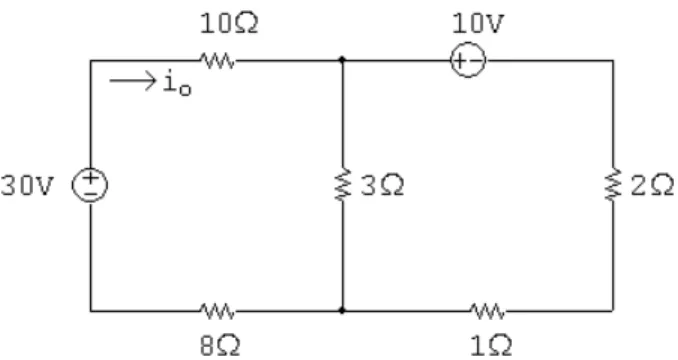
(5) Figure 4: The circuit for Mesh Current Practice Problem 1.. Mesh Current Practice Problem 1 Find io for the circuit in Fig. 4. 1. Identify all of the meshes in the circuit by drawing a curved arrow in the center of each mesh in Fig. 4 to represent the direction of the current in that mesh. 2. Assign variable names to all of the mesh currents by labeling the mesh current arrows in Fig. 4. 3. Write a KVL equation around each of the meshes in the direction of the current arrow.. 4. Are any supplemental equations required? If not, why not? If so, write them in the space below.. 5.
(6) 5. Express all of the equations in standard form.. 6. Solve the equations, using a calculator, a computer tool, or Cramer's method.. Check your solution by calculating the power for each element and summing the power for all elements.. Calculate io .. 6.
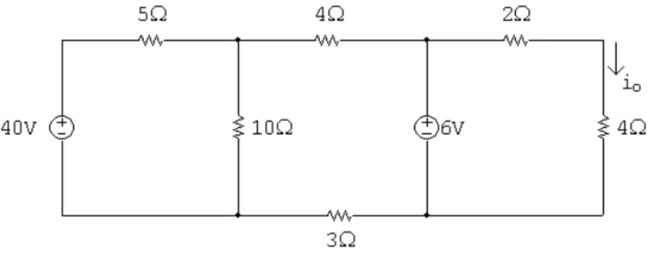
(7) Figure 5: The circuit for Mesh Current Practice Problem 2.. Mesh Current Practice Problem 2 Find io for the circuit in Fig. 5. 1. Identify all of the meshes in the circuit by drawing a curved arrow in the center of each mesh in Fig. 5 to represent the direction of the current in that mesh. 2. Assign variable names to all of the mesh currents by labeling the mesh current arrows in Fig. 5. 3. Write a KVL equation around each of the meshes in the direction of the current arrow.. 4. Are any supplemental equations required? If not, why not? If so, write them in the space below.. 7.
(8) 5. Express all of the equations in standard form.. 6. Solve the equations, using a calculator, a computer tool, or Cramer's method.. Check your solution by calculating the power for each element and summing the power for all elements.. Calculate io .. 8.
(9) Figure 6: The circuit for Mesh Current Practice Problem 3.. Mesh Current Practice Problem 3 Find vo for the circuit in Fig. 6. 1. Identify all of the meshes in the circuit by drawing a curved arrow in the center of each mesh in Fig. 6 to represent the direction of the current in that mesh. 2. Assign variable names to all of the mesh currents by labeling the mesh current arrows in Fig. 6. 3. Write a KVL equation around each of the meshes in the direction of the current arrow.. 4. Are any supplemental equations required? If not, why not? If so, write them in the space below.. 9.
(10) 5. Express all of the equations in standard form.. 6. Solve the equations, using a calculator, a computer tool, or Cramer's method.. Check your solution by calculating the power for each element and summing the power for all elements.. Calculate vo .. 10.
(11) Figure 7: The circuit for Mesh Current Practice Problem 4.. Mesh Current Practice Problem 4 Find the power dissipated in the 32− resistor for the circuit in Fig. 7. 1. Identify all of the meshes in the circuit by drawing a curved arrow in the center of each mesh in Fig. 7 to represent the direction of the current in that mesh. 2. Assign variable names to all of the mesh currents by labeling the mesh current arrows in Fig. 7. 3. Write a KVL equation around each of the meshes in the direction of the current arrow.. 4. Are any supplemental equations required? If not, why not? If so, write them in the space below.. 11.
(12) 5. Express all of the equations in standard form.. 6. Solve the equations, using a calculator, a computer tool, or Cramer's method.. Check your solution by calculating the power for each element and summing the power for all elements.. Calculate p32− .. 12.
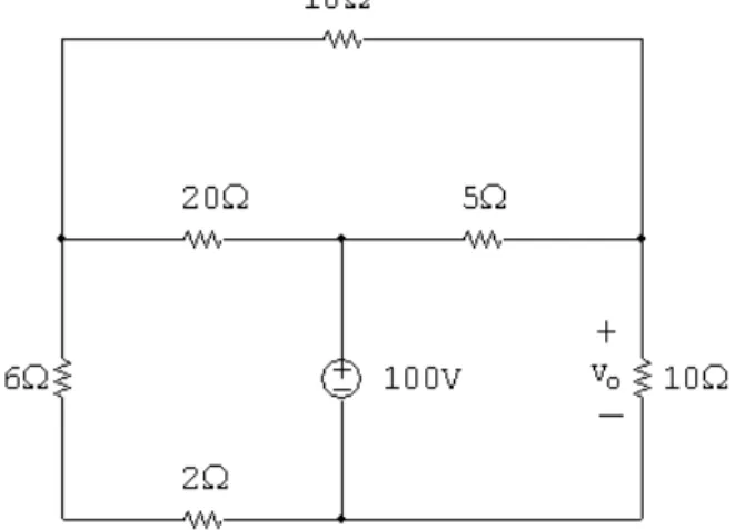
(13) Figure 8: The circuit for Mesh Current Practice Problem 5.. Mesh Current Practice Problem 5 Find vo for the circuit in Fig. 8. 1. Identify all of the meshes in the circuit by drawing a curved arrow in the center of each mesh in Fig. 8 to represent the direction of the current in that mesh. 2. Assign variable names to all of the mesh currents by labeling the mesh current arrows in Fig. 8. 3. Write a KVL equation around each of the meshes in the direction of the current arrow.. 4. Are any supplemental equations required? If not, why not? If so, write them in the space below.. 13.
(14) 5. Express all of the equations in standard form.. 6. Solve the equations, using a calculator, a computer tool, or Cramer's method.. Check your solution by calculating the power for each element and summing the power for all elements.. Calculate vo .. 14.
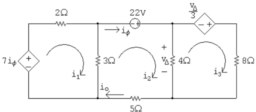
(15) Figure 9: The circuit for Mesh Current Example 2. Figure 10: The circuit for Mesh Current Example 2, with the mesh currents de¯ned. Mesh Current Example 2 Using the mesh current method, ¯nd io for the circuit in Fig. 1. Solution 1. Identify all of the meshes in the circuit by drawing curved arrows in the center of the mesh in the direction of the current °ow. As usual, we de¯ne the direction of current °ow as clockwise. The current arrows are shown in Fig. 10. 2. Assign a variable name for each mesh current and label the current arrow in each mesh. The chosen variable names are also shown in Fig. 10. 3. Write a KVL equation around each of the meshes in the direction of the current arrow. In the left mesh, we will start just below the dependent source, in the center mesh we start just to the left of the 22V source,. 15.
(16) and in the right mesh we will start to the left of the dependent source. = 0 left mesh: ¡7iÁ + 2i1 + 3(i1 ¡ i2 ) center mesh: ¡22 + 4(i2 ¡ i3 ) + 5i2 + 3(i2 ¡ i1 ) = 0 v¢ right mesh: ¡ + 8i3 + 4(i3 ¡ i2 ) = 0 3 Note that there are ¯ve unknowns, the three mesh currents i1 , i2 , and i3 , the current iÁ that controls one dependent source and the voltage v¢ that controls the other dependent source. Yet there are only three KVL equations. This means we have to specify two more equations. 4. Write any supplemental equations. This is where the remaining two equations will be developed. Whenever there are dependent sources in the circuit, we will need to write a supplemental equation for each dependent source that de¯nes the current or voltage used to control each source in terms of the mesh currents in our circuit. These supplemental equations are also called constraint equations because they constrain the relationship between two or more unknowns in our circuit. Thus, one of the unknowns is no longer an independent variable byt rather is dependent on the other independent variables in the circuit. Now turn to the circuit in Fig. 10. Notice that the controlling current iÁ is the same as the mesh current i2 . Thus, our ¯rst constraint equation is iÁ = i2 From the circuit we see that the controlling voltage v¢ is the voltage drop across the 4− resistor. We use Ohm's Law to de¯ne that voltage drop in terms of the current °owing through the resistor. The current °owing through the resistor in the direction of the voltage drop must be de¯ned in terms of the mesh currents, so is equal to i2 ¡ i3 . Thus, our second constraint equation is v¢ = 4(i2 ¡ i3 ) The three KVL equations and the two constraint equations now provide the ¯ve equations needed to solve for the ¯ve unknowns in the circuit. 5. Place the equations in standard form. This is shown below: left mesh: i1 (2 + 3) center mesh: i1 (¡3) right mesh: i1 (0) constraint: i1 (0) constraint: i1 (0). + i2 (¡3) + i2 (3 + 4 + 5) + i2 (¡4) + i2 (1) + i2 (¡4). + i3 (0) + i3 (¡4) + i3 (4 + 8) + i3 (0) + i3 (4). 16. + iÁ (¡7) + iÁ (0) + iÁ (0) + iÁ (¡1) + iÁ (0). + v¢ (0) + v¢ (0) + v¢ (¡1=3) + v¢ (0) + v¢ (1). = 0 = 22 = 0 = 0 = 0.
(17) Figure 11: The circuit for Mesh Current Example 2, solved 6. Solve the equations and check your solution. When these equations are input into a calculator, the solution is i1 = 10 A;. i2 = 5 A;. i3 = 2 A;. iÁ = 5 A;. v¢ = 12 V. The circuit is repeated in Fig. 11 with the values of all the currents through every component labeled. Using the values in Fig. 11 we can calculate the power for each component: p7iÁ p22V pv¢ =3 p2− p3− p5− p4− p8−. = = = = = = = =. ¡vi ¡vi ¡vi i2 R i2 R i2 R i2 R i2 R. = ¡[7(5)](10) = ¡350 W; = ¡(22)(5) = ¡110 W; = ¡[12=3](2) = ¡8 W; 2 = 10 (2) = 200 W; 2 = 5 (3) = 75 W; = 52 (5) = 125 W; = 32 (4) = 36 W; 2 = 2 (8) = 32 W;. Thus, X. p = ¡350 ¡ 110 ¡ 8 + 200 + 75 + 125 + 36 + 32 = 0 W. checks. The power balance veri¯es that we have the correct solution, so io = i2 = 5 A. Now try using the mesh current method for each of the practice problems below.. 17.
(18) Figure 12: The circuit for Mesh Current Practice Problem 6.. Mesh Current Practice Problem 6 Find io for the circuit in Fig. 12. 1. Identify all of the meshes in the circuit by drawing a curved arrow in the center of each mesh in Fig. 12 to represent the direction of the current in that mesh. 2. Assign variable names to all of the mesh currents by labeling the mesh current arrows in Fig. 12. 3. Write a KVL equation around each of the meshes in the direction of the current arrow.. 4. Are any supplemental equations required? If not, why not? If so, write them in the space below.. 18.
(19) 5. Express all of the equations in standard form.. 6. Solve the equations, using a calculator, a computer tool, or Cramer's method.. Check your solution by calculating the power for each element and summing the power for all elements.. Calculate io .. 19.
(20) Figure 13: The circuit for Mesh Current Practice Problem 7.. Mesh Current Practice Problem 7 Find vo for the circuit in Fig. 13. 1. Identify all of the meshes in the circuit by drawing a curved arrow in the center of each mesh in Fig. 13 to represent the direction of the current in that mesh. 2. Assign variable names to all of the mesh currents by labeling the mesh current arrows in Fig. 13. 3. Write a KVL equation around each of the meshes in the direction of the current arrow.. 4. Are any supplemental equations required? If not, why not? If so, write them in the space below.. 20.
(21) 5. Express all of the equations in standard form.. 6. Solve the equations, using a calculator, a computer tool, or Cramer's method.. Check your solution by calculating the power for each element and summing the power for all elements.. Calculate vo .. 21.
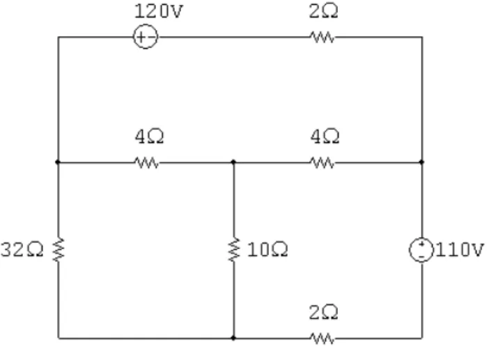
(22) Figure 14: The circuit for Mesh Current Practice Problem 8.. Mesh Current Practice Problem 8 Find the power delivered in the circuit in Fig. 14. 1. Identify all of the meshes in the circuit by drawing a curved arrow in the center of each mesh in Fig. 14 to represent the direction of the current in that mesh. 2. Assign variable names to all of the mesh currents by labeling the mesh current arrows in Fig. 14. 3. Write a KVL equation around each of the meshes in the direction of the current arrow.. 4. Are any supplemental equations required? If not, why not? If so, write them in the space below.. 22.
(23) 5. Express all of the equations in standard form.. 6. Solve the equations, using a calculator, a computer tool, or Cramer's method.. Check your solution by calculating the power for each element and summing the power for all elements.. Calculate pdelivered .. 23.
(24) Figure 15: The circuit for Mesh Current Practice Problem 9.. Mesh Current Practice Problem 9 Find the power for the 15− resistor in the circuit in Fig. 15. 1. Identify all of the meshes in the circuit by drawing a curved arrow in the center of each mesh in Fig. 15 to represent the direction of the current in that mesh. 2. Assign variable names to all of the mesh currents by labeling the mesh current arrows in Fig. 15. 3. Write a KVL equation around each of the meshes in the direction of the current arrow.. 4. Are any supplemental equations required? If not, why not? If so, write them in the space below.. 24.
(25) 5. Express all of the equations in standard form.. 6. Solve the equations, using a calculator, a computer tool, or Cramer's method.. Check your solution by calculating the power for each element and summing the power for all elements.. Calculate p15− .. 25.
(26) Figure 16: The circuit for Mesh Current Practice Problem 10.. Mesh Current Practice Problem 10 Find vo in the circuit in Fig. 16. 1. Identify all of the meshes in the circuit by drawing a curved arrow in the center of each mesh in Fig. 16 to represent the direction of the current in that mesh. 2. Assign variable names to all of the mesh currents by labeling the mesh current arrows in Fig. 16. 3. Write a KVL equation around each of the meshes in the direction of the current arrow.. 4. Are any supplemental equations required? If not, why not? If so, write them in the space below.. 26.
(27) 5. Express all of the equations in standard form.. 6. Solve the equations, using a calculator, a computer tool, or Cramer's method.. Check your solution by calculating the power for each element and summing the power for all elements.. Calculate vo .. 27.
(28) Figure 17: The circuit for Mesh Current Example 3. Figure 18: The circuit for Mesh Current Example 3, with the mesh currents de¯ned.. Mesh Current Example 3 Using the mesh current method, ¯nd io for the circuit in Fig. 17. Solution 1. Identify all of the meshes in the circuit by drawing curved arrows in the center of the mesh in the direction of the current °ow. As usual, we de¯ne the direction of current °ow as clockwise. The current arrows are shown in Fig. 18. 2. Assign a variable name for each mesh current and label the current arrow in each mesh. The chosen variable names are also shown in 28.
(29) Figure 19: The circuit for Mesh Current Example 3, with a known mesh current and a supermesh. Fig. 18. 3. Write a KVL equation around each of the meshes in the direction of the current arrow. We modify this step whenever the circuit contains current sources. The circuit in Fig. 18 has two current sources. Consider ¯rst the 6A current source. This current source is on the perimeter of a mesh, meaning that the current source establishes the value of the mesh current in this mesh. Thus, i1 = 6A, so there is no need to write a KVL equation for this mesh. Now consider the 8A current source. This source is shared between two meshes, rather than being on the perimeter of a single mesh. Any time a current source is shared between two meshes, the two meshes should be combined to form a supermesh. Whenever a supermesh is present in a circuit we will write one single KVL equation for the supermesh and one constraint equation de¯ning the relationship between the two mesh currents that form the supermesh. Figure 19 shows the known value of the current in the top left mesh and identi¯es the path of the supermesh with a dashed line. Thus, in this step we write a KVL equation for each single mesh where the current is not known and for each supermesh. For the circuit in Fig. 19 we need only write the single KVL equation for the supermesh, because the remaining mesh current is known. We start just to the left of the dependent voltage source: supermesh: 29i¯ + 8i2 + 6i3 + 5(i3 ¡ 6A) + 4(i2 ¡ 6A) = 0 4. Write any supplemental equations. Since there is a dependent source in the circuit, we know we will need at least one supplemental equation. This equation de¯nes the quantity used to control the dependent source, i¯ , in terms of the labeled mesh currents. Thus, the equation is i¯ = 6A ¡ i3 29.
(30) Figure 20: The circuit for Mesh Current Example 3, solved But there is a second supplemental, or constraint, equation due to the presence of the supermesh. Remember that the current source shared between the two meshes constrains the di®erence between these mesh currents. The second constraint equation is thus i3 ¡ i2 = 8 A The single KVL equation and the two supplemental equations provide the three equations needed to solve for the three unknowns | i2 , i3 , and i¯ . Remember that i1 = 6A because of the current source on the perimeter of the top left mesh. 5. Solve the equations and check your solution. When these equations are input into a calculator, the solution is i2 = ¡4 A;. i3 = 4 A;. i¯ = 2 A. The circuit is repeated in Fig. 20 with the values of all the currents through every component labeled. In addition, we have labeled the voltage drop across each current source. The voltage drops were calculated by writing a KVL equation for a mesh containing the current source and treating the voltage drop across the current source as an unknown. For example, to calculate the voltage drop across the 6A current source, de¯ne the voltage drop as v6A (positive at the top) and write a KVL equation for the top left mesh, starting just below the 6A source and going clockwise: ¡v6A + (3−)(6A) + (4−)(10A) + (5−)(2A) = 0 Solving, we see that v6A = 68V, as indicated in Fig. 20. Using the. 30.
(31) values in Fig. 20 we can calculate the power for each component: p6A p8A p29i¯ p3− p4− p5− p6− p8−. = = = = = = = =. ¡vi ¡vi vi i2 R i2 R i2 R i2 R i2 R. = ¡(68)(6) = ¡408 W; = ¡(14)(8) = ¡112 W; = [29(2)](¡4) = ¡232 W; = 62 (3) = 108 W; 2 = 10 (4) = 400 W; = 22 (5) = 20 W; 2 = 4 (6) = 96 W; = 42 (8) = 128 W;. Thus, X. p = ¡408 ¡ 112 ¡ 232 + 108 + 400 + 20 + 96 + 128 = 0 W. checks. The power balance veri¯es that we have the correct solution, so io = i2 = ¡4 A. Now try using the mesh current method for each of the practice problems below.. 31.
(32) Figure 21: The circuit for Mesh Current Practice Problem 11.. Mesh Current Practice Problem 11 Find the power delivered to the 18− resistor in the circuit in Fig. 21. 1. Identify all of the meshes in the circuit by drawing a curved arrow in the center of each mesh in Fig. 21 to represent the direction of the current in that mesh. 2. Assign variable names to all of the mesh currents by labeling the mesh current arrows in Fig. 21. 3. Write a KVL equation around each of the meshes in the direction of the current arrow.. 4. Are any supplemental equations required? If not, why not? If so, write them in the space below.. 32.
(33) 5. Express all of the equations in standard form.. 6. Solve the equations, using a calculator, a computer tool, or Cramer's method.. Check your solution by calculating the power for each element and summing the power for all elements.. Calculate p18− .. 33.
(34) Figure 22: The circuit for Mesh Current Practice Problem 12.. Mesh Current Practice Problem 12 Find io for the circuit in Fig. 22. 1. Identify all of the meshes in the circuit by drawing a curved arrow in the center of each mesh in Fig. 22 to represent the direction of the current in that mesh. 2. Assign variable names to all of the mesh currents by labeling the mesh current arrows in Fig. 22. 3. Write a KVL equation around each of the meshes in the direction of the current arrow.. 4. Are any supplemental equations required? If not, why not? If so, write them in the space below.. 34.
(35) 5. Express all of the equations in standard form.. 6. Solve the equations, using a calculator, a computer tool, or Cramer's method.. Check your solution by calculating the power for each element and summing the power for all elements.. Calculate io .. 35.
(36) Figure 23: The circuit for Mesh Current Practice Problem 13.. Mesh Current Practice Problem 13 Find vo for the circuit in Fig. 23. 1. Identify all of the meshes in the circuit by drawing a curved arrow in the center of each mesh in Fig. 23 to represent the direction of the current in that mesh. 2. Assign variable names to all of the mesh currents by labeling the mesh current arrows in Fig. 23. 3. Write a KVL equation around each of the meshes in the direction of the current arrow.. 4. Are any supplemental equations required? If not, why not? If so, write them in the space below.. 36.
(37) 5. Express all of the equations in standard form.. 6. Solve the equations, using a calculator, a computer tool, or Cramer's method.. Check your solution by calculating the power for each element and summing the power for all elements.. Calculate vo .. 37.
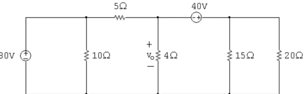
(38) Figure 24: The circuit for Mesh Current Practice Problem 14.. Mesh Current Practice Problem 14 Find the power for the 80V source in the circuit in Fig. 24. 1. Identify all of the meshes in the circuit by drawing a curved arrow in the center of each mesh in Fig. 24 to represent the direction of the current in that mesh. 2. Assign variable names to all of the mesh currents by labeling the mesh current arrows in Fig. 24. 3. Write a KVL equation around each of the meshes in the direction of the current arrow.. 4. Are any supplemental equations required? If not, why not? If so, write them in the space below.. 38.
(39) 5. Express all of the equations in standard form.. 6. Solve the equations, using a calculator, a computer tool, or Cramer's method.. Check your solution by calculating the power for each element and summing the power for all elements.. Calculate p80V .. 39.
(40) Figure 25: The circuit for Mesh Current Practice Problem 15.. Mesh Current Practice Problem 15 Find io for the circuit in Fig. 25. 1. Identify all of the meshes in the circuit by drawing a curved arrow in the center of each mesh in Fig. 25 to represent the direction of the current in that mesh. 2. Assign variable names to all of the mesh currents by labeling the mesh current arrows in Fig. 25. 3. Write a KVL equation around each of the meshes in the direction of the current arrow.. 4. Are any supplemental equations required? If not, why not? If so, write them in the space below.. 40.
(41) 5. Express all of the equations in standard form.. 6. Solve the equations, using a calculator, a computer tool, or Cramer's method.. Check your solution by calculating the power for each element and summing the power for all elements.. Calculate io .. 41.
(42) Reading ² in Introductory Circuits for Electrical and Computer Engineering: { Section 3.1 | terminology and de¯nitions { Section 3.5 | introduction to mesh current method { Section 3.6 | mesh current method with circuits containing dependent sources { Section 3.7 | supermeshes ² in Electric Circuits, sixth edition: { Section 4.1 | terminology and de¯nitions { Section 4.5 | introduction to mesh current method { Section 4.6 | mesh current method with circuits containing dependent sources { Section 4.7 | supermeshes ² Workbook section | Power Balancing in DC Circuits. Additional Problems ² in Introductory Circuits for Electrical and Computer Engineering: { 3.26 { 3.29 | 3.41 ² in Electric Circuits, sixth edition: { 4.27 { 4.30 | 4.42. Solutions ² Mesh Current Practice Problem 1 | the clockwise mesh currents are 4A, 2A, and 1A and io = 1A. ² Mesh Current Practice Problem 2 | the clockwise mesh currents are 16A, 6A, and 11A and io = 5A. ² Mesh Current Practice Problem 3 | the clockwise mesh currents are ¡5A, ¡2A, and 6A and vo = 60V. ² Mesh Current Practice Problem 4 | the clockwise mesh currents are ¡5A, ¡20A, and ¡15A and p32− = 800W. 42.
(43) ² Mesh Current Practice Problem 5 | the clockwise mesh currents are 20A, 12A, 7A, and 3A and vo = 100V. ² Mesh Current Practice Problem 6 | the clockwise mesh currents are ¡4A, 4A, and 2A and io = 2A. ² Mesh Current Practice Problem 7 | the clockwise mesh currents are 4A, 8A, ¡2A, and 3A and vo = 80V. ² Mesh Current Practice Problem 8 | the clockwise mesh currents are 4A, 6A, and 2A and pdelivered = 560W. ² Mesh Current Practice Problem 9 | the clockwise mesh currents are ¡6A, ¡2A, and ¡5A and p15− = 60W. ² Mesh Current Practice Problem 10 | the clockwise mesh currents are ¡15A, ¡10A and ¡20A and vo = 130V. ² Mesh Current Practice Problem 11 | the clockwise mesh currents are ¡5A, 15A, and 5A and p18− = 450W. ² Mesh Current Practice Problem 12 | the clockwise mesh currents are ¡15A, ¡45A, and ¡70A and io = 25A. ² Mesh Current Practice Problem 13 | the clockwise mesh currents are ¡20A, ¡40A, and ¡15A and vo = 100V. ² Mesh Current Practice Problem 14 | the clockwise mesh currents are 7A, ¡8A, and 10A and p80V = 560W (delivered). ² Mesh Current Practice Problem 15 | the clockwise mesh currents are 15A, 6A, and ¡2A and io = 9A.. 43.
(44)
(45)
Figure


+7


Documento similar
Keywords: Metal mining conflicts, political ecology, politics of scale, environmental justice movement, social multi-criteria evaluation, consultations, Latin
Díaz Soto has raised the point about banning religious garb in the ―public space.‖ He states, ―for example, in most Spanish public Universities, there is a Catholic chapel
In the same direction, if the capacitance retention (expressed as the percentage of the capacitance obtained at low current densities) is plotted versus the current density for
Even though the 1920s offered new employment opportunities in industries previously closed to women, often the women who took these jobs found themselves exploited.. No matter
In the preparation of this report, the Venice Commission has relied on the comments of its rapporteurs; its recently adopted Report on Respect for Democracy, Human Rights and the Rule
Government policy varies between nations and this guidance sets out the need for balanced decision-making about ways of working, and the ongoing safety considerations
Although some public journalism schools aim for greater social diversity in their student selection, as in the case of the Institute of Journalism of Bordeaux, it should be
In the “big picture” perspective of the recent years that we have described in Brazil, Spain, Portugal and Puerto Rico there are some similarities and important differences,
