Architecture based on open source hardware and software for designing a real time vehicle tracking device
13
0
0
Texto completo
(2) Castillo, D., Martínez, S., & Gómez, A. (2018).. I. Introduction. I. Introducción. A vehicle tracking system combines the use of automatic location services in individual vehicles with software that collects, processes, and visualizes data of the fleet. Currently, in an international scale, for every company or person having transportation vehicles, having satellite tracking system offer considerable advantages such as the management and real-time control of the vehicle fleet. This option entails some costs reduction using several functionalities and applications; furthermore, it provides an efficient route planning, optimizing the fuel usage. A cost reduction is also achieved due to the avoidance of larger inactivity time periods and unnecessary travelled kilometers, increasing the productivity and profitability.. Un sistema de rastreo de vehículos combina el uso de localización automática en vehículos individuales, con software que recopila los datos de la flota, los procesa y los visualiza. En la actualidad, a escala internacional, para cualquier compañía o persona que posea vehículos de transporte, contar con un sistema de rastreo satelital instalado en ellos ofrece grandes beneficios, que se resumen en la gestión y control en tiempo real de la flota. Esto hace posible reducir gastos a través de diversas funcionalidades y aplicaciones, una planificación eficiente de la ruta, la optimización del consumo de combustible, la reducción de los costes por tiempos de inactividad excesivos y kilómetros innecesarios, el incremento de la productividad y rentabilidad, la supervisión de la velocidad, la posibilidad de detectar robo, la reducción de los costes de mantenimiento, la posibilidad de auditar la conducta del conductor, mediante un histórico de ruta, velocidad, trayectoria y tiempos, y de la creación de geocercas, que alertan cuando el vehículo sale de la zona delimitada por el cliente. En Cuba existe una entidad nacional, la Dirección de Gestión y Control de Flota [DSGCF] del Ministerio de Transporte [MITRANS], la cual controla y supervisa a distancia la implantación y empleo del Sistema de Gestión y el Control de Flota [SGCF] en las bases, empresas, órganos de dirección y organismos, con el objetivo de elevar la eficiencia en la explotación de los medios de transporte, las embarcaciones de pesca y otros equipos. De igual forma, vela por el ahorro de combustible y previene la ocurrencia de actos de indisciplina y hechos delictivos. El sistema se encuentra instalado en más de 450 bases de transporte y en más de 30.000 vehículos en todas las provincias (González Suárez et al., 2016). En esta investigación se plantea, como problema científico: en la mayoría de las empresas cubanas que utilizan el rastreo de vehículos, el procesamiento de la información se realiza de forma diferida, luego que el vehículo termina su recorrido y se descargan los datos a una estación de monitoreo una vez que regresa a su base de transporte, por lo que no se realiza un rastreo en tiempo real. Por lo tanto, en aras de reducir los costes de logística y lograr el mejor manejo de los medios y recursos de una compañía que posea medios de transporte, se hace necesario el uso de un sistema de rastreo en tiempo real. Se plantea como objetivo general: “proponer una arquitectura de hardware y software libre que permita el control de flota de vehículos en tiempo real. A partir del objetivo general, se plantean como objetivos específicos: analizar las diferentes tecnologías empleadas en un sistema de rastreo de vehículos en tiempo real; proponer una arquitectura de hardware libre que satisfaga los requerimientos del sistema de rastreo de vehículos en tiempo real; proponer una arquitectura de software libre para el sistema de rastreo de vehículos en tiempo real; y evaluar la efectividad del dispositivo diseñado a partir de pruebas experimentales. En la sección II se exponen los resultados de una revisión bibliográfica sobre el tema; en la sección III se presenta la arquitectura de hardware y software propuesta para el diseño del dispositivo; y en la sección IV se muestran y discuten los. Other advantages of these real-time monitoring systems are: the ability to supervise the speed; the ability to avoid thefts; a reduction in the maintenance costs; the ability to assess the driver’s behavior via his/her route history, speed, trajectory, and times; and the creation of geofences which alert when the vehicle does not comply with the trajectory limited by the client. In Cuba, the national entity in charge of the control, supervision, and implementation of the Fleet Control and Management System [SGCF, Sistema de Gestión y el Control de Flota] is the Fleet Control and Management Department [DSGCF, Dirección de Gestión y Control de Flota]. The SGCF controls and supervises the implementation in companies, governmental entities, and control authorities in order to increase the efficiency in the transportation methods (either by land or water). Likewise, the SGCF looks after the fuel saving and it prevents the unwanted acts and criminal actions. The system is currently installed in more than 450 transportation buses and in more than 30,000 vehicles in all the provinces (González Suárez et al., 2016). In this research, we propose the following scientific problem: in most of the Cuban companies using vehicle tracking systems, the information processing is performed in a differed manner, i.e., after the vehicle ends its route and the data has been downloaded to a monitoring station with the vehicle in the headquarters. Consequently, a real-time tracking is not performed. For this reason, seeking to reduce costs in logistics and to improve the resources use in a company with means of transportation, the use of real-time tracking systems is required. We plan as the general objective to propose a hardware/software open source architecture to allow the control. 50. http://www.icesi.edu.co/revistas/index.php/sistemas_telematica.
(3) Architecture based in open source hardware and software for designing a real time vehicle tracking device. Sistemas & Telemática, 16(44), 49-61.. resultados de los experimentos realizados para demostrar la efectividad del dispositivo.. II. Antecedentes Varios trabajos se han desarrollado en la esfera de la investigación científica alrededor del mundo para dar solución al problema del rastreo de vehículos, de ellos se destacan los que se mencionan a continuación. Verma y Bhatia (2013) desarrollaron un sistema de rastreo que utiliza un módulo receptor del Sistema de Posicionamiento Global [GPS, Global Positioning System] para obtener la localización del vehículo; un módulo SIM300, que provee el servicio Sistema Global para las Comunicaciones Móviles [GSM, Global System for Mobile Communications] para la comunicación remota; un microcontrolador CMOS ATmega16 de 8 bits, para comunicar todos los componentes; una pastilla MAX232, para convertir los niveles de voltaje TTL-RS232; y una pantalla LCD 16x2. El software, en lenguaje C: provee la interfaz entre los módulos, recibe la localización vía GPS y la transmite vía servicio de paquetes generales [GPRS, General Packet Radio Service]; y del lado del cliente se desarrolla una aplicación Web que utiliza Google Maps, la cual recibe las coordenadas del vehículo y muestra la localización del objetivo, la distancia recorrida y las posibles rutas para llegar al destino. Ramani, Suthanthiravanitha, Selvaraju, y Thiruppathi (2013) desarrollaron un sistema de rastreo y cerradura de vehículos, que rastrea la posición del vehículo y puede apagar su motor, cerrar las puertas e inhabilitar las cerraduras en caso de robo. El sistema se activa o desactiva con una contraseña del propietario. Como hardware utilizan: un microcontrolador AT89c52; un módulo GPS; un GSM Modem SIM300 v7.03; un teclado; una pantalla LCD; relés y accionamientos de relés para el motor y las cerraduras; alarmas sonoras y transmisores; y receptores infrarrojos. Al detectarse el robo, por medio de los sensores IR, se envía una notificación vía SMS al propietario con la localización del auto, quien puede ordenar detenerlo. Jian-Ming, Jie, y Guang-Hui (2012) describen un sistema antirrobo de vehículos que utiliza módulos GPS y GSM. El sistema utiliza un chip de alta velocidad de tipo mixto C8051F120 y detecta el automóvil robado mediante un sensor de vibración. El sistema permanece en contacto con el propietario a través del módulo GSM, para seguridad y fiabilidad del automóvil. Fleischer, Nelson, Sowah y Bremang (2012) describen el desarrollo y la implementación de un sistema de rastreo y alerta de vehículos que utiliza GPS y GSM. El sistema permite a las compañías de transporte inter-ciudades rastrear sus vehículos en tiempo real y provee seguridad ante robos y accidentes. Vázquez, Palacios, Córdova, y Romero (2016) describen el diseño e implementación de un dispositivo móvil para la adquisición, transmisión y visualización de la posición de un vehículo, hacia un terminal remoto, compuesto por una computadora y un punto de acceso inalámbrico. Emplean un módulo receptor GPS PARALLAX, un conversor serie-Ethernet LANTRONIX, un visualizador de cristal líquido (LCD) y un punto de acceso inalámbrico TPLINK, gobernados por un microcontrolador PIC16F870.. of the vehicle fleet in real-time. From this general objective, we arrange several specific objectives: to analyze the different technologies employed in a real-time vehicle tracking system; to propose an open source hardware architecture to comply with the real-time vehicle tracking system; and to assess the effectiveness of the designed device through experimental tests. This paper is organized as follow: section II presents the results of a bibliographic review in the topic, section III presents the proposed software/hardware architecture for the device design. Finally, Section IV shows the results of the experiments performed to demonstrate the usefulness of the device.. II. Related Work Several research works have been developed around the world to solve the vehicle tracking problem, we highlight the ones mentioned below. Verma and Bhatia (2013) developed a tracking system using a GPS receiving module to obtain the vehicles location, they also used a SIM300 module, which provides GSM communication features, a CMOS microcontroller branded ATmega 16 with 8 bits to communicate all the components, a MAX232 integrated circuit to convert the TTL-RS232 voltage levels, and an LCD screen with resolution of 16x2 pixels. Their software –written in C– provides the interface between the modules, it receives the location via GPS and transmit it via GPRS. In the client side, a web application was developed using Google Maps, where the coordinates are received and the location plus the distance travelled are showed. Further, the possible routes to reach the destination are also displayed. Ramani, Suthanthiravanitha, Selvaraju, and Thiruppathi (2013) developed a tracking system able to lock the vehicles, which tracks the vehicle location and it can turn off the engine and disable the door locks in case of theft. The system is activated/deactivated with a master password and the employed hardware was an AT89c52 microcontroller, a GPS module, a SIM3000 GSM modem, a keyboard, an LCD screen, relays and their corresponding triggers for the engine and locks, loud alarms, and infrared transmitters/ receivers. If a robbery is detected via the IR sensors, an SMS is sent to the owner with the location of the car. Jian-Ming, Jie, and Guang-Hui (2012) describe an anti-theft system for vehicles using GPS and GSM modules. The system uses a high-speed C8051F120 chip and it detects the stolen car using a vibration sensor. The sys-. 51.
(4) Castillo, D., Martínez, S., & Gómez, A. (2018).. tem “stays in touch” with the owner through the GSM module for the safety and trustworthiness of the vehicle. Fleischer, Nelson, Sowah, and Bremang (2012) describe the development and implementation of a tracking and alert system using GPS and GSM. The system allows the transport companies to track their vehicles in real-time and it provides safety against robbery and accidents. Vázquez, Palacios, Córdova, and Romero (2016) describe the design and implementation of a mobile device for the gathering, transmission, and visualization of the vehicle position; this information is sent towards a remote terminal composed by a working station and a wireless access point. The authors employ a Parallax GPS module, a Lantronix serial-ethernet converter, an LCD screen, and an access point, all ruled by a PIC16F870 microcontroller. In general terms, the most employed technologies in the devices for the vehicle tracking activity include the Global Navigation Satellite System [GNSS], which embraces GPS and GLONASS satellites to obtain the vehicle location.Further, the cellular networks providing communication to remote stations are widely used. Access to both is via GPS and GSM hardware modules, respectively. Moreover, a microcontroller unit is employed to establish the communication between those modules. On the other hand, a centralized station receiving the information from the remote device and visualizing the vehicle locationand other information in OpenStreetMaps or Google Maps is generally part of the tracking systems. The general architecture of a vehicle tracking system is showed in Figure 1. The previously analyzed solutions solve the vehicle tracking problem, but they have some disadvantages such as the use of GPS and GSM modules with RS232 interfaces, non-compatible with the TTL levels handled by the microcontrollers. Therefore, some additional hardware is required. The use of online maps is a disadvantage in countries such as Cuba, since they require a fast internet access to handle large amounts of data. This feature is not available in all the entities with the required quality for the real-time tracking application. The use of the added value microcontroller –using sensors, actuators, keyboards, and visualization elements– is an advantage in several of the analyzed systems, since –besides their communication abilities– they use analog and digital inputs and outputs, which can enhance the system functionalities.. 52. En general, las tecnologías más utilizadas en los dispositivos para el rastreo de vehículos incluyen el Sistema Global de Navegación por Satélite [GNSS, Global Navigation Satellite System], el cual incluye satélites GPS y GLONASS [Globalnaya Navigazionnaya Sputnikovaya Sistema], para obtener la localización del vehículo y la red celular que provee la comunicación con una estación remota. A ambas se accede mediante módulos de hardware GPS y GSM. Una unidad microcontroladora [MCU, MicroController Unit] se utiliza para establecer la comunicación entre dichos módulos. Por otro lado, se cuenta con una estación central que recibe la información desde el dispositivo remoto y visualiza la localización del vehículo y otras informaciones, principalmente basadas en OpenStreetMap y Google Maps. La arquitectura general se muestra en la Figura 1. Las soluciones analizadas resuelven el problema del rastreo de vehículos, pero tienen algunas desventajas como la utilización de módulos GPS y GSM con interfaz RS232, incompatibles con los niveles TTL [Transistor-Transistor Logic] que manejan las MCU; por tanto, requieren de hardware adicional. El uso de mapas online representa una desventaja para un país como Cuba, puesto que ellos requieren de una conexión rápida a Internet y de gran cantidad de datos, las cuales no están disponible para todas las entidades, con la calidad requerida de tiempo real de la aplicación de rastreo. El aprovechamiento del valor agregado de la MCU, mediante el uso de sensores, actuadores, teclados y elementos de visualización, constituye una ventaja de varios de los sistemas analizados, puesto que, además de su capacidad de comunicación, cuentan con entradas y salidas digitales y analógicas que pueden ampliar las funcionalidades del sistema.. III. Arquitectura de hardware y software del dispositivo Como MCU se propone la plataforma hardware y software libre Arduino, porque: consta de una placa que incluye un microcontrolador con toda la circuitería necesaria para su correcto funcionamiento; posee los requerimientos tecnológicos para procesar la información GPS y GSM; y cuenta con el hardware necesario para la conexión a las entradas/salidas correspondientes del procesador de los módulos, los sensores y de los actuadores que forman parte del sistema que se propone (“What is...”, 2016).. Figure 1. General scheme of a vehicle tracking system architecture / Esquema general de la arquitectura de un sistema de rastreo de vehículos. http://www.icesi.edu.co/revistas/index.php/sistemas_telematica.
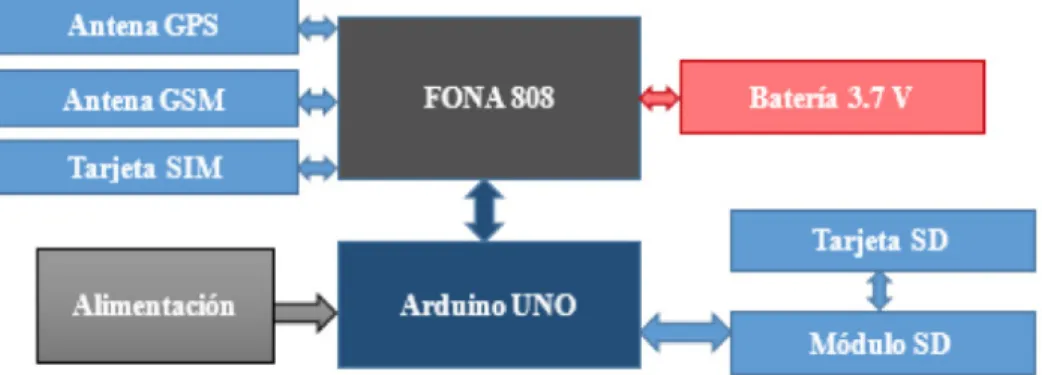
(5) Architecture based in open source hardware and software for designing a real time vehicle tracking device. Sistemas & Telemática, 16(44), 49-61.. Para la interfaz con la red GSM y con los satélites GNSS se selecciona Adafruit FONA 808 - Mini Cellular GSM + GPS Breakout (Figura 2) porque: integra un receptor GPS con buena precisión (2.5 metros aproximadamente) e interfaz a la red GSM, con las bandas de frecuencia que existen en Cuba; permite llamadas de voz y el envío y recepción de mensajes SMS, así como el envío y recepción de datos GPRS (HTTP, MMS, TCP/IP, etc.); posee interfaz serie para los comandos AT (instrucciones codificadas que conforman el lenguaje de comunicación con el módulo); y es compatible con cualquier Arduino (“Adafruit FONA...”, 2016). Para el almacenamiento local de la información se utiliza el módulo Adafruit de tarjeta SD/MicroSD (“SD card...”, 2016), que consiste en una placa que contiene la interfaz entre el socket de tarjeta SD y MicroSD a un encabezado estándar de 0.1’’ x 6 pines (Figura 3). Para la comunicación de FONA808 con los satélites GPS se utiliza una antena GPS pasiva de 50 Ω (“Passive GPS...”, 2016) y para la interfaz con la red GSM, una antena de Itead Studio de 15 g de peso y conector SMA a un cable uFL (“GSM antenna...”, 2016). Para la alimentación de FONA808 se utiliza una batería LiPoly de 3.7V 1200 mAh con conector JST de dos pines.. Figure 2. Adafruit FONA808. Figure 3. SD module. La arquitectura de hardware del dispositivo de rastreo propuesta se muestra en la Figura 4 y está basada en la arquitectura mostrada en la Figura 1. El componente principal lo constituye el módulo FONA808, cuya función es lograr la interfaz con los. III. Hardware and Software Architecture of the Device We propose the use of the Arduino open source hardware and software as our microcontroller unit, since it consists on a plaque including a microcontroller with all the necessary circuitry for its correct operation, it also has the technological requirements to process the GPS and GSM information, and it also has the necessary hardware for the connection to the corresponding input/outputs of the processor modules, sensors, and actuators that are part of the proposed system (“What is...”, 2016). For the GSM Network interface and the GNSS satellites, we selected the Adafruit FONA808 GSM + GPS breakout (see Figure 2) because it has a GPS receiver with good accuracy (2.5 meters approximately) and a GSM network interface with the frequency bands currently operating in Cuba. Also, the module allows voice calls and the sending of SMS messages and data via GPRS. It has a serial interface for the AT commands (coded instructions forming the communication language with the module) and it is also compatible with any Arduino (“Adafruit FONA...”, 2016). For the local storage of the information, we used the Adafruit SD/microSD module (“SD card...”, 2016), which consists on a board containing the interface between the SD socket to a standard header of 0.1” by 6 pins (Figure 3). The communication between the FONA808 with the GPS satellites employs a 50 Ω GPS passive antenna (“Passive GPS...”, 2016) and for the GSM interface, we used an Itead Studio antenna with an SMA connector to a uFL cable (“GSM antenna...”, 2016). The power supply of the FONA808 is provided by a LiPo battery of 3.7 V and 1,200 mAh with a 2-pin JST connector. The proposed hardware architecture of the tracking device is shown in Figure 4 andit is based on the general architecture displayed in Figure 1. The main component is composed by the FONA808 module, where its objective is to achieve the connection with the GPS satellites through the receiving antenna. Furthermore, that module must also achieve the GSM interface through the corresponding antenna and a SIM card providing the data service in the cellular network. Both antennas are connected to the FONA808 board via the uFL connectors, whilst the SIM card is put in the corresponding socket. The LiPo battery is connected via the JST connector; besides, this FONA808 module is connected with the Arduino via a se-. 53.
(6) Castillo, D., Martínez, S., & Gómez, A. (2018).. Figure 4. Hardware architecture of the device / Arquitectura de hardware del dispositivo. rial port. The SD module is able to communicate via the SPI protocol and it is directly connected to the Arduino. In the Arduino UNO (Figure 5), the device control application is running. It is programmed in the Arduino language (which is based on C++). Its corresponding flow diagram is shown in Figure 6. The program starts with a device configuration block. Firstly, the input/output pins of the Arduino are configured. We started in the serial hardware port, which serves to communicate a personal computer with the device. This process also initializes the SPI communication with the SD card and the serial port communication implemented from the software with FONA808. The FONA808 is initialized and the device configuration values are loaded from the EEPROM. Besides, the default device configuration values (administrative number, SIM card unlock code, GPS connection times, sending of the frame via the mobile network, and maximum speed) are also initialized and, consequently, the SIM card is unlocked. After the configuration, the program executes an infinite cycle, which is divided in several subroutines. The consulting subroutine towards the FONA808 device initially consults about the presence of SMS or call notificationson its serial port. In case of receiving a positive response, it reads the received text chain and it identifies the notifica-. Figure 5. Arduino UNO. 54. satélites GPS, a través de la antena receptora, y la interfaz con la red GSM, a través de la antena GSM y una tarjeta SIM, que provee el servicio de usuario de la red móvil. Ambas antenas se conectan a la placa FONA808 por los conectores uFL, la tarjeta SIM se coloca en el puerto localizado en la parte trasera y la batería LiPoly se conecta por el conector JST. Además, este módulo se conecta al Arduino vía puerto serie. El módulo SD se comunica por protocolo SPI y se conecta directamente al Arduino. En el Arduino UNO (Figura 5) corre el aplicativo de control del dispositivo, programado en lenguaje Arduino (basado en C++). Su diagrama de flujo se muestra en la Figura 6. El programa inicia con un bloque de configuración del dispositivo, se configura, en primer lugar, los pines de entrada/ salida del Arduino; se inicia el puerto serie de hardware, que servirá para la comunicación con una computadora personal; inicializa la comunicación SPI con la tarjeta SD y la comunicación del puerto serie implementado desde software con FONA808; se inicia el módulo FONA808; se cargan, desde la EEPROM, los valores de la configuración del dispositivo por defecto (número del administrador, código de desbloqueo de la tarjeta SIM, tiempos de encuesta al GPS y envío de la trama por la red móvil y velocidad máxima) y se desbloquea la tarjeta SIM.. Figure 6. Flow diagram of the main program / Diagrama de flujo del programa principal. http://www.icesi.edu.co/revistas/index.php/sistemas_telematica.
(7) Architecture based in open source hardware and software for designing a real time vehicle tracking device. Sistemas & Telemática, 16(44), 49-61.. Luego de la configuración, el programa ejecuta un ciclo infinito, el cual está dividido en varias subrutinas. La subrutina de encuesta a FONA808 inicialmente consulta por la presencia de notificaciones de SMS o llamadas en su puerto serie. En caso positivo, lee la cadena de texto recibida e identifica el tipo de notificación. Si se recibe una llamada telefónica, cuelga inmediatamente; si se recibe un mensaje de texto, se comprueba que provenga del número del administrador y que sea un mensaje válido que contenga datos útiles para la configuración del programa, de lo contrario, se ignora. A través de este mensaje el administrador puede cambiar todos los parámetros de la configuración del dispositivo desde una aplicación Android destinada para ello. Al final de la subrutina se elimina el mensaje recibido. La subrutina de encuesta a PC comienza estableciendo la comunicación serie válida solamente con una aplicación destinada para ello, a través de un proceso de autenticación. En caso contrario, se ignorará cualquier dato recibido por el puerto serie. Desde dicha aplicación se configuran los parámetros por defecto del dispositivo que se guardarán en la EEPROM. También se podrá controlar y configurar el dispositivo en funcionamiento y enviar información a la PC. Todas las tramas que se envíen entre el dispositivo, el software de PC y la aplicación en la estación base cumplen con la estructura que se muestra en la Figura 7. Los campos son: • Encabezado (3 bytes): 0xCC 0xCC 0xCC. • Tipo de mensaje (1 byte): información, control, configuración o alarma. • Datos (tamaño variable según el tipo, restringido a 135 bytes para un SMS). • Checksum: suma de chequeo (método de comprobación de errores). tion type. If a phone call is received, the system automatically hangs up; if a text message is received, it checks if it comes from the administrator number and it also check it has useful data for the program configuration. In case neither of both options are complied, the message is ignored. Through this message, the administrator can change all the device configuration parameters from an Android application destined for it. At the end of the subroutine, the received message is eliminated. The subroutine of consulting to a PC starts by establishing the serial communication only valid with a destined application for it through an authentication process. In other case, any data received in the serial port will be ignored. From this application, the device default parameters are configured and they will be stored in the EEPROM. Furthermore, it is possible to control and configure the device while it is operating and the sending of information to the PC is also feasible in this mode. All the frames sent between the device, the PC software, and the application in the base station comply with the structure shown in Figure 7. The fields are: • Header (3 bytes): 0xCC 0xCC 0xCC. • Message type (1 byte): information, control, configuration, or alarm. • Data (variable size as per the type, restricted to a maximum of 135 bytes for an SMS). • Checksum: error verification method.. Figure 7. Frames format (within brackets, the size in bytes of each field) / Formato de las tramas (entre corchetes el tamaño en bytes de cada campo). La subrutina GPS se ejecuta cuando está habilitada y según el periodo configurado. Primero se chequea el estado del posicionamiento o “Fix” del GPS, que puede ser “No Fix” cuando el GPS todavía no brinda una localización válida, “2D Fix” o “3D Fix”. Luego, se pide a FONA808 la trama con la información GPS que se guarda en una variable local, a partir de la cual se extraen los parámetros: hora UTC, latitud, longitud, velocidad (en km/h), altura (en metros sobre el nivel del mar) y curso (en grados). Estos datos se codifican y se guardan en la memoria del dispositivo (tarjeta SD) en tramas (registros) de 27 bytes llamadas GPSIF. El archivo donde se guardan los registros tiene extensión .log y su nombre se genera a partir de la fecha obtenida. Además, se envía un mensaje de alarma instantáneamente, al detectar un exceso de velocidad, si el usuario así lo desea. La subrutina GSM se ejecuta cuando está habilitada y según el período configurado. En ella se codifica el mensaje de texto,. The GPS subroutine is executed when it is enabled and it depends on the configured period. First, the positioning state (fix) of the GPS is checked; this can be “No Fix” when the GPS does not provide a valid location, “2D Fix” or “3D Fix” when the location is accurate. After, the frame with the GPS location is requested to the FONA808, which is stored in a local variable. From here, the following data are extracted: UTC time, latitude, longitude, speed (in km/h), height (in meters above sea level), and course (in grades). These data are coded and stored in the device memory (SD card) in frames (registers) of 27 bytes in size, named GPSIF. The file where the registers are stored has “.log” extension and its name is generated from the current date/time. Besides, if the user requires, an alarm message can be immediately sent if the system detects a speed excess in the automobile. The GSM subroutine is executed when it is enabled and as per the configured period. Within it, the SMS/ MMS message is configured as per the selected options. 55.
(8) Castillo, D., Martínez, S., & Gómez, A. (2018).. by the user and it is sent to the base station. First, the GSM signal intensity is checked [RSSI, Received Signal Strength Indication] and, if it is under -90 dBm (minimum value as per the manufacturer to detect signals and correctly send data) the current frame is queued in the “frames to be sent” queue. If a good signal is received later, the current GPSIF frame and all the other queued are introduced in the text message data field. An SMS can contain up to 5 GPSIF frames and many messages as required will be sent (in an MMS, up to 37 frames can be sent). Once the data field and the message are formed, the checksum is calculated and the message is sent to the administrator phone number. We also developed a simple software for PC using open source libraries for Qt Creator. This software can communicate with the serial port of the device and it has a graphical user interface [GUI], easing the user manipulation and the entering of the device default data. It is also possible to control the operation, receive and process information. As the software in the base station, we developed an application for the Android platform using Android Studio. This application provides a GUI that, essentially, allows to decide and visualize the data with the GPS information received from the tracking device; it also allows the control of the device remotely.. SMS o MMS de acuerdo con lo seleccionado por el usuario y se envía hacia la estación base. Primero se chequea la intensidad de la señal GSM recibida [RSSI, Received Signal Strength Indication] y, si se encuentra por debajo de -90 dBm, según especifica el fabricante (“Adafruit FONA...”, 2016), como mínimo para correcta transmisión de datos, la trama actual se añade a la cola de tramas por enviar; si se obtiene una señal buena, se añade la trama GPSIF actual y todas las que estén en cola dentro del campo de datos del mensaje de texto. Un SMS admite hasta cinco tramas GPSIF por mensaje, y se enviarán, tantos SMS, como sean necesarios (en un MMS de 1kB pueden enviarse hasta 37 tramas). Una vez conformado el campo de datos y el tipo de mensaje, se computa la suma de chequeo y se envía el mensaje al teléfono del administrador. Se desarrolló además un software sencillo en la plataforma para PC software libre y código abierto Qt Creator. Ella se comunica por puerto serie con el dispositivo y cuenta con una interfaz gráfica, con facilidades para el usuario, que le permiten introducir los parámetros por defecto del dispositivo, controlarlo en funcionamiento, recibir información y procesarla. Como software de la estación base, se desarrolló una aplicación para la plataforma Android utilizando Android Studio. Ella provee una interfaz gráfica que, esencialmente, permite decodificar y visualizar los datos con la información GPS recibidos desde el dispositivo de rastreo y el control del dispositivo vía remota.. IV. Resultados y discusión. Los componentes de hardware seleccionados, con las conexiones correspondientes y las tarjetas SIM y SD insertadas, se muestran en la Figura 8, y constituyen el dispositivo prototipo con el que se realizaron las pruebas. IV. Results and Discussion Funciona de la siguiente forma: antes de inicializar el dispoThe selected hardware components, together with the sitivo deben configurarse, a través del software de PC, los parámetros de funcionamiento por defecto, principalmente el núcorresponding connections and SIM/SD cards insermero de teléfono del administrador y el PIN para desbloquear ted are shown in Figure 8. They form the prototype la tarjeta SIM. Esto se realiza mediante puerto serie sobre la employed for the testing. conexión física a la PC, desde el puerto USB del Arduino. It works as follow: before the initialization of the device, Una vez configurado el dispositivo, está listo para funcionar it must be configured through the PC software. The data de manera independiente. Al energizarse, el Arduino ejecuta la to configure are mainly the default working parameters subrutina de configuración inicial descrita en la sección III, dejando activo el módulo FONA808. Luego, el programa ejecuta (i.e., the administrator phone number and the PIN to unel ciclo infinito y espera por las lock the SIM card). This is perforórdenes que se envíen por el med via the serial port using the usuario administrador a través physical connection with the PC de la red celular, tantas veces and from the Arduino USB port. como desee (encender/apagar GPS, habilitar/deshabilitar el Once the device is correctly envío de la información por configured, it is ready to operate la red celular y las opciones independently. When the power de configuración). Además, is on, the Arduino executes the puede ser controlado desde la initial configuration subroutine aplicación en PC si se encuentra conectado físicamente. La described in Section III, leaving información GPS se grabará the FONA808 module active.Afencriptada en la tarjeta SD y Figure 8. Prototype device / Dispositivo prototipo. ter that, the program executes the. 56. http://www.icesi.edu.co/revistas/index.php/sistemas_telematica.
(9) Architecture based in open source hardware and software for designing a real time vehicle tracking device. Sistemas & Telemática, 16(44), 49-61.. quedará disponible para un procesamiento diferido. Además, se enviará, si el usuario lo desea, al teléfono del administrador, donde se ejecutará la aplicación de monitoreo que permite el procesamiento de los datos en tiempo real. Para comprobar la efectividad del dispositivo se realizó un primer experimento con el objetivo de evaluar el procesamiento de los datos de la memoria SD de forma diferida y la precisión de los datos GPS. El dispositivo se instaló dentro de un vehículo Peugeot 205, se energizó desde una computadora portátil y se activó la subrutina de encuesta al GPS desde la aplicación de PC. Los datos fueron procesados posteriormente desde la misma aplicación. Se recorrió dentro de la Universidad Central “Marta Abreu” de Las Villas [UCLV], desde la Facultad de Ingeniería Eléctrica [FIE], al motel Los Sauces, y de regreso a la FIE, y se encuestó el GPS cada diez segundos. El arranque en frío del GPS tomó 40 segundos aproximadamente; se procesaron 80 tramas GPS, de las cuales se perdieron cuatro durante el arranque del GPS. En la Figura 9 se muestra el mapa con las ubicaciones, junto con la velocidad (en km/h) procesadas en Google Maps (tramo Los Sauces - FIE). Aquí se observa que el error de la localización es del orden de pocos metros. Se comparó visualmente la velocidad del vehículo con la enviada desde el dispositivo al monitor serie en la PC y se obtuvo una coincidencia de 100%, con un error no mayor a 1 km/h. Se consumió menos de 2% de batería. Se realizó un segundo experimento para evaluar el procesamiento de los datos en la variante de tiempo real. El dispositivo se instaló dentro del vehículo, se energizó desde una computadora portátil y se activó la subrutina de encuesta al GPS, desde la aplicación Android instalada en el teléfono del administrador. La subrutina GSM se activó tras recibir la primera trama GPS válida. Los datos fueron recibidos y desencriptados continuamente en la misma aplicación y quedaron además guardados en la memoria del dispositivo.. infinite cycle and wait for the orders sent by the administrator user via the cellular network. These orders can be sent as many times as the administrator desires (turn on/off the GPS, enable/disable the information sending via the cellular network, and change the configuration settings). Additionally, the device can be controlled from the PC application if it is physically connected to it. The GPS information will be stored and encrypted in the SD card and it will be available for further processing. Also, the system can send the information to the administrator phone number (if desired), where the monitoring application will start, allowing the data processing in real-time. In order to ensure the effectiveness of the device, we performed a first experiment with the aim to assess the data processing in the SD card in a differed manner, together with the precision of the GPS data. The device was installed inside a Peugeot 205 vehicle, we powered it from a laptop computer, and we activated the GPS consulting subroutine from the PC application. The data were processed afterwards from the same application. We did a test drive inside the Universidad Central “Marta Abreu” of the Las Villas [UCLV], starting from the Electric Engineering Faculty [FIE, Facultad de Ingeniería Eléctrica] to the Los Sauces hotel. It was a round-trip and the GPS was consulted each 10 seconds. The cold start of the GPS took 40 seconds approximately and a total of 80 GPS frames were processed, where 4 were lost during this cold start. Figure 9 shows the map of the locations, together with the speed (km/h) processed in Google Maps (Los Sauces – FIE trip). Here, it is possible to observe that the localization error is only in the order of a few meters. We visually compared the speed of the vehicle with the sent from the device towards the PC and we had a coincidence of 100%, with an error not larger than 1 km/h. The battery usage was only 2%. We performed a second experiment to assess the data processing in the real-time variant. The device was installed inside the vehicle, we powered on from a computer and we activated the GPS consulting subroutine from the Android application installed in the administrator phone. The GSM subroutine was activated after receiving the first valid GPS frame. The data were continuously received and unencrypted in the same application and they were stored in the device memory.. Figure 9. Sample of the obtained locations in the first experiment / Muestra de ubicaciones obtenidas en el primer experimento (Google Maps). We did a test trip between Yaguajayup to the UCLV via the north circuit (see Figure 10), consulting the. 57.
(10) Castillo, D., Martínez, S., & Gómez, A. (2018).. GPS each 30 seconds and sending the frames via SMS each 2 minutes. 44 locations were sent to the device in 27 SMS, all of them were received by the base station. From these numbers, 17 locations were queued in the zones without mobile coverage. Zero frames were lost and the battery use was less than 5%. The price in dollars of all the components in the device was U$ 97, this value can be slightly different according with the SD capacity. The cost for license payments for both hardware and software was null, since all the used components are open source. The mobile network usage cost depends on the SMS and MMS rates, being $0.09 CUC (Cuban Convertible Peso, where 1 CUC equals 1 US dollar) and $0.01 CUC per kB as per ETECSA (2016); although, the offered data plans by the carrier can be employed to reduce even more this cost. As per González Suárez et al., (2016), Cuba has saved 156,558.3 tons of fuel (around U$ 128 million) only with the variant related with the differed way to track vehicles. The designed device in the present research paper can operate in both operation modes: either differed or real-time. With the real-time control, the impact of saving fuel is potentially larger, although an exact value of the savings is complex to be estimated, since this variant is still widely not implemented in Cuba. In spite of this, it is possible to infer that, with a real-time control of the fleet where the position, speed, and course of the vehicles is well known, it is feasible to achieve a total control of the routes logistics and deliveries in the administrative side. Furthermore, the number of unnecessary trips and kilometers will be reduced, since there is the option to plan the route more efficiently. Events, such as speed excess, non-allowed stops, and changes in the route can be detected to take the pertinent actions, avoiding accidents, robbery, and unnecessary fuel and resource spending.. Se recorrió desde Yaguajay hasta la UCLV por el Circuito Norte (Figura 10), encuestando el GPS cada 30 segundos y enviando las tramas por SMS cada dos minutos. Se enviaron por el dispositivo 44 localizaciones en 27 SMS, todos recibidos por la estación central, de las cuales 17 habían sido puestos en cola en las zonas sin cobertura. No se perdió ninguna trama y se consumió menos de 5% de batería. El precio en dólares (US$) de todos los componentes del dispositivo asciende a US$97, valor que puede variar de forma mínima, de acuerdo con la capacidad de la tarjeta SD. El costo por pago de licencias de uso de los componentes de software o de hardware es nulo, debido a que todos constituyen hardware y software libre. El costo de explotación depende de las tarifas de SMS y MMS, $0.09 CUC y $0.01CUC por 1 kB, según ETECSA (2016), aunque se pueden aprovechar los planes que esta ofrece. Según González Suarez et al., 2016), Cuba ha ahorrado, hasta 2015, 156.558.29 toneladas de combustible (alrededor de US$128.718.784,30) solamente con la variante de forma diferida de rastreo de vehículos. El dispositivo diseñado en el presente trabajo puede funcionar, tanto en modo diferido, como en tiempo real. Con el control en tiempo real el impacto es aún mayor, aunque una cifra exacta del ahorro es compleja de estimar debido a que esta variante no se ha implementado en Cuba de forma generalizada. A pesar de esto se puede afirmar que, con un control de flota en tiempo real, donde se conoce en cada momento la localización, velocidad y curso de los vehículos que la componen, se logra un control total de la logística de rutas y entregas por parte de la administración. Además, disminuye el número de viajes y de kilómetros innecesarios, al tener la posibilidad de planificar la ruta más eficiente. Se puede detectar en el momento de su ocurrencia situaciones como excesos de velocidad, paradas indebidas y desvío de las rutas programadas, y tomar las acciones pertinentes para evitar accidentes, hechos delictivos y los gastos de combustible y recursos que surgen como consecuencia. Es importante señalar que el dispositivo diseñado constituye un producto nacional, que cumple con las funcionalidades básicas de los dispositivos similares analizados en la sección II, adecuado a las características de Cuba. Además, queda apto para ampliar sus potencialidades, con la adición de nuevos elementos de hardware y la extensión de las capacidades del software. De esta forma se contribuye a la política de la susti-. Figure 10. Locations of the Caibarién-UCLV trip obtained via SMS / Ubicaciones del tramo Caibarién-UCLV obtenidas por SMS (Google Maps). 58. http://www.icesi.edu.co/revistas/index.php/sistemas_telematica.
(11) Architecture based in open source hardware and software for designing a real time vehicle tracking device. Sistemas & Telemática, 16(44), 49-61.. tución de importaciones de equipos similares. Queda claro el impacto medioambiental debido al ahorro de combustible que se puede lograr y a la correspondiente cantidad de gases no emitidos a la atmósfera debido a la combustión.. V. Conclusiones A partir de tecnologías que costituyen hardware y software libres es posible y viable diseñar la arquitectura de un dispositivo de rastreo de vehículos que permita el control de flota en tiempo real y de forma diferida, mediante una solución de factura nacional. La placa microcontroladora Arduino UNO y el módulo Adafruit FONA808 constituyen las tecnologías más adecuadas, entre las variantes analizadas, para el diseño de un dispositivo según las condiciones de Cuba. Con la arquitectura de hardware diseñada se garantiza la interconexión exitosa entre todos los componentes que conforman el dispositivo. La arquitectura de software propuesta garantiza su correcto funcionamiento, debido a que permite la obtención de la información GPS precisa, su encriptación, almacenamiento local, su envío a través de la red celular y la flexibilidad en cuanto a la configuración de los parámetros. El sistema de comunicación garantiza la seguridad y fiabilidad de todo el sistema a partir de la autenticación de la comunicación entre el dispositivo y las aplicaciones de configuración y monitoreo, la encriptación de la información y la codificación de las tramas según el protocolo entendible solamente por el sistema. Las pruebas experimentales realizadas demostraron la efectividad de la arquitectura de hardware y software propuesta, al cumplir con los requisitos de funcionamiento, configuración, flexibilidad y seguridad que caracterizan un dispositivo de rastreo de vehículos en tiempo real y, por tanto, permite a la empresa que lo aplique la reducción de los costes de logística y de mantenimiento, un mayor ahorro de combustible y la prevención de violaciones por parte de los conductores.. It is important to focus that the designed device was planned as a national device, complying the basic functionalities of the devices analyzed in Section II and suitable for the Cuban environment. Additionally, it is possible to enhance its features with the addition of new hardware elements and the improvement of the software capabilities. Consequently, we contribute to the policy of reducing the importing of similar finished devices. The environmental impact of our prototype is clear, since the fuel saving that can be achieved is relevant due to the fact that the greenhouse gases emitted to the atmosphere will be reduced with more efficient routes for the fleets.. V. Conclusions From several technologies employing open source hardware and software, it is posible –and feasible– to design the architecture of a vehicle tracking device that allows the real-time and differed fleet control; this, via a solution created in, and for Cuba. The Arduino UNO development board and the Adafruit FONA808 are amongst the most suitable technologies for the design of this device, as per the Cuban conditions. With the designed hardware architecture, we guarantee the successful connection between all the components making the device. The proposed softwarearchitecture also guarantees its correct operation, since it allows the gathering of accurate GPS information, its corresponding encryption and frame coding as per the protocol –understandable only by the system itself–. The communication system ensures the safety and reliability of the whole system through the communication authenticationbetween the device and the monitoring and configuration applications. The information encryption, and the frame coding understandable only by the system also guarantess acceptable levels of data security. The performed experimental tests demonstrated the effectiveness in the proposed hardware/software architecture, by complying the operational, configuration, flexibility, and safety requirements which characterize the real-time vehicle tracking devices. Hence, the companies using these devices will reduce their logistics and maintenance costs, allowing larger fuel savings, and avoiding unexpected behaviors from the drivers.. 59.
(12) Castillo, D., Martínez, S., & Gómez, A. (2018).. References / Referencias Adafruit FONA 808 - Mini Cellular GSM + GPS Breakout (2016). Retrieved from: https://www.adafruit.com/product/2542 Empresa de Telecomunicaciones de Cuba [ETECSA]. (2016). Telefonía Móvil. Retrieved from: http://www.etecsa.cu/telefonia_movil/ Fleischer, P. B., Nelson, A. B., Sowah, R. A. & Bremang, A. (2012). Design and development of GPS/GSM based vehicle tracking and alert system for commercial inter-city buses. In: 2012 IEEE 4th International Conference: Adaptive Science & Technology (ICAST). IEEE. doi:10.1109/ICASTech.2012.6381056 González Suárez, G., Iglesias, R. C., Fernández, J. L. C., Rosales, J. D. F., Domínguez, M. B. ... & Monteagudo, L. R. (2016). Movilweb, diez años de control de flotas en Cuba. In: Informática 2016. XVI Convención y Feria Internacional. Retrieved from: http://www.informaticahabana.cu/sites/default/files/ponencias/GEO044.pdf GSM antenna with interface cable (short & SMA plug straight angle). (2016). Retrieved from: https://www.adafruit.com/ products/1859 Jian-Ming, H., Jie, L. & Guang-Hui, L. (2012). Automobile anti-theft system based on GSM and GPS module. In Intelligent Networks and Intelligent Systems (ICINIS), Fifth International Conference. IEEE. doi:10.1109/ICINIS.2012.86 Passive GPS Antenna uFL - 15mm x 15mm 1 dBi Gain. (2016). Retrieved from: http://adafru.it/2461 Ramani, R., Suthanthiravanitha, S. V. H., Selvaraju, S., & Thiruppathi, M. (2013). Vehicle tracking and locking system based on GSM and GPS. I.J. Intelligent Systems and Applications, 9, 86-93. SD card / microSD breakout module for Arduino, AVR, PIC, ARM,MSP430... (2016). Retrieved from: http://itead-europe.com Vázquez, C. R., Palacios, E. F., Córdova, L. S. & Romero, M. (2016). Dispositivo de adquisición y transmisión de la posición de un vehículo mediante GPS y Wi-Fi. RIELAC Revista de Ingeniería Electrónica, Automática y Comunicaciones, 37, 15-27. Verma, P. & Bhatia, J. S. (2013). Design and development of GPS-GSM based tracking system with Google map based monitoring. International Journal of Computer Science, Engineering and Applications (IJCSEA), 3, 33-40. What is Arduino. (2016). Retrieved from: http://www.arduino.cc/. 60. http://www.icesi.edu.co/revistas/index.php/sistemas_telematica.
(13) Architecture based in open source hardware and software for designing a real time vehicle tracking device. Sistemas & Telemática, 16(44), 49-61.. CURRICULUM VITAE Diony Roely Castillo Rodríguez He has a Gold Degree in Automatic Engineering from the Universidad Central de Las Villas [UCLV] (Cuba, 2017). He works as a graduate in training at the Automation and Computer Systems Department (Faculty of Electrical Engineering – UCLV). He researches in application of free hardware and software technologies and artificial intelligence applied to the solution of practical problems, such as the management and control of vehicle fleets and precision agriculture. His research has won prizes at the Science and Technology Forum and has been presented at events, such as the 2017 UCLV International Convention / Graduado con Título de Oro de Ingeniería Automática en la Universidad Central de Las Villas [UCLV] (Cuba, 2017). Se desempeña como graduado en adiestramiento del Departamento de Automática y Sistemas Computacionales de la Facultad de Ingeniería Eléctrica en la UCLV. Desarrolla investigación en la aplicación de tecnologías de hardware y software libres e inteligencia artificial a la solución de problemas prácticos como la gestión y el control de flotas de vehículos y la agricultura de precisión. Sus investigaciones han obtenido premios en el Fórum de Ciencia y Técnica y se han presentado en eventos, como la Convención Internacional UCLV 2017.. Alain Sebastián Martínez Laguardia Ingeniero en Automática y Máster en Telemática de la Universidad Central “Marta Abreu” de Las Villas [UCLV] (Cuba, 2001 y 2005, respectivamente), con un doctorado conjunto en Ingeniería entre la Université libre de Bruxelles (Bélgica) y la UCLV (2015). Desde 2001 es miembro del Departamento de Automática y Sistemas Computacionales de la UCLV, donde actualmente es profesor titular y jefe del departamento. Imparte docencia en varios campos de la disciplina de Computación-Programación. Fundador del Grupo de Automatización, Robótica y Percepción, desde 2003 investiga en el diseño de sistemas empotrados y el desarrollo y aplicación de vehículos autónomos. Ha participado en varios proyectos de investigación internacionales / Engineer in Automation and Master in Telematics from the Central University "Marta Abreu" of Las Villas [UCLV] (Cuba, 2001 and 2005, respectively), with a Ph.D., in Engineering (Université libre de Bruxelles, Belgium and the UCLV, 2015). Since 2001 he is a member of the Automation and Computer Systems Department of the UCLV, where he is currently a full professor and head of the department. He teaches in several fields of the computer-programming discipline. Founder of the Automation, Robotics and Perception Group, since 2003 he has been researching the design of embedded systems and the development and application of autonomous vehicles. He has participated in several international research projects.. Alberto Gómez Abreu Engineer in Automatic Control of the Universidad Central "Marta Abreu" de Las Villas [UCLV] (Cuba, 1994) and Master of Science, Management of Science and Innovation of the Instituto Superior de Tecnologías y Ciencias Aplicadas (Havana-Cuba, 2010 ). His experience, as a specialist in automation, includes: bioplants, the factory of solar heaters and heat exchanger batteries RENSOL and the Empresa de Servicios Informáticos de Ciego de Ávila (Cuba). He has developed fourth generation temporary immersion bioreactors in Cuba, Costa Rica and Mexico / Ingeniero en Control Automático de la Universidad Central “Marta Abreu” de Las Villas [UCLV] (Cuba, 1994) y Maestro en Ciencias, Gerencia de la Ciencia y la Innovación del Instituto Superior de Tecnologías y Ciencias Aplicadas (La Habana-Cuba, 2010). Tiene experiencia, como especialista en automatización, en bioplantas, la fábrica de calentadores solares y baterías intercambiadoras de calor RENSOL y la Empresa de Servicios Informáticos de Ciego de Ávila (Cuba). Ha desarrollado biorreactores de Inmersión Temporal de cuarta generación en Cuba, Costa Rica y México.. 61.
(14)
Figure


Documento similar