Costa Rica Institute of Technology
Electronics Engineering School
Design and implementation of a 6 degrees of freedom
controller
for the GRACE system
A thesis submitted in fulfillment for the
degree of Licenciate in Electronics Engineering
Supervisor: Prof. dr. eng. Mauricio Muñoz-Arias
Declaration of authenticity
I, the undersigned, William Retana Calvo, declare that the dissertation is my original work, gathered and utilized especially to fulfil the purposes and objectives of the study, and has not been previously submitted to any other university for a higher degree. I also declare that the publications cited in the work have been personally consulted.
William Retana Calvo.
ID:114990765
Abstract
In this thesis, the reader can obtain information about the 3D robotic scanner of Groningen University. The design process including the PCB and the 6 Degrees of freedom control for the movements, also how the light is regulated in order to provide accurate data with an algorithm and a constant current power supply is shown in the document. The implementation and results are shown therefore the reader can analyze the materials and methods for further projects.
Resumen
En esta tesis el lector podrá obtener información sobre el escáner 3D de la Universidad de Groningen. El proceso de diseño incluyendo el PCB y el control para el sistema con 6 grados de libertad, así como la luz que es regulada para tener datos limpios utilizando un algoritmo y una fuente de corriente constante es mostrado en el documento. La implementación y resultados son mostrados, así entonces el lector puede analizar los materiales y métodos para futuras aplicaciones.
Dedication
To my parents: Julieta Calvo and William Retana, for all their effort on having me here, for all the sacrifices that they had to make to see me as a professional person. All my success is because of them. Also, to my brother Jorge Retana for his support all this years and to my sister Rebeca. I cannot finish without mentioning my grandparents: Hilda, Carmen, and Juan Rafael, who gave me a place to stay when I needed. Finally, to my cousin Walter Retana and his wife Cristina Mora, for having me as a member of their family, as well as to my uncle Henry Retana.
I cannot be more thankful with my life, my teachers, classmates, and friends. This is the end of a life chapter, but the beginning of others, thank you all.
Appreciation
I thank Dr. Ing. M. Muñoz-Arias for being my support in the project, for giving me the technical guidance and the opportunity of going to the Netherlands. Also, to Prof. Dr. D. G. Stavenga, for accepting me to do my final graduation project in the Groningen University. Also, to the Instituto Tecnológico de Costa Rica which supported my project. Finally, to the EDUNAMICA association which completed the economical support.
6.1.2 Selected driver . . . 30
IV Conclusions and recommendations
73
12 Conclusions and recommendations 75
12.1 Conclusions . . . 75 12.2 Recommendations . . . 75
A acronyms 77
Bibliography 79
10.4 2D image with clipping . . . 61
10.5 3D image with clipping . . . 62
10.6 Real image with no clipping . . . 63
10.7 2D image with no clipping . . . 63
10.8 3D image with no clipping . . . 64
11.1 XYZ system for the Motor movements . . . 65
11.2 Spherical plane for the elevation an azimuth movements . . . 66
11.3 Elevation an azimuth motors in the system . . . 67
11.4 Hardware functionality diagram . . . 68
11.5 Hardware Connection for the system . . . 68
11.6 Enable mode control . . . 70
11.7 Software action control diagram . . . 71
List of Tables
6.1 Wantai motor Electrical Characteristics. . . 29
6.2 Principal Characteristics of the stepper drivers. . . 29
6.3 Micro-controller comparison table. . . 33
7.1 Stepper motor electrical characteristics. . . 35
7.2 Step resolution. . . 36
7.3 TRQ values for current limiting. . . 37
7.4 Minimum and Maximum steeping time. . . 39
7.5 Input voltage variation for the LED using FemtoBuck LED Driver. . . 40
7.6 PWM light intensity cycle. . . 42
9.1 Devices sizes and numbers. . . 50
9.2 Required information for path width calculation. . . 51
9.3 PCB path width. . . 52
11.1 Power current for each stepper motor . . . 69
Part I
Chapter
1
Introduction
Biology and nature have made an import contribution in the human race advance. Medicine, military technology, transportation, entertainment are a just few of the examples in which nature provides an important part of the advance of the technologies. Navigation systems like drones and rescue robots are possible thank to the compound eye studies.
To make this studies, it is necessary the collaboration among different science areas. In the GRACE project engineers and scientist have collaborated. The First control implementation of the GRACE mechanical system was developed by, [4], using an algorithm developed by [3], the system has made improvements, the last is made by [5] who made an image stitching algorithm for compound vision research.
The main objective of the project is to design a new controller for the 6 degrees of freedom sys-tem that is going to be used in the compound vision research. Selecting the hardware in an accurate way provides a better functionality; the process of the hardware selection is discussed. The control also includes a LED controller which regulates the light intensity for the system. This light intensity is established by an auto clipping algorithm to provide the accurate data. The system must be in a PCB therefore, the design of the PCB is in the present document.
Chapter
2
Theoretical Framework
2.1
Pseudopupils of Compound Eyes
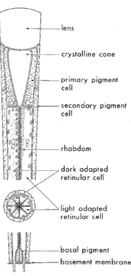
Figure 2.1: The ommatidium of a hymenopteran compound eye representing a typical apposition eye. Incident light is focussed by the dsoptrical apparatus (lens and crystalline cone) on the photopigment-containing rhabdom. In the dark-adapted state the rhabdom is surrounded by vacuoles which vanish upon light adaptation while retinular cell pigment granules then gather against the rhabdom. [2]
2.2
Deep Pseudopupil
The importance of knowing the deep Pseudopupil will be discussed on Section 2.3 which shows the optical functionality of the whole system.The distal plane of the retinula aligns with the focal plane of the ommatidium’s dioptric apparatus. This is called the deep pseudopupil and it can be seen from the outside using a microscope when the objective is longer than the space between the cornea and ommatidial axes intersection. This gives observers a way to study photoreceptor processes in live samples, [2]. In the experiment alive butterflies are used in order to provide clear data, when the butterfly die, the reflections are not longer good for take the information.
2.3
Reflections in the optical apparatus
In Section 2.2 the deep pseudopupil was introduced. In the current section, the optical functionality will be discussed. Also, the new optical system that creates the reflections to provide the data analysis is going to be shown. “Many insect species have a well-developed visual system with the capacity to see colour, i.e. objects in their environment are discriminated by their spectral content. Butter-flies are considered to be highly visual animals and are generally believed to possess colour vision” ,[1].
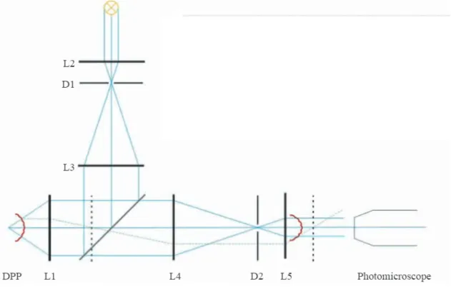
Figure 2.2 shows a modified epi-illumination microscope which is fundamental in the optics for the project.
Figure 2.2: Modified epi-illumination microscope. [1]
The general purpose of the lens and mirrors system is to reflect the interested light of the eye response in order to proceed to take a picture with the photo microscope. In order to create the reflection the apparatus has mirrors, diaphragms and lens to give an accurate result. The mirrors, diaphragms and lens are shown in Figure 2.2.
angle is needed between the L1 and L3 lens with a45◦ in order to reflect the light that comes from the L3 lens to the butterfly eye which is going to reflect it again, but due to the new angle it will cross the semi-reflecting mirror and reach L4 lens that is confocal with the L1 lens. Hence, the telescopic lens pair L1 and L4 images the deep pseudo pupil in the back focal plane of L4, where diaphragm D2 is positioned. The eye shine created by the reflection of the butterfly eye is finally imaged by lens L5, placed confocal with L4 and then, the picture can be obtained. To obtain an optimal picture, the areas of diaphragms D1 and D2 must be adjusted so that they are slightly wider than the image of the deep pseudo pupil.
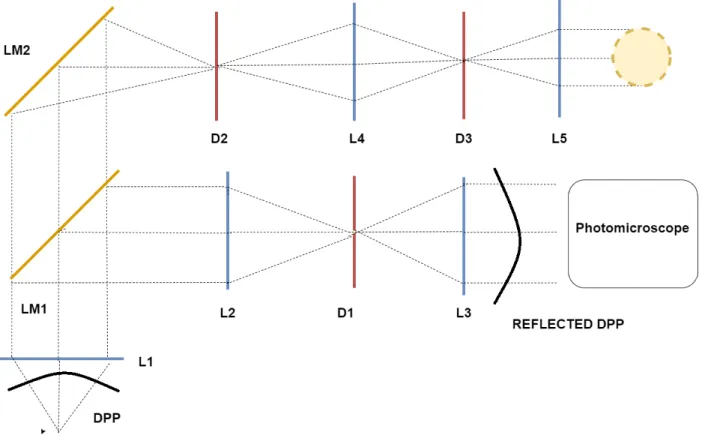
Due to the project resources, another epi-illumination microscope is designed. Figure 2.3 shows the new design, in which the functionality principle is similar as the previous one.
Figure 2.3: New epi-illumination microscope.The lenses and mirrors create a image of the butterfly eye that is used for the image data acquisition.emi-reflecting mirror are represented with a LM, lens with a L and diaphragms with a D
Chapter
3
Project Environment
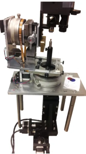
The project is part of the GRACE system at the University of Groningen, Netherlands. The main objective of the project is to get a better understanding of the eyes of arthropods, such as butterflies. The Computational Physics department of the University of Groningen is interested in the project because the butterfly eyes are compound structures. A compound Structure means that for example one eye is made of smaller eyes, called ommatidia. Each ommatidium is an independent visual system, with its own photoreceptor cells ,[3]. In the project many stepper motors are used. Steppers allows all the movements of the mechanical system, the system is shown in figure 3.1. However, these steppers have to be controlled in an appropriate way. At the moment some students have been working on the 3D scanner and the steppers controllers. In the current system, the 3D robotic scanner can photograph the local reflection properties of the eyes of the butterflies at high magnification, so it can create a 3D image of the butterfly’s eye that is going to be used on the current studies of the visual systems of arthropods.
The scanner is compound by two parts that work synchronously. In the current system, the drivers that are used for controlling the steppers do not dissipate heat well. Therefore it is important to find new drivers to solve the problem taking into consideration that the controllers have to work synchronously. So, it will also be very important to define whether the controllers will continue using Arduino technology or another micro controller will be used.
controller to correct minor slip-ups.
Figure 3.1: Complete mechanical system of the GRACE system.
Chapter
4
Problem Definition
4.1
Analysis
Now, because the project environment is known, a problem can be established. Due to the heat dissipation of the drivers ,[7]. the technology that is used now must be analyzed, the system has 6 DOF (degrees of freedom)and each DOF use a a stepper motor, due to the steppers that are used the controller must be modified therefore it can be adjusted to the new drivers. Figure 4.1 shows the actual driver that is being used [7].
As was mentioned before, the main problem with the drivers is the heat dissipation, Figure 4.2 shows the power-temperature graphic of the EasyDriver, as it is shown on the graphic there are heat problems when the power dissipation reaches less than 2 Watts, thus the new drivers must tolerate better power dissipation than the ones currently being used, according to researchers the temperature reaches the 100 degrees Celsius, so the dissipation may be around 1 Watt, and that factor is the one to take in consideration when the new driver is going to be selected.
Once the drivers are selected, the actual controllers should be modified according to the new system specifications. Figure 4.3 shows the actual system diagram, as it is shown in the Figure, the micro-controller that is being used is the Leonardo Arduino, it has a 16 MHz clock, thus according to the new design the micro controller may be changed. The change is related, to the system velocity , the one that is being used has velocity that the actual controller can handle, regarding the new system velocity, new controllers must be taking in to consideration.
the servo motors based on the commands send by the PC, so it can control and regulate all the DOG of the system, using an algorithm that was created before by ,[4].
Finally there must be interaction between the controller and the gionometer, In the current sys-tem the interaction is not available by now. A High intensity LED is going to be used, therefore the controller must be designed. It is is very important regarding functionality of the images that are processed. Figure 4.4 shows an image with "clipping" it is is when the intensity of the LED is not in the accurate value, then there is data loss , [6].
Figure 4.1: EasyDriver functional Block diagram.
Figure 4.2: EasyDriver power-temperature graphic.
Figure 4.4: Image with clipping.Blue color represents low intensity of red light channel reflection, while yellow color high intensity
4.2
Synthesis
The GRACE system has problems with the current controller regarding dissipation and functionality. The stepper drivers are not working properly. Then, the drivers must be replaced and the controller has to be modified, designing also the LED controller that is missing to solve the clipping problem.
Chapter
5
Solution Focus
The solution of the problem is focused on the design, simulations, and testing using Mathlab and Arduino. It is because the system has already designs implemented on that technology. Therefore, if a change is needed, it would be faster to use the current technology than a new one. Modifying the design will be necessary and the components will be replaced according to the simulation and the results of the test. The communication between the system controllers must be accurate, so there is going to be testing of the communication system.
The design of the controller will be developed using Arduino and communicate with Mathlab. If the new components require other speeds of functionality, the technology might be modified. The speed of functionality is an important factor that must be taken into consideration for the design of the controller.
Part II
Chapter
6
Hardware Selection
6.1
Motor Drivers
According to the motors that are already working in the GRACE system, 3 options of drivers are evaluated. Since the motors are Wantai Mini Stepper, the motors specifications must be taking into consideration in order to select the accurate driver. Table 6.1 shows the stepper most relevant information.
Table 6.1: Wantai motor Electrical Characteristics.
Feature Value
Rated Voltage 3.1V Rated Current 2.5A
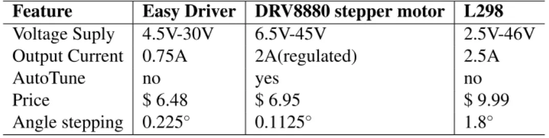
Table 6.2 shows the principal characteristics of the three drivers that are important for the project execution
Table 6.2: Principal Characteristics of the stepper drivers.
Feature Easy Driver DRV8880 stepper motor L298
Voltage Suply 4.5V-30V 6.5V-45V 2.5V-46V Output Current 0.75A 2A(regulated) 2.5A
AutoTune no yes no
Price $ 6.48 $ 6.95 $ 9.99
Angle stepping 0.225◦ 0.1125◦ 1.8◦
6.1.1
Driver selection analysis
work, 12V are enough for supply the motors, so all drivers are good for the voltage characteristics; however, the motor also needs 2.5A and that is shown in the second feature of Table 6.2. As it is shown there, only the L298 driver can supply that current; however, the DRV8880 has current limitations. It is important because it prevents possible equipment burning. The L298 does not have that feature and neither does the Easy driver. Despite 2.5A are needed to supply the Wantai steppers, the Wantai motor works fine with 0.75A, but it might end up not working well besides a reduced output power which affects torque/max speed, and the scanner needs as much torque as possible in order to work properly.
There is an important feature called AutoTune. Only the DRV8880 has that feature, so the de-signer does not have to take in consideration the decay of current waveform. In the Easy Driver and the L298 that option is not available. Consequently, the designer has to select the decay mode according to the desired system.
The economic factor is always an important point to take into consideration when engineers make an electrical design, at first instance in Table 6.2 there is no big price difference, but also the num-ber of devices take part in the selection. The GRACE system has 6 DOF and each DOF has its own motor that controls it, therefore 6 drivers are needed. When the number of devices are taking in consideration the Easy driver Price rises up to $38.88, the DVR8880 to $41.7 and the L298 to $59.94.
Finally the angle stepping that is different in each driver, it is better if the steep is short. Short steps provides better accuracy. And since the GRACE system has little movements the DVR88800 is the driver that works better in that case.
6.1.2
Selected driver
Once the information of every driver is analysed, the selected driver for the motor is the DRV8880 stepper motor, the main two factor for selecting the driver, were the current limiting and the autotune feature. AutoTune will automatically adjust the decay scheme based on operating factors like:
1. Motor winding resistance and inductance 2. Motor aging effects
5. Motor back-EMF difference on rising and falling steps 6. Step transitions
7. Low-current vs. high-current dI/dt
All that is important because it makes better current operation, therefore there are less heating problems and the system works better.
6.2
Light intensity control
As it was mentioned before, the hardware selection is of great importance. If the light intensity is not the accurate, the obtained data is not going to work, there are going to be bad images and when the digital image processing is done, the image is going to be discarded because of the moment. Two options are going to be analyzed in order to select the best hardware for the project.
6.2.1
Hardware Analysis
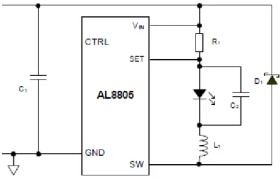
AL8805
The AL8805 is a step-down DC/DC converter designed to drive LEDs with a constant current, in a general perspective, it has a current control given by a voltage input wich gives the accurate amount of current that the LED can drive. Figure 6.1 shows the minimum electrical diagram for control the LED.
Figure 6.1: Electrical diagram for the AL8805.
component that includes the AL8805 device, therefore a PWM or an analog voltage are the only values needed for the control.
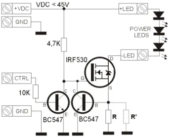
PWM using transistors
The controller is using transistor and resistors as it is shown in figure 6.2.
Figure 6.2: Electrical diagram for the PWM usin transistors
The driver in Figure 6.2 regulates the current through the LEDs connected through an N-channel MOSFET (IRF530) and a current sensor using a BC547 transistor and a resistor R. When the circuit is turned on, the transistor does not work and the “gate" receives a positive voltage through resistance of 4.7 K which makes driving. It turns on the LED and produces a voltage drop on the resistance R that is serial with the LED. If the current increases, the voltage drops across the resistor and exceeds the threshold voltage of the transistor base. Therefore, the gate voltage of the MOSFET decreases and reduces the LED current. As a consequence, the current on the LED depends on the value of the resistance.
6.2.2
Selected controller
Each controller regulates the current in an accurate way. Consequently, both can be implemented in the design for the 3D robotic scanner, since the important factor is the current regulation; however, the AL8805 in the PicoBuck is easier to use and it makes a better time management during the project execution, contrary to the PWM using transistors which has many components that have to be dimensioned according to the project specifications and it takes time to do it. Therefore, the AL8805 is selected.
6.3
Micro-controller
All the system for the 3D robotic scanner controls must have a micro-controller which provides the system with all the instructions that are going to be executed. In that case, there are the following requirements to be taking in to consideration to choose the micro-controller:
1. 36 digital outputs for the 6 driver control inputs
2. 2 analog outputs or or 2 PWM outputs for the LED intensity control
3. Digital signals for the RST of the arduino and the LEDs in order to provide the user an easy way of use.
4. USB access.
6.3.1
Comparison table
Table 6.3 shows the most relevant characteristics of 4 micro-controllers. Arduino Technology is used because of previous work that has been made and it saves time not changing the technology.
Table 6.3: Micro-controller comparison table.
Chapter
7
Use of selected Hardware for
implementation
7.1
Wantai Motors
The use of the motors has been selected due to the previous work done by researches of the Groningen University ,[4]. Therefore it is known that the torque and the speed of the motor are accurate for the GRACE system. However it is important for the propose of the project to take always in consideration the maximum current an voltage that the motor can drive without damage it. Table 7.1 shows the electrical characteristics of the two motor stepper use in the scanner.
Table 7.1: Stepper motor electrical characteristics.
Stepper motor model Rated Voltage(V) Rated Current(A)
42BYGHW811 3.1 2.5
42BYGHM809 3.06 1.7
The current values of the motor do not affect the driver selection, due to the maximum current that the driver supplies that is 1.6 A , if the current supply of a driver is higher that the motor rated current then a current limitation is necessary.
7.2
DRV8880
7.2.1
The driver
micro step function. Figure 7.1 shows the driver and the pin distribution that is going to be required for the PCB design.
Figure 7.1: Driver for the stepper motors.
7.2.2
Stepping
The current drivers that the 3D robotic scanner has can make up to 1/8 of micro stepping resolution. The DRV8880 can make up to 1/16 micro stepping resolution, therefore the control has to take the DRV880 resolution in consideration, and also it has to have the possibility of change the micro stepping according to a specific requirement for testing the system or changing the speed of the move of any DOF. Table 7.2 shows the steep resolution for each state of inputs.
Table 7.2: Step resolution.
Due to the actual size of the micro stepping all the system takes in consideration that the micro steps for complete a cycle that is 360◦are 800 since the motor has a resolution of 1.8◦ per step therefore it takes 200 steps to complete the cycle (360/1.8=200 steps), therefore for the proposed drivers the number of steps are 1600.
7.2.3
Current Limiting and use
Current limitation
The driver has the option of limiting the current, in cases of motors that drive less current than the one that the drivers provide the regulation must be done. The DVR8880 can supply up to 1.6A thus if a motor rated current is less than 1.6A the current limiting must be set up, the setting up is using equation 7.1 where the values of TRQ are shown in Table 7.3 and Vref is a Voltage value that can change according to a potentiometer in the driver.
Current= V ref ·T RQ
For example if a motor has a rated current on 1A, the Vref value is 1.32V due to the default value of TQR=1 that is 100% . Due to the rated current of the motors that is higher than the current supply of the driver, the current must be set to the maximal that the driver supply , the set gives a Vref of 2.12V using the default value of 100%.
Compare to the easy drivers used in the system that supplies up to 0.75A , the current use is more efficient in the DVR8880.
Another consideration of the use of current is that, the logical inputs in the design should be dis-connected to provide a 100% and it is useful due to the micro controller configuration, because there will be less logical inputs to control.
Auto Tuning
mode is necessary for make an efficient use of current. Figure 7.2, [8] shows how the current increases and decreases during the steps sequence.
Figure 7.2: Current increasing and decreasing due to stepping.
There is a deep explanation in ,[8]. about all the decay modes that the DVR8880 has, however in the project auto tune is selected.
“AutoTune greatly simplifies the decay mode selection by automatically configuring the decay mode between slow, mixed, and fast decay. In mixed decay, AutoTune dynamically adjusts the fast decay percentage of the total mixed decay time. The feature eliminates motor tuning by automatically determining the best decay setting that results in the lowest ripple for the motor” [8].
7.2.4
Driver Control
Step and direction
In order to control the steps a micro controller must be used, due to a typical way form that the driver step input requires in order to work properly. Figure 7.3 and Table 7.4 shows the step control minimum and maximum time that is required. It is necessary that the micro controller can be able to provide that time on its changes of outputs.
Figure 7.3: steeping time way form.
The direction of the steps is controlled by the digital input dir. Therefore, the direction of the motor rotation depends on the logic state of dir.
Enable
The DBR880 has two control enables: one is the digital input Enable and the other is the digital inputs nSleep. Enable can be disconnected and the driver is going to work. However, the enable can be connected to a digital input in order to turn on or off the driver.
The nSleep input control is the best option to control the driver due to its power save feature. This feature provides a very low quiescent current, [8].
7.3
FemtoBuck LED Driver
7.3.1
The driver
The driver uses the AL8805 ,[9], that basically “is a step-down DC/DC converter designed to drive LEDs with a constant current” ,[9].Figure 7.4 shows the FemtoBuck LED Driver.
Figure 7.4: FemtoBuck LED Driver.
7.3.2
Current use
When using LEDs use of current must be accurate. When higher the voltage the current increases exponential, therefore a minimum change of voltage may increase exponentially the current and give different light intensity or burn the LED. Because of the exponentially increasing a constant current supply is needed. Table 7.5 shows how an input change of voltage does not affect the output current.
Table 7.5: Input voltage variation for the LED using FemtoBuck LED Driver.
Voltage Input(V) Current Output(mA)
It is possible using the data from Table 7.5 create Figure7.5 which shows how linear is the current variation which is required when dimming the LED for obtain a constant current supply.
Figure 7.5: Table 7.5 Graphic.
7.3.3
Light intensity control
Basic Concepts
Due to the functionality of the butterfly eyes ,[4], the light intensity must be accurate in order to provide clean information to be processed, if the light intensity is more than the appropriate, the information is not shown in the images therefore it can not be processed. The FemtoBuck LED Driver provides a way of dimming the LED always providing a constant current supply, the dimming is using either a PWM or an Analog voltage [9].
Control
Table 7.6: PWM light intensity cycle.
Values shown in Table 6.2 were take experimentally in order to have a perspective of the FemtoBuck LED Driver functionality. The Light intensity value is going to be selected according to the information of the procedures using the butterfly eyes, however it is important to know that the Light intensity can be controlled to know that the FemtoBuck LED Driver is working properly.
7.4
Arduino DUE
7.4.1
Overview
“The Arduino Due is a microcontroller board based on the Atmel SAM3X8E ARM Cortex-M3 CPU. It is the first Arduino board based on a 32-bit ARM core microcontroller” ,[10]. Figure 7.6 shows the Arduino board that is going to be used in the controller.
Figure 7.6: Arduino Due board.
7.4.2
Control Outputs
Due to the digital inputs of the stepper driver that are going to be controlled, at least 36 digital inputs are going to be required, the Arduino Due can provide all the digital outputs in order to control the stepper driver. The control that is required needs either the Digital inputs of the stepper control and the FemtoBuck LED Driver PWM cycle.
Digital outputs for the stepper control
The 36 outputs are going to be changing state depending of the requirements for the moves of the motors. The digital pins are the pins from 0 to 54 [10]. Depending of the type of digital pin the amount of current supply varies, if it is a regular digital pin it can provide up to 3mA, if it is a PWM pin or a transmission pin it can provide up to 15mA ,[10], however it is is not a problem due to the current requirement that is 50µA ,[8]. Therefore the 36 pins can be distributed in any of the digital pin taking in consideration that the FemtoBuck LED Driver is going to need two PWM pins.
Digital outputs for the PWM cycle
Digital pins from 2 to 13 can provide a 3,3V PWM ,[10], the cycle percentage can be changed using the Arduino function analogWrite(value), the function changes the cycle from 0% to 100% using the values from 0 to 255 in the analogWrite(value) function.
7.4.3
Serial Communication
Chapter
8
System integration
8.1
System control
8.1.1
Main control
The system is going to be controlled using Arduino ,[10]. In previous section the Arduino was intro-duced, The Arduino is going to control each digital input of the stepper drivers, therefore 36 digitaloutputs are going to be required in order to control the size of the step of each motor, the direction ofrotation , the enable and also whenever a step is going to be done.
Also two more digital outputs are going to control the PWM cycle that is going to be required for the LED control.
8.1.2
LED control
It is is going to be done using the FemtoBuck LED driver ,[9]. The driver requires at least 7V power supply in order to work. Also there is a PWM cycle is going to control the Light intensity. The PWM cycle input comes from the Arduino. The FemtoBuck LED driver has two outputs that are the positive and negative supply for a LED where the High intensity LED is going to be.
8.1.3
Stepper Drivers
can be either 3,3V or 5V, for the Arduino Due, 3,3V are going to be used. For the power section a voltage between 6,5V and 45V can be provides, in the project 12V are going to be used ,[4].
The stepper has 4 outputs that are going to control the stepper that are A+, A-, B+ AND B-, Therefore, there is where the steppers are going to be located.
The stepper carrier board uses low-ESR ceramic capacitors, which makes it susceptible to destructive LC voltage spikes, especially when using power leads longer than a few inches. Under the right condi-tions, these spikes can exceed the 50 V maximum voltage rating for the DRV8880 and permanently damage the board, even when the motor supply voltage is as low as 12 V. One way to protect the driver from such spikes is to put a large (at least 47µF) electrolytic capacitor across motor power (VMOT) and ground somewhere close to the board.[8]
8.2
System communication
Due to the previous work done by [4] and [3] The communication between Mathlab and Arduino is required. Arduino controls the hardware for the system integration and controls the 3D robotic scaner. The control has instructions that must be done, for example the rotation direction, the number of steps, the position of the camera, the Light intensity and control all the DOF of the system.
The Arduino and Mathlab communication is serial, due to the hardware implementation using Arduino, the set of instructions are going to be sended by Mathlab, Mathlab sends a string which Arduino decodifies and uses for the control, the string must have all the codes needed in order to Arduino work properly. The data that is going to be send is analysed before with Algorithms in Mathlab like the autofocusingalgorithm ,[3]. when the data is processed in Mathlab, Mathlab send a String for the Arduino control.
Part III
Chapter
9
PCB design
9.1
Importance of a PCB
The GRACE system has a circuit that controls the system, the system is in a PCB, however, when the integration of the sixth DOF was introduced, the PCB already existed, therefore the Driver that controls the Camera is in a protoboard which is not a good practice due to different disadvantages ,[13]. such as:
1. Power devices should not be connected.
2. Due to terminal shapes. Not all kind of devices can be connected.
3. It generates parasitic capacitances.
4. Act like an Antenna, therefore electrical noise is created.
The system uses CD as power supply and control. So, the parasitic capacitance is not a problem, but the noise is. It is important to have clean signals in order to control the drivers. A false Logic High or a false Logic Low can affect the instructions. Also, the devices that are going to be used are stepper drivers. They are power integrated circuits which also have a pin distribution that does not match in a regular protoboard.
9.2
Component accommodation
When designing a PCB, the size must be as small as possible due to the prices of the materials that are required to create them, so that the cost of production is reduced. In this specific design, there are many components and devices that are going to be included in the PCB. Table 9.1 shows the device, the numbers of them that are required and the square size(large x width). When designing the PCB the sizes and numbers must be taking in to consideration for make a small PCB.
Table 9.1: Devices sizes and numbers.
Then, according to table 9.1 the minimum size of the PCB is 9200 square mm, however, in further section the connections will be discussed. The wiring also increases the size of the PCB, and the large of the wire and the width of them may change according to the electrical specifications of each path.
9.3
Heat insulation
In the problem definition, it was mentioned that the system has heating problems. As a result, when designing the PCB, the heating problem must be taken into consideration. The first way of insulating is create a physical distance between the power and the control devices. The Arduino and the FemtoBuck are going to be separated from the stepper drivers. The way to get the separation is to place the control devices above the PCB and the power devices below the PCB. The placement is due to the air stream where the cold air that is needed to cool the drivers has its flow down compare to the hot air that tends to rise, [14].
9.4
Path width
9.4.1
PCB path width
circuit.
9.4.2
PCB width Calculations
Required information
According to the [15] norm there is some information that is required in order to designing the PCB path width.
1. Maximum current through the path. 2. Temperature change.
3. Path thickness.
Because of the importance of heat dissipation, all values are going to be up to the physical limits,The data can be showed taking into consideration the physical limits. The Circuit has logical and power functionality. Therefore not all the paths are going to be the same width. According to ,[10]. and ,[8]. the maximum current that is going to be through the logical paths is 0,35A and in the Power Paths is 2A. The temperature change should be the lowest possible, according to[15] a value of10◦ works properly for thw Power dissipation of the controller. Regarding the thickness it depends on the board that is being used, in the controller, a 1 oz board is used. Table 9.2 shows the summary of the required information for the calculations.
Table 9.2: Required information for path width calculation.
Required information Value
Maximum current 2A for power paths and 0,35A for logical paths Temperature change 10◦
Path Thickness 1 oz
Equation
In consideration the norm ,[15]. there is an equation to calculate the path width. Equation 9.1 shows how to calculate the width of the path according to ,[15].
k1: is a constant given by ,[15]. with value 0.0647.
k2: is a constant given by ,[15]. with value 0.4281.
k3: is a constant given by ,[15]. with value 0.6732.
I: is the maximum current in Amperes.
L:is the path Thickness in oz.
∆T:is the temperature change in Celsius degrees.
Calculations
Using equation 9.1 it is possible to calculate the path width for each of the paths.Table 9.3 shows the final values for the path width in each kind of path of the PCB .
Table 9.3: PCB path width.
Path With
Power Path 0.508mm Logical Path 0.101mm
9.5
Final PCB
Chapter
10
Light intensity Control
10.1
Design
10.1.1
Hardware Design
The devices
The Femtobuck ,[9] is the device used for the hardware implementation. Also, it is a High intensity LED that is going to provide the light to the system. In the project theoretical framework, it is explained how mirrors and lens work for the system and why the light intensity should be regulated,[9].
Controlling the device
For controlling the device, there must be an analog input in order to dim the light intensity. The analog input is between 0,5V and 2,5V. The problem with the input is that it is not a constant value. The Light intensity to avoid clipping of data depends on the Distance of the object and the diaphragms aperture. The system has three diaphragms that control all possible values of light intensity. It depends on each case as it is not a constant value. The system diaphragms function is explained in the theoretical framework. [9]
10.1.2
Software Design
The Image data
Frames Per Trigger property and has no effect on the value of the Frame Available or Frames Acquired property” ,[16] .The function give information of each colour channel of the pixel in the photo, in the butterfly the interested channel is the red.
The photo is taking using a microscopic camera that is saved in Matlab in order to process it.
With the information, a 3D plot is created where each ordered pairs has values. The maximum values are the ones that are of interest. A clean 3D representation of the butterfly eye should have just one maximum value. Sometimes, the value is repeated due to the clipping. It is because the butterfly reflects more light as the intensity is higher than the one that it supports.
Data analysis
When the photo is taken, it must be analyzed to show if there is clipping. If there is clipping, a light intensity change must be done.
The frame has information that can be shown as numbers in order to be analysed in Matlab. The number of maximums of the highest value can be compare to a counter in which each time that there is repeated values a light intensity change is done, when there is no clipping the algorithm must finish. Figure 10.1 shows a flux diagram of the algorithm to be implemented .
Figure 10.1: flux diagram of the algorithm to be implemented.
This algorithm is written using a Matlab script. The algorithm in a Matlab script and it is going to be used in the implementation is shown below.
1 f u n c t i o n N o _ C l i p p i n g ( l e o , v i d )
2 x =15;% S t a r t v a l u e i n o r d e r t o e n t e r t h e w h i l e
3 A n a l o g =100;% S t a r t v a l u e f o r t h e l i g h t i n t e n s i t y
4 w h i l e ( x >=5)
5 f r a m e = g e t s n a p s h o t ( v i d ) ;% G e t s a p h o t o o f t h e v i d e o
6 frameR = f r a m e ( : , : , 1 ) ;% A n a l i z e t h e r e d c h a n n e l o f t h e p h o t o
7 x= l e n g t h ( f i n d ( max ( frameR ) ==max ( max ( frameR ) ) ) ) ;% T h i s l i n e f i n e how many
8%t i m e s i n t h e maximums t h e maximum v a l u e i s r e p e a t e d
9%x=x−1;
11 mesh ( frameR ) ;% d i s p l a y s a g r a p h i c
The GRACE system is in continuous interaction with the user, therefore a communication between the software and the hardware is required, the communication es via the serial port, where the software send the instructions to be executed in the hardware.
The hardware action requires an integer, but the serial communication sends strings. Due to the serial transmission of information, a conversion is made in the hardware micro controller. Figure 10.2 shows the communication flux diagram.
Figure 10.2: Communication flux diagram.
10.2.2
Using the algorithm
Eye position
For using the algorithm is necessary to focus the butterfly eye on the Deep pseudopupil ,[1]. For do focusing, it is necessary to move all the diaphragm and to stimulate the eye using light with the lens and mirrors system mentioned in ,[1].
Taking images
Figure 10.3: Real image with clipping.
Figure 10.5: 3D image with clipping , each pixel of the photo is represented in an x,y coordinate with the intensity of the red channel in the pixel.
Algorithm functionality
In order to solver the clipping problem, the algorithm is executed. When the algorithm detects that there is clipping, it automatically sends new information to the micro controller, then the micro controller sends a new Analog value for the light intensity. When a new light intensity is established, the algorithm proceeds taking a new picture and analyze again if there is clipping. The algorithm continues doing the iterations until it finally takes a picture that has no clipping.
10.3
Final results
When the algorithm is implemented it is shown that it achieve the goals of its purpose.The algorithm was executed several times with excellent results. For further analysis, the images can be used for the quality that they represent and the objective of the control is accomplished. Figure 10.6 shows the real image with clipping and Figures 10.7 and 10.8, the image data in 2D and 3D with clipping respectively. The blue colour represents en each image a low intensity of the eye red channel reflection, and the yellow a high intensity.
Figure 10.6: Real image with no clipping.
Figure 10.8: 3D image with no clipping, blue colour area represents low level of the red eye channel intensity while yellow colour high intensity.
Chapter
11
GRACE system control
11.1
Control System
As it was mentioned in the previous section, the 3D robotic scanner has 6 Degrees of freedom (Dof). Each of the Dof requires a specific instruction in order to be moved. Due to the complexity of the system and the hardware, the Dofs are not going to be moving at the same time. It is divided in three sections and each section is controlled with Matlab.
11.1.1
X,Y,Z movement
In the action, the X,Y, and Z motors move at the same time, the number of steps are calculated by a Matlab function ,[4]. When the steps are calculated, Matlab sends the information and the motors start to act. Figure 11.1 shows the X,Y,Z system.
11.1.2
Elevation and azimuth movement
The Elevation an azimuth movements are required in order to provide an spherical perspective of the analysed object, that is the butterfly eye. Figure 11.2 shows The spherical plane.
Figure 11.2: Spherical plane for the elevation an azimuth movements.
Two motors are required for make the movements. Figure 11.3 ,[4]. shows how the motors are placed in the GRACE system.
Figure 11.3: Elevation an azimuth motors in the system.
11.1.3
Camera movement
The camera movement acts in one single axis, what it does is to zoom in or out the camera to the lens ,[1]. The action is using full step, the other DOF use micro stepping.
11.2
Hardware design
11.2.1
Hardware integration
Figure 11.4: Hardware functionality diagram.
Figure 11.5: Hardware Connection for the system.
11.2.2
Sleep mode
Motor Currents
Each motor requires an amount of current in order to work properly, the amount of current depends on the effort the motor needs to make each step. Table 11.1 shows the needed amount of current for each stepper motor.
Table 11.1: Power current for each stepper motor
Motor Current
In Table 11.1 currents are shown, but there is an electrical problem with the currents, despite the motor can support up to 2A of current, the Power supply of the systems can not provide more than 2A, therefore if all the motors are enable, even if they are not working at the same time 3,5A are needed to supply all the motors, thus if the system is connected there is going to be a drop in voltage, and the motors are not going to move.
Current regulation
In Table 11.1 currents were shown, the currents were regulated using equation 7.1, where a defined vref voltage was established in order to provide that amount of current, table 11.2 shows the Voltage reference value in order to provide that amount of current.
Table 11.2: Reference Voltage Value to regulate current in each stepper motor.
However it is necessary to make the regulation in the Hardware Instructions. When a motor is not needed it must be in sleep mode, therefore the maximum amount of current needed will be when the X, Y and Z axis are moving and it will be 1,95A.
To make the regulation, it is necessary to control the sleep mode pin for the DVR8880 ,[8]. Fig-ure 11.6 shows a diagram of how the regulation is made in the system.
Figure 11.6: Enable mode control.
When an action of movement is made, the other motors that do not act in the process are in sleep mode. The regulation saves energy and also improves the use of the current C. It is needed that the hardware and software interact with the user in order to make the steps via hardware, and the instruction via software. Figure 11.7 shows the software interaction diagram needed for the design.
Figure 11.7: Software action control diagram
Each of the Movement represents a different function in Matlab [4], which gives the necessary information in order to make the hardware work.
11.3
Implementation
11.3.1
System Functions
MoveXYZSteps
The function sends a string that represents the number of steps that each motor of X, Y, and Z axis have to do. The function has the number of steps as inputs and the serial communication that will send the information.
MoveEA
The function has as the angle of the elevation and Azimuth axis an input. Matlab creates a conversion between angles and steps in order to send a value via the serial communication that represents how many steps the motor has to make to provide the exactly angle.
MoveCamera2
The section has the amount of steps that the camera has to move as an input. The steps are converted in order to move the camera the distance that is required creating the amount of steps the motor has to make and sends it via serial communication.
11.3.2
System function confirmation
By using the functions with different values of steps and angles, even positives and negatives, it is indicated that the system works as expected, without heating the system.
Part IV
Chapter
12
Conclusions and recommendations
12.1
Conclusions
• The design of an efficient PCB simplifies the implementation reducing the errors of the wiring. • The Designed PCB accomplished the goals for the system implementation.
• The Light intensity control regulates in an accurate form the light intensity that the butterfly receive avoiding clipping images.
• The new controller response is accurate and can replace the actual system avoiding the heating problem.
• The system integration of both controls response according to the expected and the project is successful.
12.2
Recommendations
• In order to avoid short circuits, reprint the PCB using a double layer board and make the soldering with a professional provider.
• Do not use serial inputs in the micro controller as they may interfere in the communication and in the digital output actions.
Appendix
A
acronyms
GRACE: Goniometric Robotic Apparatus for Compound Eyes. DPP: Deep Pseudo Pupil.
XYZ: Degrees of freedom of motors X, Y and Z.
EA: Degrees of freedom of motors elevation and azimuth. DOF: Degree of freedom.
Bibliography
[1] Stavenga, D. (2002).Reflections on colourful ommatidia of butterfly eyesUniversity of Groningen, TheNetherlands.
[2] Stavenga DG (1979)Pseudopupils of compound eyes. In: Autrum (ed) Handbook of sensory physiology.Springer, Berlin HeidelbergNew York
[3] Doornbos,G.J. (2015).Design and implementation of an autofocusingalgorithm for a 3D robotic scanner.University of Groningen, TheNetherlands.
[4] Spanier, T. (2015).The Design and Implementation of the full actu-ation for the five DoF robotic scanner. University of Groningen, TheNetherlands
[5] VargasDelgado,A. (2016)Image stitching algorithm for compound vision research.University of Groningen, TheNetherlands.
[6] Vargas Delgado,A.,MunozArias,M.andStavenga,D(2016).Characterization of the visual space of butterfly eyes via arobotic scanner. Benelux Meeting on Systems and Control,Soesterberg. [7] MICROSTEPPING DRIVERWITH TRANSLATOR, 26184.24F.
[8] Texas Instruments. (2015). DRV8880 2-A Stepper Motor Driver With AutoTune.SLVSD18A –JUNE 2015–REVISED JULY 2015.
[9] Diodes incorporated. (2012).HIGH EFFICIENCY 36V 1A BUCK LED DRIVER .Document number: DS35030 REVISED JULY 2012.
[11] Playground.arduino.cc. (2016). Arduino Playground - Serial. [online] Available at: http://playground.arduino.cc/ArduinoNotebookTraduccion/Serial .
[12] Arduino.cc. (2016). Arduino - AnalogWrite. [online] Available at: https://www.arduino.cc/en/Reference/AnalogWrite.
[13] Echeverry, Author. "Kits De Electrónica Y Circuitos.: El Protoboard.". Kits de electrónica y circuitos.. N.p., 2016. Web. 3 Oct. 2016.
[14] Echeverry, Author. "Kits De Electrónica Y Circuitos.: El Protoboard.". Kits de electrónica y circuitos.. N.p., 2016. Web. 3 Oct. 2016.
[15] Generic Standard onPrinted Board DesignIPC-2221, 2003.
[16] "Immediately Return Single Image Frame - MATLAB Getsnapshot". Nl.mathworks.com. N.p., 2016. Web. 6 Oct. 2016.