A natural interface for remote operation of underwater robots
10
0
0
Texto completo
(2) . This article has been accepted for publication in IEEE Computer Graphics and Applications but has not yet been fully edited. Some content may change prior to final publication. JOURNAL OF COMPUTER GRAPHICS AND APPLICATIONS, VOL. X, NO. X, JUNE 2015. Fig. 1: A typical ROV Control Room. Courtesy of Monterey Bay Aquarium Research Institute.. The first and major problem comes with the difficulty in propagating radio waves in this medium, which voids the use of both wireless communications for teleoperation, and GPS-based localization for attaining some level of autonomy. The choice of strategic sensing strategies of seafloor features for localization is very difficult due to the lack of detectable features, their constantly changing nature, and the limited range of operation of these sensors. As an example, a camera is able to capture very distinguishable images of the seafloor at shorts distances, but when images are taken at a distance greater than 2-3 meters, they become blurred by the microscopic elements in suspension. As an alternative we have the sonar devices, but these can provide only low-resolution images and at low rates, due to the need to mechanically sweep the areas of interest. Teleoperation on the other side, has also a number of problems that start with the umbilical connection required, and that limits the range of operation. Other problems are mostly related to having a user controlling a large set of variables of the robot, thrust, direction, orientation of cameras or other sensors, and probably a robotic arm, using a huge amount of information distributed along a set of screens and/or numerical displays, but having a limited view of the task to execute. Figure 1 shows an example of a ROV control room of MBARI Ridges 2005 Expedition [3]. 1.2 Human in the loop: pros and cons Teleoperation concept has evolved since the initial remote control experiments of the late 1800s. More than remotely switching on and off devices, the operator is asked to control systems using his/her ability to interpret the available information, which is frequently incomplete and noisy, and take the appropriate decisions. By consequence, as in many other areas, the human factors analysis gained a prominent place. This has led to. human-centered approaches in the designing of new systems, aiming at simultaneously increase the performance of the operated system, and reducing the number of failures due to operator faults [4]. Task performance is frequently measured in number of accomplished tasks per unity of time, which is just the reciprocal of time taken to accomplish a single task. So ”doing tasks faster” typically conflicts with ”doing tasks well”, i.e. without failures. Fortunately, this is not necessarily true as reducing mental workload, and providing more natural interaction mechanisms, may simultaneously increase the operator’s performance and reduce the number of committed faults. Starting with the analysis of the typical human errors that may have an impact in teleoperation, we can list three types: issuing a wrong command, issuing a command too late, or not issuing a command at all. These errors can be produced by: (1) the lack of knowledge on how to act in the presence of a given information (2) the time needed to interpret the received information, or (3) not having received the information at all. The first case, which is the lack of knowledge, is related to the need to train specialized operators to operate the robots. The second case can be related to mental fatigue [5] that makes the operator take an increasing time to interpret the received information or the time to perceive the received stimuli. The last case of not having received the information may be due to the fact that the user was paying attention to some detail of the task or the interface and did not see or hear the information coming. Knowing this, we need to search for solutions to help in reducing the number of failures that the operator is responsible for. The first solution is to make the systems more robust to human faults, knowing that they may exist. This implies that these systems have increased intelligence and dispose of additional sources of information that enable them to ”adapt” their responses to the user commands by weighting them by the ”sensed danger” they may represent. A typical use of these principles is the electric wheelchairs adapted for people that suffer from Parkinson’s disease, cerebral palsy or other, so that tremors or imprecise actuations on a joystick does not make the user fall down the stairs or crash against a wall [6]. Other approaches may rely on increased autonomy [7] of the robotic systems, so that the user only issues higher-level commands. This reduces the mental workload of the operator that becomes more a spectator to detect any situation that needs intervention. Mixed situations exist where the operator is asked to do a fine control of the robot movements, while simultaneously the robot autonomously is in control of others. Examples of the latter can be found in surgical robots where the robots guarantees that the movements are restricted to a predefined area or volume, or the flight control of some planes (helicopters or drones), where an automatic system maintains the stability of the plane, as the pilot is in control of the flight moves. A complementary solution to the previous may be in trying to reduce the number of user injected faults. This. Digital Object Indentifier 10.1109/MCG.2015.118. 0272-1716/$26.00 2015 IEEE.
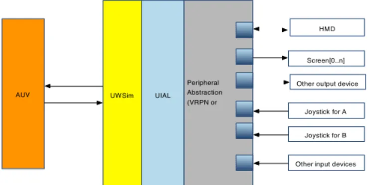
(3) . This article has been accepted for publication in IEEE Computer Graphics and Applications but has not yet been fully edited. Some content may change prior to final publication. JOURNAL OF COMPUTER GRAPHICS AND APPLICATIONS, VOL. X, NO. X, JUNE 2015. requires a deeper understanding on the human cognitive and physical factors that may influence the operator ability to execute the expected operations. From this understanding, special care must be put in designing interfaces to take into account the user dexterity, induced physical fatigue, required mental workload, attentional mechanisms, etc. The objective is that the systems are developed so that the operator (surgeon, pilot, or other) receives the necessary information to perform the task without the need to search for it, and all the controls must be accessible in a simple and effective way. 1.3 Contributions and paper organization Guided by these principles, in this paper we present a solution for the teleoperation problem based on exploring an immersive system. Such system is used to induce a telepresence feeling so that the operator acts as if he/she was aboard of the robot, reducing the mental workload induced by third-person views. The recent introduction on the market of devices like KinectTM and Leap MotionTM , which are able to track and estimate the pose of the human body and hands, seems to create an excellent opportunity to replace the traditional joysticks, keyboards and mice. This motivated the study of their benefits by measuring parameters related to task performance achieved by a group of users and analyzing their subjective evaluation in terms of usability, perceived task load and immersive feeling. The rest of the paper is organized as follows: Section two presents the proposed architecture and implementation details. Section three shows and discusses about the user experience evaluation. Section four presents the conclusions.. 2. D ESIGNING AN IMMERSIVE TELEOPERATION SYSTEM Traditional remote control setups, which typically are composed of multiple displays and controls, frequently require several specialized operators in cooperation. Our proposal aims at simplifying the remote operation control setup, by exploring the principle of telepresence. Our assumption is that if, by the use of some devices, the operator can experiment the sensation of being inside the robot, disposing of a wide field of view, and then the control task becomes as natural as driving a car. This can be achieved by transforming some of the existent explicit controls into implicit ones, e.g. by controlling the orientation of a camera using head rotation instead of using a joystick or other control for that, reducing both the required dexterity and implied cognitive workload. 2.1 Virtual Cockpit: From explicit to implicit controls Teleoperating any kind of vehicle in some remote environment where the operator cannot have a third-. Fig. 2: Software architecture showing the role of the User Interface Abstraction Layer (UIAL).. person view of it, requires the use of an embedded camera that will be the operator’s eyes. To have the ability to perceive the remote environment, the operator has to be able to rotate the camera left, right, up and down, normally using a supporting pan-and-tilt unit (PTU) for that purpose. This means that the operator has to control the two degrees of freedom of the camera in addition to those required to pilot the vehicle. This represents an increased demand in terms of effort and concentration from the operator. The solution we have designed addresses this problem, and consists in creating a virtual cockpit (VC) for the operator. This can be achieved by using a Head-Mounted Display (HMD), whose orientation is used to control the PTU, so the user’s head movements are implicitly transposed into camera movements. This will enable the user to browse the surroundings of the vehicle, enjoying the sensation of being aboard. By superimposing virtual elements over the camera view, it is possible to create the perception of a cockpit with its instruments. The chosen position on the robot to fixate the PTU and its camera defines the location of the virtual cockpit. This location has to be carefully chosen as it has to be adequate for proportionating the best view for the task to be performed, e.g. navigation and maneuvering the AUV, or controlling a robotic arm. Having a set of inputs to control the movements of the AUV and/or its robotic arm, the user can operate them enjoying the sensation of being there. This fulfills our goal of providing the user a perception similar to that of driving a car, piloting a helicopter, etc. 2.2. Architecture. As in many current robotic applications, our developments are based on the use of the wellestablished Robot Operative System (ROS) framework. Nevertheless, we will not go into the details related to the framework choice, as our proposed architecture could be built upon other frameworks, e.g. YAML or GeNoM.. Digital Object Indentifier 10.1109/MCG.2015.118. 0272-1716/$26.00 2015 IEEE.
(4) . This article has been accepted for publication in IEEE Computer Graphics and Applications but has not yet been fully edited. Some content may change prior to final publication. JOURNAL OF COMPUTER GRAPHICS AND APPLICATIONS, VOL. X, NO. X, JUNE 2015. Contrary to airplanes, cars, and other vehicles, there is still no standard interaction devices for UVs. By consequence researchers need to test and evaluate various combinations of input and output devices. Given that each device has its own characteristics, the replacing of these devices would be a very tough task, as not only each requires specific interfacing, but also the mappings between its controls and the device functions have to be adapted one by one. To simplify this task we propose a new architecture, which is represented on figure 2, and has the characteristic of being highly reconfigurable and adaptable to different types of devices and tasks. This is made possible by the inclusion of the UIAL, which has the role of enabling different interaction devices to be used for the same purpose. It shares some ideas with Open Tracker [8] in terms of reconfigurability and with VRPN [9] in terms of device transparency. In fact both can be used to provide a normalized interface for connecting the supported input devices. UIAL layer is then responsible for appropriate mappings between the devices and the UWSim and back. The UIAL provides the following functionalities: • Receives the information from the robot sensors, and robot internal state. • Transforms the data into the best representation for each visualization device. • Maps the outputs of the controlling devices in the appropriate commands for the robot actuators. • Adapts the previous operations depending on the specificities of each task. • Requests the simulator for generating visualizations needed by some o f t h e output devices. The UIAL may reconfigure the use of both the input and output devices according to the mission or the task. It may be responsible for implementing some safety measures to prevent undesirable accidents from user errors. As an example, if the sensors say that the robot is close to the seafloor, any command to take the robot deeper will be ignored. 2.3 A more immersive interface To achieve the aforementioned goal of creating a simpler and more natural user interface for teleoperating robots, in particular UVs, we have designed a system that takes the user aboard of the remote vehicle inside a virtual cockpit. This should overcome the limitations, of having a single camera view whose orientation is manually controlled, that normally result in higher demands in terms of concentration, attention, etc. Instead of this, and taking advantage of the already presented UIAL, we have designed a system based on the use of a HMD, that enables the user to look in any direction. By proportionating a first person wide field of view, it should induce a sense of presence on the operator, enabling him/her to pilot the UV as if being aboard of it.. Being the communications supported by cables, with most of the data flowing from the vehicle to the control station, we can expect that no important delay be introduced in the commands sent to the PTU. Concerning the PTU response, commercial PTUs can have very high performance, exhibiting speeds higher than 100 degrees per second. This is, in fact, below the maximum rota- tional speed of that the human head can attain, which can be as high as 365 ± 96 degrees/s [10]. Nevertheless, these higher rotational speeds are normally attained in response to frightening events, and not in normal conditions of operating or driving a vehicle like a car. In these cases, neck rotations at speeds of tens of degrees/s are used for browsing the view field or visually tracking moving targets. This should enable the user to behave as if he is aboard of the remote robot, and attain a better level of control. For the control of the robot we have tested both a joystick and a Leap MotionTM (LM-device), as the latter seems very promising in terms the variety of natural gestures that can be used as inputs to different navigation controls. A noted limitation was the lack of perception of the relative position of the hand with respect to the LM-device. Another aspect is the need for a reference frame for the operator, so that he can perceive in any instant if he is looking in the forward direction of the robot, up, down or elsewhere. For this reason an Augmented Reality approach was taken by adding two virtual elements on a fixed position with respect to the user: a virtual table and a virtual joystick on it. The table acts as the reference object that enables the user to know to where he is looking at. The virtual joystick shows the control that is being applied through the device in use (the real joystick or the LM-device). To improve the perception of the LM-device location, a small fan was placed close to this device. With this the user can sense the airflow and not only perceive its position, but also the vertical distance between the hand and the device by the airflow intensity. A second approach was to enable the user to see himself in the virtual cockpit and perceive the relative position between his hands and the LM-device device. This was done by using an additional RGB-D sensor, located behind the monitor in an upper position and pointing at the table, to capture a 3D point cloud that represents the user body and introduce it on the virtual environment. In summary the proposed teleoperation setup aims at addressing the problem of simplifying the teleoperation of an underwater robot, by taking the user virtually aboard. This setup has the possibility of integrating different interaction modalities and devices always aiming at reducing the number and complexity of controls required for the operation. This justifies for instance the inclusion of the LM-device as it can detect a large spectrum of hand poses and configurations that can be mapped to robot controls. As will be shown later, this type of device is not as precise as we could expect and introduces other types of problems.. Digital Object Indentifier 10.1109/MCG.2015.118. 0272-1716/$26.00 2015 IEEE.
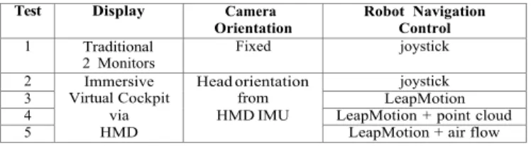
(5) . This article has been accepted for publication in IEEE Computer Graphics and Applications but has not yet been fully edited. Some content may change prior to final publication. JOURNAL OF COMPUTER GRAPHICS AND APPLICATIONS, VOL. X, NO. X, JUNE 2015. 2.4 Implementation The development of the above- p r e s e n t e d ideas was made upon UWSim [11], an open source simulator for underwater robotic missions, which is under development at the Interactive & Robotic Systems Lab, at Universitat Jaume I. This software package is currently used in a few ongoing projects funded by European Commission (e.g. PANDORA) to reproduce real missions from captured logs, for user training, to test algorithms, to monitor the robot or as a 3D simulation tool for benchmarking. The adopted architecture, which is based on ROS, enables the rapid substitution of the simulator by a real robot, or use both in parallel for enhancing the user interface with predictive information. Being one of the purposes of our research to provide insight on which are the best interaction styles and modes for use in the teleoperation of remote robots, and as everyday appear on the market new devices for human interaction, we realized that each of them has to be adapted for each particular use. As an example, two joysticks with different shapes, or a joystick and a yoke-like input, may require different mappings between the device ”axes” and the intended commands. This mapping is not only in terms of establishing pairings, but also on the definition of calibration functions that may vary, between two joysticks, due to shape differences. For instance, using a LM-device the hand movements are tracked and mapped to control the robot using natural gestures: e.g. when the user moves the hand forward/backward/left/right, the robot will move forward/backward/turn left/turn right, and moving the hand up/down will make the robot to go up/down, respectively, etc. Although VRPN libraries enable us to extend the range of devices that can be used, it is the UIAL that is responsible for providing the correct mappings. In addition it introduces the flexibility in performing online activation or deactivation of interaction devices. As an example, it enables the rapid change of the remote PTU control from a joystick to an HMD’s IMU, or the control of the thrust and direction of the robot from a joystick to a LM-device, or other. Apart from performing the adequate mapping between devices and the real robot or the simulator, the UIAL is also responsible for the verification of s a f e t y measures, in order to minimize the possible consequences of human errors. These safety measures are guided by a set of rules which are related to the information provided by some of the onboard sensors, like pressure sensors, proximity sensors, etc.. 3. EVALUATING USER EXPERIENCE. 3.1 Methodology To evaluate the benefits of the proposed changes in the interaction mechanisms for teleoperating remote robots, we simulated a teleoperated underwater vehicle performing a simple obstacle navigation task. We compared our proposed immersive teleoperation approach based on a VC with natural egocentric view, against the traditional teleoperation interfaces that use manual camera control and visualization of mission related information through a set of monitors. Two control devices, joystick and LM-device, were tested in terms of usability. Figure 3 shows a user in different phases of the test and an example of the scene that is visualized. The evaluation consisted in analyzing a set of performance related parameters, which were collected during the experiments, and the answers given to a short questionnaire after each trial. The collected parameters, the questionnaire and their analysis are presented in the remaining of this section. 3.2 Evaluation Procedure For the purpose of evaluating the effect of immersive technologies on the teleoperation of underwater robots, we have designed an evaluation procedure where participants are invited to control a simulated underwater robot with the objective of completing a trajectory. That trajectory includes passing in order through 5 rings that are not collinear and have different orientations, in minimum time and without colliding with the rings or other underwater structures. For each experiment there is a ”warm up” from the starting position until reaching the first ring. The measuring process is started immediately upon passing the first ring. The process is repeated for each of the 5 control setups listed on table 1. For each participant the sequence of the setups is random to avoid effects of learning the trajectory that normally improves the performance for the latters to be executed. In fact, the setups vary in terms of the type of support for visualization of the remote environment, the control of the remote camera orientation, and the robot navigation controls. Test. Display. 1. Traditional 2 Monitors Immersive Virtual Cockpit via HMD. 2 3 4 5. Camera Orientation Fixed. Robot Navigation Control joystick. Head orientation from HMD IMU. joystick LeapMotion LeapMotion + point cloud LeapMotion + air flow. TABLE 1: The five different test setup combinations for the navigation task.. Although the presented interaction mechanism was developed having in mind the control of real robotic plat- forms, for the sake of safety and given that the interest is in evaluating the interface, all the tests described here- after were performed using solely the simulator UWSim.. Digital Object Indentifier 10.1109/MCG.2015.118. The procedure can be summarized as: 1) Participant is instructed about the task objectives and procedures. 2) Execute trial with 1 of the 5 setups.. 0272-1716/$26.00 2015 IEEE.
(6) . This article has been accepted for publication in IEEE Computer Graphics and Applications but has not yet been fully edited. Some content may change prior to final publication. JOURNAL OF COMPUTER GRAPHICS AND APPLICATIONS, VOL. X, NO. X, JUNE 2015. Setup 1. Setup 2. Setup 3. Setup 4. Setup 5. Fig. 3: Experimental setups: (1) Traditional control; (2) VC with joystick and virtual joystick; (3) VC with LM and virtual joystick; (4) VC with LM and point cloud for arms representation; (5) VC with LM and airflow haptic.. 3) 4) 3.3. Fill questionnaire about user experience. Repeat until 5 trials are complete.. Q2: How tiring was the task? (1=Felt tired, 7=Didn’t feel tired) Q3:How precise was the robot control? (1=Not precise, 7=Precise). Measurements and questionnaires. The usability evaluation was performed in two parts: the objection of performance related measures and user subjective evaluation through a questionnaire. Concerning the analysis on performance we measured the following variables directly from the simulator and/or using a third observer to keep records. • Time: navigation time for each of the 4 path segments between rings. • Travelled distance: The length of the executed trajectory for each path segment. • Number of collisions: number of times the robot collided with the elements of the underwater environment, including the rings. • Number of steering compensations: number of issued steering commands for each path segment. For the subjective evaluation a questionnaire was created, which was inspired on the IBM Computer Usability Satisfaction Questionnaire [12], as well as on Slater, Usoh and Steed [13], [14] presence questions. The participant feedback was given by classifying on 7 point Likert scales subjects like: usability, easiness, control precision, fatigue, realness, tele-presence and embodiment feeling. The 8 questions to answer were divided in two groups as follows: Usability & Task load questions Q1: The interface to control the robot was... (1=Easy to use, 7=Hard to use). Q4: Performing the experiment was: (1=Frustrating, 7=Rewarding) Immersion presence questions Q5: I had the impression of being... (1=In the lab, 7=Aboard the vehicle) Q6: How close I felt from the obstacles? (1=Felt close, 7=Didn’t feel close) Q7: How real was the experience? (1=Close to real, 7=Far from real) Q8: The perceived motion sensation was: (1=I was moving, 7=The scenery was moving) 3.4 Participants The experiments were performed both at the University of Coimbra and Universitat Jaume I, with 13 participants from UC and 13 from UJI. The participant group included students and researchers in fields such engineering and computer science, with an overall average age of 30.12 years. All participants reported normal or corrected to normal vision, where 17 had experience with video games. None of them had no prior knowledge of the experience or involved technologies. Participation was voluntary, and research ethical principles were attained. 3.5 Results We can divide the participants results in two groups: the quantitative results taking into account the performance in each setup, and the qualitative evaluation.. Digital Object Indentifier 10.1109/MCG.2015.118. 0272-1716/$26.00 2015 IEEE.
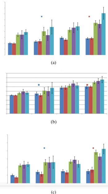
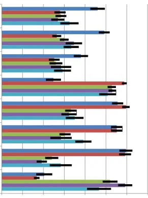
(7) . This article has been accepted for publication in IEEE Computer Graphics and Applications but has not yet been fully edited. Some content may change prior to final publication. JOURNAL OF COMPUTER GRAPHICS AND APPLICATIONS, VOL. X, NO. X, JUNE 2015. Task performance related measures The results are summarized in the following plots for the captured parameters, which are: trajectory time (figure 4a), traveled distance (figure 4b), and number of steering commands or compensations (figure 4c). In these figures wn represents the trajectories between the n and n + 1 rings, for each of the 5 setups.. (F4,95 = 8.57, p < 0.0001∗ on w1 time, F4,95 = 2.94, p = 0.0242∗ on w2 time, F4,95 = 6.44, p = 0.0001∗ on w3 time, F4,95 = 17.79, p < 0.0001∗ on w4 time). Figure 4b presents the mean values for the traveled distances between waypoints, and the significance analysis gives that only y w1 and w4 results are statistically significant. (F4,95 = 2.77, p = 0.0314∗ on w1 dist., F4,95 = 0.87, p = 0.4798 on w2 dist., F4,95 = 0.67, p = 0.6141 on w3 dist., F4,95 = 2.82, p = 0.0290∗ on w4 dist.). Finally, figure 4c presents the mean values of steering commands, and the ANOVA one-way test showed that all the results, except for trajectory segment w2, are statistically significant, as follows: (F4,95 = 15.91, p < 0.0001∗ on w1 Ord., F4,95 = 3.76, p = 0, 0068 on w2 Ord., F4,95 = 7.69, p < 0.0001∗ on w3 Ord., F4,95 = 15.90, p < 0.0001∗ on w4 Ord.).. (a). (b). Fig. 4: Mean values and standard deviation for: (a) trajectory time, (b) trajectory length, (c) number of collisions, and (d) number of steering commands, per trajectory segment and per setup. Figure 4a presents the mean times and variances obtained by the whole set of testers for each path segment (wn), and for each of the setups. The ANOVA (analysis of variance) test was applied and showed that the results are statistically significant (marked with an asterisk).. The plots do not include the number of collisions, as the ANOVA tests show these are not significant from the statistical point of view. (F4,95 = 0.46, p = 0.7609 on w1 Col., F4,95 = 0.99, p = 0.4168 on w2 Col., F4,95 = 0.87, p = 0.4806 on w3 Col., F4,95 = 3.55, p = 0.0095 on w4 Col.). Qualitative evaluation based on user questionnaires In what concerns the questionnaire presented in Section 3.3, the results are presented in figure 5. The ANOVA one-way test results are as follows: (F4,95 = 31, 59, p < 0.0001∗ on question Q1, F4,95 = 37, 97, p < 0.0001∗ on question Q2, F4,95 = 18, 45, p < 0.0001∗ on question Q3, F4,95 = 24, 57, p < 0.0001∗ on question Q4, F4,95 = 32, 19, p < 0.0001∗ on question Q5, F4,95 = 2, 86, p = 0, 0274∗ on question Q6, F4,95 = 14, 06, p < 0.0001∗ on question Q7, F4,95 = 7, 46, p < 0.0001∗ on question Q8). 3.6 Discussion The navigation task performance measures, correspond to the execution of a trajectory, divided in 4 segments (wk, k = 1..4), for each of the 5 setups presented. The task was to drive the robot along pass through each ring that separates a path segment from the next. The user could adapt to the commands during the first part of the trajectory, i.e. till passing the first ring, and then the all the measures were started for w1, then after the second ring for w2, etc. Each of the trajectory segments had its own particularities and implied complexities, as follows: w1 - straight forward, w2 - simple curve, w3 - hard curve, and w4 - variations in altitude ending with a curve. To sum up, these are the devices to use in each setup: Setup 1- Conventional teleoperation setup using 2 monitors and joystick, with no camera control. Setup 2- VC using an HMD for visualization and controlling camera orientation, and joystick.. Digital Object Indentifier 10.1109/MCG.2015.118. 0272-1716/$26.00 2015 IEEE.
(8) . This article has been accepted for publication in IEEE Computer Graphics and Applications but has not yet been fully edited. Some content may change prior to final publication. JOURNAL OF COMPUTER GRAPHICS AND APPLICATIONS, VOL. X, NO. X, JUNE 2015. Fig. 5: Mean scores for the five setups obtained from the users’ answers.. Setup 3- Same as previous, replacing joystick by LMdevice. Setup 4- Same as previous, with representations of the user and LM-device inside the VC. Setup 5- Same as previous, replacing point cloud by air flow-based haptic for LM-device localization. The best mean times, on almost all pathways resulted from using Setup 2, except for w4 where operators presented less time using Setup 1. Using LM-device had generally a negative effect on time performance. Its combination with the airflow solution (Setup 5) showed good results for controlling rotation on a plane, e.g. w3. For more complex cases of changes on orientation and altitudes (ex: w4), Setup 4 presented better results. In these cases, operators did not sense airf l o w changes when moving their hands up and down, but could visualize their hand representation. The lower distances traveled, on w1 and w4 pathways resulted from using both Setups 1 and 2. LM-device based interfaces led to bigger traveled distances, as users also reported that it is less precise. The smallest number of steering order is associated to Setup 2 on w1 and w3 pathways. When dealing with changes in altitude changes (w4), Setup 1 performed better. Setups using LM-device led to higher number of. steering orders. Operators using Setup 2, the immersive virtual cockpit with joystick, presented better quantitative measures for task time performance, traveled distance and number of steering orders. Setup 1, the traditional approach played better on challenges involving orientation and altitude complexities, although the operators did not change the camera point of view leading to higher the dexterity workloads. Analysing answers to questions 1 to 4 we can conclude that: (1) the immersive approaches, with the POV based on head orientation, are both easy to use and intuitive; (2) the users consider important to use a precise device for controlling robot navigation, like the joystick; besides precision, (3) perceiving the range limit of the device and sensing some mechanical feedback from the device is important for the users. This, and the fatigue induced by LM-device use made users tend to the joystick as the preferred control device. From questions 5 to 8 we can conclude that the VC solution is clearly a contribution for the immersion feeling as demonstrated by sensed presence question (Q5). Questions related to tele-embodiment (Q6 and Q8, i.e. virtual contact and self motion) also show a trend to higher immersion rates. Realism question (Q7) presents a moderate trend while the operator perceives the simulator as a game and not as a real environment. The perceived realism of the simulated environment exhibits a correlation with the reported ease of use of the control device. This suggests that the simpler and natural is the interaction, the more immersive becomes the experience.. 4. C ONCLUSION. This paper presented the principle that virtual realityrelated immersive systems can be used to induce the telepresence feeling in remote operation of underwater robots and that this can be used to improve the performance task execution. To this end, a system was developed with the objective of virtually placing the operator aboard of the remote robot and let him/her do the driving tasks from there. The immersive system combines the images, obtained from an orientable camera on the robot, with virtual instruments. This combination is displayed to the user using a HMD, which tracks the user head movements to modify the POV camera. Additionally, the system can be improved adding to the scene the user own representation. The evaluation results showed that the immersive system was t h e o n e preferred by the users. Furthermore, when compared with the traditional interfaces, the use of this immersive system has a positive effect in the teleoperation performance. Concerning the replacement of joystick by a Leap Motion, the results pointed that the lack of touch on the latter has negative effect on the observed user performance and is not appreciated by the users, as they still prefer the former. Another disadvantage reported by. Digital Object Indentifier 10.1109/MCG.2015.118. 0272-1716/$26.00 2015 IEEE.
(9) . This article has been accepted for publication in IEEE Computer Graphics and Applications but has not yet been fully edited. Some content may change prior to final publication. JOURNAL OF COMPUTER GRAPHICS AND APPLICATIONS, VOL. X, NO. X, JUNE 2015. the users for the Leap Motion is the fatigue that results from ”keeping the hand in the air”. Nevertheless, adding both an airflow-based haptic sensation to enable the user to locate the Leap Motion device, or the inclusion of a representation of it the user hand via a point cloud in the virtual environment, showed improvements in the results, in particular for the first one. To sum up, the combination of the immersive virtual cockpit, with implicit control of the remote camera orientation from the user head orientation, and joystick, has shown to produce the best results in terms of performance and is the preferred by the users.. A CKNOWLEDGMENTS This research was partly supported by Spanish Ministry of Research and Innovation DPI2011-27977-C03 (TRITON Project). R EFERENCES [1] L. Almeida, B. Patrão, P. Menezes, and J. Dias, “Be the robot: Human embodiment in tele-operation driving tasks,” in Ro-Man 2014: The 23rd IEEE International Symposium on Robot and Human Interactive Communication, Edinburgh, UK, 2014. [2] B. Patrão and P. Menezes, “A virtual reality system for training operators,” International Journal of Online Engineering, vol. 9, no. 8, pp. 53–55, 2013. [3] MBARI Ridges 2005 Expedition. [Online]. Available: http://www.mbari.org/expeditions/ridges2005/august 15.htm [4] Health and S. E. (HSE), Eds., Reducing Error and Influencing Behaviour (Guidance Booklets). HSE Books, 1999. [5] T. Sheridan, Telerobotics, Automation and Human Supervisory Control. USA: MIT Press, 1992. [6] K. C. C. R. P. J. Dicianno BE, Sibenaller S, “Joystick use for virtual power wheelchair driving in individuals with tremor: pilot study,” Journal of Rehabilitation Research and Development, vol. 46, no. 2, pp. 269–75, 2006. [7] J. Garcı́a, J. Fernández, P. Sanz, and R. Marı́n, “Increasing autonomy within underwater intervention scenarios: The user interface approach,” in 2010 IEEE International Systems Conference, San Diego, CA, USA, 2010, pp. 71–75. [8] Opentracker v2.0 - an open software framework for virtual reality input. [Online]. Available: https://www.ims.tuwien.ac.at/projects/opentracker2 [9] VRPN: Virtual reality peripheral network. [Online]. Available: http://www.cs.unc.edu/Research/vrpn/ [10] U. Röijezon, M. Djupsjöbacka, M. Björklund, C. Häger-Ross, H. Grip, and D. Liebermann, “Kinematics of fast cervical rotations in persons with chronic neck pain: a cross-sectional and reliability study,” BMC musculoskeletal disorders, vol. 11, 2010. [11] M. Prats, J. Pérez, J. Fernández, and P. Sanz, “An open source tool for simulation and supervision of underwater intervention missions,” in 2012 IEEE/RSJ International Conference on Intelligent Robots and Systems, 2012, pp. 2577–2582. [12] J. R. Lewis, “Ibm computer usability satisfaction questionnaires: Psychometric evaluation and instructions for use,” IBM - Human Factors Group, Boca Raton, FL, Tech. Rep., 1993. [13] M. Slater, M. Usoh, and A. Steed, “Depth of presence in virtual environments,” Presence-Teleoperators and Virtual Environments, vol. 3, no. 2, pp. 130–144, 1994. [14] M. Usoh, E. Catena, S. Arman, and M. Slater, “Using presence questionnaires in reality,” Presence: Teleoperators and Virtual Environments, vol. 9, no. 5, pp. 497–503, 2015/04/01 2000.. Digital Object Indentifier 10.1109/MCG.2015.118. Juan C. Garcı́a holds a B.S. in Computer Science and a M.Sc. in “Intelligence Systems” from the Universitat Jaume I, Castellon (Spain). His current research interest is underwater robotics and his actual work is related to the Graphical User Interface and Human-Robot Interaction, focused on underwater robotics. Email: [email protected]. Bruno Patrão received the M.Sc. in Visual Information Technologies from University of Coimbra in 2011. He is currently a Ph.D student at UC- ISR and is interests include Virtual and Augmented Reality Environments, Interactive Systems and Computer Graphics. Email: [email protected]. Luı́s Almeida has a degree in Electrical Engineering from the University of Coimbra. He is currently a Ph.D. student at UC-ISR. His main scientific interests are Computer Vision, Robotics and Computer Graphics. Email: [email protected]. Javier Pé rez is a PhD student at Universitat Jaume I (Spain), and holds a B.S. in Computer Science and a M.Sc in ”Intelligence Systems”. His current research area is underwater robotics and his recent works are focused on benchmarking techniques using a underwater robotic simulator (UWSim) for underwater manipulation. Email: [email protected]. Paulo Menezes is a tenured Assistant Professor at the University of Coimbra, and a senior researcher at the UC-ISR. He develops activities in areas such as Computer Vision, HRI, AR/VR and Human Behaviour Analysis. He participates in several National and European R&D projects in these areas. Email: [email protected]. 0272-1716/$26.00 2015 IEEE.
(10) . This article has been accepted for publication in IEEE Computer Graphics and Applications but has not yet been fully edited. Some content may change prior to final publication. JOURNAL OF COMPUTER GRAPHICS AND APPLICATIONS, VOL. X, NO. X, JUNE 2015. Jorge Dias is an Associate Professor at the University of Coimbra (UC), and holds his research activities at the UC-ISR. His current research areas are Robot Vision, Computer Vision, Human-Robot Interfaces and Social Robots, with activities and contributions in these fields since 1984. He has been the principal researcher in several European research projects. Email: [email protected]. Pedro J. Sanz is Full Professor in the Computer Science and Engineering Department at Universitat Jaume I (Spain), and head of the IRS-Lab. He has been active since 1990 in R&D within several projects on Advanced Robotics and Multimedia Interfaces. He is author or co-author of a broad range of research publications and is an active member of different scientific societies such as IEEERAS, IFAC, EUCog and Eurobotics. Email: [email protected]. Digital Object Indentifier 10.1109/MCG.2015.118. 0272-1716/$26.00 2015 IEEE.
(11)
Figure

+2
Documento similar