A New Design of a Microstrip Antenna With Modified
Ground for DCS and WiMAX Applications
Issam Zahraoui1*, Ahmed Errkik1, Jamal Zbitou1, Elhassane Abdelmounim2, Angel Sanchez Mediavilla3
1LMEET Laboratory FST of Settat Hassan 1st University, Morocco 2ASIT Laboratory FST of Settat Hassan 1st University, Morocco
3DICOM Laboratory, university of Cantabria Santander, Spain
E-mail: [email protected]
Abstract-This paper presents a novel design of a
pentagonal-shaped planar dual-band monopole antenna with a modified ground structure. The validated antenna is compact with a size of 57x50x1,6 mm3. It is printed on an FR-4 substrate
and fed by a 50 Ohm microstrip line. The final circuit operates in the DCS frequency band at 1.8 GHz and the WiMAX at 3.5 GHz. To achieve such antenna, we have used different optimization methods integrated in CST Microwave Studio. The obtained results are compared with another electromagnetic solver Ansoft’s HFSS. After the realization, we have tested and validated this antenna. The measurement results present an agreement with the numerical results.
Index Terms- Pentagonal shape, Modified Ground Structure, DCS band, WiMAX band, CST-MW, Ansoft’s HFSS.
I. INTRODUCTION
During the last few years, there has been a growing interest in the use of light weight and compact size multi-band printed planar antennas for wireless communication systems. Therefore, there is an urgent need to improve antenna performances that can operate with multiband frequencies such as the global system for mobile communication (GSM), digital cellular system (DCS), global position systems (GPS), Wireless local area networks (WLAN) which has made rapid progress and several IEEE standards which are available namely 802.11a/b/g/j, universal mobile telecommunications System (UMTS) and the worldwide interoperability for microwave access (WiMAX) [1-6]. For such applications, microstrip patch antenna is one of the most popular and widely used. The reason behind this
interest is the properties which present such as low-profile, ease of fabrication, light weight, compatibility and low cost. Other advantages include ease of integration with other types of microwave integrated circuits and the ability of being used for both linear and circular polarization. However, microstrip patch antennas have limitations such as low gain, low power handling capability and narrow bandwith [7].
There are many techniques which can be used with a microstrip patch antenna to achieve the multiband behavior. These techniques include higher order resonances, resonant traps, combined resonant structures and parasitic resonators [8]. In addition to these techniques, we can use modified ground structure for miniaturization, improve the bandwidth and increase reflection coefficient for multiband antennas [9-12].
In this paper, we have focused our study on the design of a pentagonal-shaped microstrip antenna with a modified ground plane. The following sections will describe the design procedure, simulation, and fabrication of a new dual band antenna structure which can operate in DCS (1.824-1.875 GHz) and WiMAX (3.416-3.520 GHz).
II. DIFFERENT TECHNIQUES TO OBTAIN MULTIBAND ANTENNAS
In literature many techniques are used to realize multiband antennas. Among these techniques, we use higher order resonances [8]. This is illustrated in Fig.1, which shows the resonant
modes of monopole antenna as their length is increased in λ/4 increments.
Fig.1. Higher order resonances
Monopole antenna is frequently used with a length of λ/4. For this case, the antenna resonates at f0 with electric field at the feed is minimum and the current density is maximum. However, a similar condition exists when the same antenna’s length corresponds to 3λ/4. Hence, the monopole antenna can also resonate at 3f0, other natural resonances will also exist at higher frequencies at 5f0. Another method which is used to obtain the multiband behavior is the use of multiple resonant structures [8] often used for mobile communication systems. Two or more resonant structures can be closely located or even co-located with a single feed point in order to achieve multiband operation. This is illustrated in Fig.2, which shows two closely spaced, adjacently located monopoles with a common feed point. The larger element is operational at the lower frequency f1, while the smaller one is operational at the higher frequency f2.
Fig.2. Combined resonant structures
The use of parasitic resonators to the antenna system [8] can achieve the multiband function. This is illustrated in Fig.3, which shows two
monopoles, one of which is fed, whereas the other is parasitically coupled via the near field of the fed antenna. Here the parasitic antenna is shown with a load, which can be used for tuning. Usually, the load would be reactive so as to maintain high antenna efficiency.
Fig.3. Parasitic resonators
III. ANTENNA DESIGN
The geometry of the proposed antenna is shown in Fig.4. It is printed on a low cost FR-4 substrate with a total area of 57x50 mm2 (Lsub x Wsub), and a dielectric constant εr = 4.4, a thickness h=1.6 mm, a loss tangent tan (δ) = 0.025 and a metallization thickness of t=0.035 mm. This antenna is fed by a microstrip line with 50Ω characteristic impedance. The dimensions of the antenna are optimized and miniaturized by using CST Microwave Studio. To compare the obtained results, we have conducted another study by using Ansoft’s HFSS.
Fig.4. Geometry of the proposed antenna with the modified ground structure
After many series of optimization, the final optimized antenna is validated with the following
parameters: Wf = 3 mm, Lf = 22 mm, P1= 30 mm, P2= 15 mm and L1 =42 mm. The total volume of the proposed antenna is (57x50x1.6) mm3.
The design procedure of this antenna is as follow. Firstly, the rectangular patch antenna as shown in Fig.5, is calculated from the following equations [13-14]:
The width of the rectangular patch is given by: 0 0 1 2 2 1 2 1 2 r r r r c W f f (1)
The expression of the effective length constant is given by:
1 2 1 1 1 12 2 2 r r eff h W
(2) The length extension is given by:
( 0.3) 0.264 0.412 ( 0.258) 0.8 eff eff W h L h W h (3) The length of rectangular patch is given by: 2 2 2 eff r eff c L L L L f (4)
Where: c is the free space velocity of light, εr is the relative permittivity of substrate, L is the length of patch, W is the width of the patch, h is the height of the substrate, εeff is the effective relative permittivity of patch, Leff is the effective
length of the patch and fr is the resonant frequency.
Fig.5. Rectangular microstrip patch antenna (Ant1) The obtained parameters of rectangular microstrip patch antenna are L=20mm, W=26mm which are validated at fr =3.5 GHz.
Secondly, the second band is achieved by turning the rectangular microstrip patch antenna (Fig. 5) and passing to a pentagonal shape by using extrude option integrated in CST-MW (as can be seen in Ant2 in Fig.6). Then, in order to attain 1.874GHz frequency, we need to insert slots in the patch and the ground (as shown in Ant3 and Ant4 in Fig.6). By adjusting the position and dimension of the pentagonal shape, inserting slots and modifying the ground structure, we managed to achieve dual-band frequency response centered at about 1.847/3.475 GHz. Fig.6, shows this procedure.
Fig.7, shows the different reflection coefficients corresponding to each antenna 1 to 4.
Fig.7. Different reflection coefficient obtained of each antenna
The frequency response of the proposed dual band antenna is affected by different parameteres. Fig.8, illustrates the simulated reflection coefficient curves with varied P1, P2 and L1. Fig.8 (a) shows the variation of reflection coefficient with varied P1. As can be seen from Fig.8 (a), the center frequency of the second band decreases with the increase of P1 and the opposite happens to the first band. That’s to say, the center frequency of the first band increases with the decrease of P1. Moreover, the bandwidth of the second band is also influenced by P1, and it increases when P1 decreases. Fig.8 (b) shows the simulated reflection coefficient curves with varied P2. It is clear that when P2 increases, the center frequency of the first band increases whereas the second band knows a slight shift. Variation of the reflection coefficient with different values of L1 is plotted in Fig.8 (c). It can be seen from Fig.8 (c) that L1 influences the first and second band. It is evident that when L1 increases, the center frequency of the first and the second band decreases. Moreover, the bandwith of the first and the second band are also affected by L1. They increase when L1 increases. According to this analysis, the two bands of the proposed dual-band antenna can be tuned independently by changing the values of P1, P2, and L1, respectively.
(a)
(b)
(c)
Fig.8. Simulated reflection coefficient of the proposed dual band antenna with varied (a) P1, (b) P2
and (c) L1 while other parameters fixed
As shown in Fig.9, we have an antenna which is validated at 1.847 GHz for the first resonant frequency and a bandwidth (1.824-1.875 GHz) which validates the antenna in the DCS band. The second resonant mode occurs at the
frequency of 3.475 GHz with a bandwidth (3.416-3.520 GHz), which covers the WiMAX band.
Fig.9. Final reflection coefficient versus frequency In order to compare the results in Fig.10, another electromagnetic solver HFSS is used. From Fig.10, we conclude that there is a close agreement between the simulation results in CST-MW and Ansoft’s HFSS [15].
Fig.10. Comparison of reflection coefficient |S11| between CST-MW and Ansoft’s HFSS
In order to elaborate on the behavior of the proposed dual-band antenna, the surface current distributions at frequencies of 1.847 GHz and 3.475 GHz are plotted in Fig.11. We can clearly notice that the surface current distributions at these two frequencies are not similar. When the first resonant frequency is at 1.847 GHz, most of the surface current is concentrated in the middle of the pentagonal shape and the upper part of the feeding line Fig.11 (a). As indicated in Fig.11 (b), the surface current distribution becomes
more concentrated on the lower part of the pentagonal shape and it is also concentrated along the rectangular-shaped slot in the ground at 3.475 GHz.
Fig.11. Current distributions of the proposed antenna at: (a) 1.847GHz and (b) 3.475 GHz
As shown in Fig.12, we have a stable and bi-directional radiation pattern for the resonant frequency bands.
(a)
(b)
Fig.12. Radiation pattern of the proposed antenna on CST: (a) 1.847 GHz (b) 3.475 GHz
From Fig.13, we notice that the VSWR is less than 2 at the frequency range of (1.820-1.880GHz GHz) and (3.402-3.524 GHz).
Fig.13. VSWR Vs frequency
Fig.14, presents the variation of the gain versus frequency. After the simulation, we have obtained the gain 0.611 dB at 1.847 GHz and 3.560 dB at 3.474 GHz.
Fig.14. Gain Vs frequency
IV. EXPERIMENTAL RESULTS AND DISCUSSION
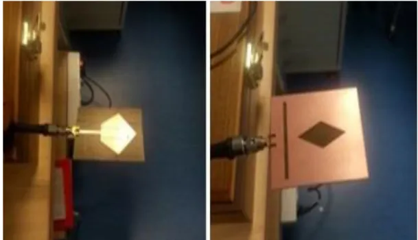
After the design and optimization of the dual-band antenna by using CST-MT, and after comparing the results by using Ansoft’s HFSS, we have conducted the realization to check the performance of the simulation results of the reflection coefficient . The fabricated dual-band antenna is shown in Fig.15.
Fig.15. Photo of the fabricated antenna structure After testing the achieved antenna, we have conducted comparison between simulation and measurement results Fig.16. The measurement is performed with a Vector Network Analyzer (VNA) from Rohde & Schwarz. The calibration Kit used in the measurement setup is 3.5 mm from Agilent Technologies. We notice that there is a close agreement between simulation and measurement results of the reflection coefficient of the optimal proposed antenna. The difference between the measurement and simulation results is due to the lower quality of port SMA used, uncertainty in substrate thickness and dielectric constant.
Fig.16. Comparison of simulated and measured at level of reflection coefficient |S11|.
Table 1. presents a synthesis of the different results obtained by simulation and measurement. Table 1: Comparison between simulation and measurement results of the proposed antenna
Operating frequency Band Resonant frequency (GHz) Return loss (dB) Bandwith (GHz) S im u la te d r e s u lt s b y C S T -MW Firs t re s o n a n t 1.847 -13.484 1.824-1.875 S e c o n d re s o n a n t 3.475 -14.682 3.416-3.520 S im u la te d r e s u lt s by A ns of t’s H FS S Firs t re s o n a n t 1.870 -13.109 1.840-1.900 S e c o n d re s o n a n t 3.610 -11.008 3.580-3.630 Mea s u re d r e s u lt s Firs t re s o n a n t 1.860 -15.929 1.820-1910 S e c o n d re s o n a n t 3.522 -17.645 3.482-3.632
The results presented in Table 1 show that the proposed antenna can be suitable for DCS and WiMAX applications.
V. CONCLUSION
In this study, a novel pentagonal compact antenna is developed and validated with a modified ground plane. This antenna has been designed and optimized by using CST-MW and HFSS electromagnetic solvers. The achieved and tested planar antenna presents a good agreement between simulation and measurement results. These results validate this circuit for DCS (1.824-1.875 GHz) and WiMAX (3.416-3.520MHz) frequency bands with a compact size of 57x50 mm2.
ACKNOWLEDGMENT
We would like to thank Mr. Angel Mediavilla Sanchez Director of DICOM Laboratory in Spain, for allowing us to perform simulations by using electromagnetic solvers and to use many instruments for measurement.
REFERENCES
[1] C. W. Chiu and C. H. Chang, “Multiband folded
loop Antenna for Smart phones”, Progress In
Electromagnetics Research, Vol. 102, pp.
213-226, Sept. 2010.
[2] W. S. Chen and B. Y. Lee, “A Meander PDA
Antenna for GSM/DCS/PCS/UMTS/WLAN
applications”, Progress In Electromagnetics
Research Letters, Vol. 14, pp. 101-109, Jan. 2010.
[3] Y. Q. Zhang, X. Li, L. Yang, and S.-X. Gong,
“Dual-band circularly polarized antenna with low
wide-angle axial-ratio for tri-band GPS
application”, Progress In Electromagnetics
Research C, Vol. 32, pp. 169-179, 2012.
[4] S. Manafi, S. Nikmehr, and M. Bemani, “Planar
Reconfigurable Multifunctional Antenna For WLAN /WIMAX / UWB/ PCS/ DCS/ UMTS Applications”, Progress In Electromagnetics
Research C, Vol. 26, pp. 123-137, Jan. 2012.
[5] H. F. Huang and W. Zhao, “A Small Size
Three-Band Multi-Functional Antenna for
LTE/GSM/UMTS/WIMAX Handsets,” Progress
In Electromagnetics Research, Vol. 49, pp.
105-110, Nov. 2014.
[6] L. H. Wen, Y. Z. Yin, Z. Y. Liu, D. Xi, M. Zhang
and Y. Wang, “Performance Enhancement Of tri-band Monopole Antenna For WLAN/WIMAX Applications”, Progress In Electromagnetics
Research Letters, Vol. 15, pp. 61-68, Jan. 2010.
[7] S. P. Nakar, “Design of a compact microstrip
patch antenna for use in wireless/cellular devices”, M. S thesis, Dept. of Electrical And Computer Engineering, University of Florida, USA, Mar. 2004.
[8] Y. Huang and K. Boyle, Antennas: from theory to
practice, Chichester, UK: John Wiley & Sons Ltd,
Aug. 2008.
[9] Y. J. Sung, M. Kim, and Y. S. Kim, “Harmonics
Reduction with Defected Ground Structure for a Microstrip Patch Antenna”, IEEE Antennas and
Wireless Propagation Letters, Vol. 2, pp. 111-113,
Mar. 2003.
[10] C. S. Kim, J. S. Park, D. Ahn and J. B. Lim, “A
novel 1-D periodic defected ground structure for planar circuits”, IEEE Microwave and Guided
Wave Letters, Vol. 10, pp. 131-133, Apr. 2000.
[11] J. X. Liu, W. Y. Yin, and S. L. He, “A new
defected ground structure and its application for miniaturized switchable antenna”, Progress In
Electromagnetic Research, Vol. 107, pp. 115–128,
Apr. 2010.
[12] H. Elftouh, N. A. Touhami, M. Aghoutane, S. E.
Amrani, A. Tazon and M. Boussouis,
“Miniaturized Microstrip Patch Antenna with
Defected Ground Structure”, Progress In
Electromagnetic Research C, Vol. 55, pp. 25-33,
[13] Constantine A. Balanis, Antenna Theory and
Design, John Wiley & Sons, Inc., Jan. 1997.
[14] W.L. Stutzman, G. A. Thiele, Antenna Theory and
design, John Wiley & Sons, 2nd Ed., New York,
Oct. 1998
[15] A. Vasylchenko, Y. Schols, W. De Raedt, and G.
A. E. Vandenbosch, “Quality assessment of computational techniques and software tools for
planar antenna analysis”, IEEE Antennas