Author’s post-print: Mar Alonso Martínez, Juan José del Coz Díaz, Antonio Navarro Manso and Daniel Castro 1
Fresno. “Bridge-structure interaction analysis of a new bidirectional and continuous launching bridge mechanism” 2
Engineering Structures 59 (2014) 298–307. http://dx.doi.org/10.1016/j.engstruct.2013.10.039 3
Bridge-structure interaction analysis of a new bidirectional and
4
continuous launching bridge mechanism
5
Mar Alonso Martínez
1, Juan José del Coz Díaz
2*Antonio Navarro Manso
3and
6Daniel Castro Fresno
1 71GITECO Research Group, ETSICCP, University of Cantabria, 39005 Santander (Spain)
8
2Department of Construction, EPI Gijón, University of Oviedo, 33204 Gijón (Spain)
9
3Department of Energy, EPI Gijón, University of Oviedo, 33204 Gijón (Spain)
10 11
1 Introduction
12
Incremental launching is an inexpensive and useful technique to erect bridge structures. This 13
method is based on pushing the bridge structure using several devices which provide the friction 14
force needed to move the bridge. This method has been applied since the nineteenth century in 15
Europe and it is currently very widely used around the world [1]-[2]: Bridge over the Caroni 16
River (Venezuela); Bridge over the Danube river (Müller, Austria); Bruggen Viaduct over the
17
Sitter river (Switzerland); Vaux Viaduct between Lausanne and Bern (Switzerland), and so on.
18
Initially, the friction-based launching method was only used for concrete structures, due to the 19
high normal load provided. However, steel structures can currently be launched by friction [3]-20
[4]. Some of the most important bridges in the world were made using this technique, such as the 21
Millau Viaduct in France, which was built from 2001 to 2004, or the “Arroyo Las Piedras
22
viaduct”, the first composite steel-concrete high-speed railway bridge built in Spain [5].
23
Although this technique is very widely used, it has several disadvantages which must be 24
overcome in order to improve constructions methods [6]-[7]. 25
An important problem in ILM is the local stress in the cross section which gives rise to the patch 26
loading phenomenon. This structural local failure is the most important effect in the case of steel 27
bridges and it is an important research line currently [8]-[10]. The normal load on the launching 28
* Corresponding Author: Prof. Juan José del Coz Díaz
Edificio Dep. Viesques 7, despacho 7.1.02 – Gijón – 33204 (SPAIN) Email: [email protected] (+34-985182042)
devices is not distributed and uniform, so the normal reaction exerts a local force in the bridge 29
structure which can cause the collapse of the bridge. Previous authors studied the non-uniform 30
distribution of bearing stress on a launching shoe [11].In that study the authors developed an 31
analytical model which describes the distribution of the support’s reaction. They demonstrated 32
that the normal load applied on the launching shoe is a concentrated load in the center of the 33
launching shoe instead of being a uniform distribution of reaction over the whole load-bearing 34
surface. Other authors studied strategies for analysis of construction stages, showing the internal 35
stress redistribution due to restrained creep [10]. 36
Based on previous works, it is known that the interaction between the bridge and the launching 37
devices is very important. This contact surface is very important in order to ensure the correct 38
launching using the friction force. In this sense, this paper presents a numerical study of the 39
structural interaction between a bridge and a new device to launch structures by friction force 40
[12]. This paper provides a valuable contribution to the civil engineering field focused on a new 41
method for launching bridges by a continuous and bidirectional mechanism. The structural 42
interaction between the bridge and the mechanism which pushes the bridge is studied by 43
numerical methods following the process utilized in other research works in which these 44
methods were used successfully [13]-[14]. 45
The authors of this paper have worked in a new design to launch bridges using friction force. 46
This new design improves the current methods, obtaining a new procedure that is more efficient, 47
economical and safe. The current methods of launching bridges need several hydraulic jacks to 48
place the bridge in its final position [3]-[4],[7]. Vertical and horizontal launching jacks move the 49
bridge using the force of friction as is shown in Fig. 1. The procedure of launching the bridge 50
using this system is as follows: first, the vertical jacks provide the necessary force between the 51
mechanism and the bridge, then horizontal jacks move the bridge structure forward. In order to 52
induce the displacement by friction force, a surface contact is necessary between the bridge and 53
the launching device. Pushing the bridges is a frequently used technique in spite of several 54
problems. This research group has worked on this method for years in order to improve 55
launching safety, as well as to decrease the operation time and to achieve higher average speed in 56
the launching process. 57
Fig. 1. Operating principle of the hydraulic jacks in bridge launching. 59
There are some shortcomings in the current launching method [3],[7],[15]: 60
Auxiliary systems are needed in order to control the launch and make sure it is 61
safe. 62
The average speed of launching is low because the current mechanisms work at 63
very low speed. 64
The method is discontinuous due to the retraction of the launching jacks. For this 65
reason, there is a lot of dead time which are inefficient. 66
The current method is unidirectional because the structure only pushes forward. 67
Backward displacement is obtained using other auxiliary systems. For this reason, 68
the launching procedure is slow and expensive when backward displacement is 69
required. 70
For these reasons, the study of the structural interaction between the bridge and the launching 71
mechanism is a very important research line to avoid problems during the launching procedure 72
[10-11]. It is very useful to analyze the adaptation of the new launching device to the deformed 73
shape of the bridge structure when this is being built. Furthermore, the concentrated load in the 74
steel webs of the bridge during the launching process is an important problem in the current 75
launching methods. The new launching device developed in this innovative paper improves the 76
web’s behavior under patch loading effects because the normal reaction is distributed among 77
several support links. 78
In summary, the statement of the problem is based on the current limitations of bridge launching 79
procedures and the research significance is demonstrated by means of the development of a new 80
mechanism for continuous launching of heavy structures. 81
2 DCACLM for heavy structure displacement
82
In order to improve the launching method, a new device able to provide a continuous and 83
bidirectional displacement has been designed. This system pushes the superstructure using the 84
force of friction. This new device was patented by the authors of this paper in 2011 (WO 85
2013/001114A1) [12]. This patent is referred to in this paper as DCACLM. 86
Two design factors were taken into account: 87
The bidirectional and continuous displacement. 88
The high normal load which has to be supported. 89
The DCACLM device pushes the bridge structure both bidirectionally and continuously. The 90
design of this device is based on an inverted crawler which can move in two directions, forward 91
and backward. Furthermore, the track-crawling have the ability to adjust their components to the 92
terrain in order to increase adherence. Another important requirement of the mechanism is to 93
support high normal loads due to the dead weight during the launching process. The DCACLM 94
device can launch the structure by force of friction from a fixed point on the abutment [16][17]. 95
The device consists of several chains joined together by bolts whose links have a specially 96
designed geometry to support the normal load (see Fig. 2). Furthermore, there are two 97
transmission chains which are used for transmitting mechanical power generated by a couple of 98
engines which activate several gear wheels. These sprockets move the transmission chains. In 99
this way, continuous and bidirectional movement is possible. 100
101
Fig. 2. Mechanism based on terra mechanism vehicles: main elements (above) and overall 103
view with main dimensions (below). 104
105
2.1 The problem of structural interaction in the launching method
106
The new device studied in this paper provides a new construction system to displace heavy 107
structures in a continuous and bidirectional way. This device was designed as a new system to 108
construct bridges. This new system of construction consists of launching bridges with spans 109
greater than 120 m. without auxiliary systems. This system is more efficient than current 110
systems. Higher speed is achieved using the new DCACLM device, as well as greater safety and 111
better load control during the launching, and the environmental effects of civil constructions are 112
reduced due to the decrease in the use of auxiliary systems. Despite the advantages, there are 113
some drawbacks with the use of the new DCACLM system. One of the most important is the 114
contact surface between the bridge structure and the launching mechanism. This contact surface 115
is needed to achieve the friction force which induces the bridge displacement. The DCACLM 116
device is placed under the bridge structure as Fig. 3 shows. 117
118
Fig. 3. Bridge structure over the new launching device. 119
Previous studies related to steel bridge launching led to significant observations that had to be 120
taken into account in the new DCACLM launching device. These considerations are mainly to 121
do with the non-uniform distribution of loads in the launching shoe [11] and other internal 122
effects on the bridge structure [10],[14],[18]. Several experimental tests show two effects which 123
are also disadvantages for the new DCACLM device. First, the load distribution and the girder 124
curvature were tested and it was found that the geometrical imperfections affect the reaction 125
distribution. Second, horizontal friction tests show that the coefficient of friction varies 126
depending on the stress distribution on the launching jacks. The different values of the vertical 127
load affect the horizontal launching force. In this sense, the new DCACLM device suffers these 128
problems during the launching process due to the non-uniform distribution of the normal load 129
over the support links. 130
The load distribution and the structural interaction between the structure and the DCACLM 131
device is studied in this research paper using numerical modeling. 132
133
2.2 Description of the strategy
134
The finite element method is a powerful tool to study structural analysis. The sub-structuring 135
technique is an advanced tool that is used to study the structural interaction between the bridge 136
and the DCACLM device. The sub-structuring technique is also very useful for many kinds of 137
structural analysis [19]-[20]. The main objective of this technique is to reduce two complex, non-138
linear problems to an efficient numerical model. In this way, it is possible to study two non linear 139
numerical models and their interaction while reducing computational time and resources. The 140
non-linear numerical model of the bridge structure has more than 500,000 Degrees of Freedom 141
(DOF) and the non-linear model of the launching mechanism has more than 400,000 DOF. 142
However, the combination of them using the sub-structuring technique is 303,541 which is less 143
than half of the other two problems separately. 144
Sub-structuring is a technique that combines a group of finite elements into one element [21]. 145
This element is represented by a matrix. In this way, it is possible to reduce a non linear 146
numerical model to a simplified one to obtain a linear response. 147
In this case, the non linear numerical model of the bridge structure is reduced to one finite 148
element which is called “superelement”. The superelement has several nodes, called “master 149
nodes”, whose degrees of freedom (DOF) are set depending on the boundary conditions. The 150
“master nodes” are needed to connect the superelement to the rest of the numerical model, in this 151
case the new launching device. The global model of the structural interaction problem consists of 152
the superelement, the numerical model of the launching device and the connection between 153
them. 154
Several commercial programs can solve the sub-structuring problem, such as SAP, ABACUS or 155
ANSYS. In this case, ANSYS was used to solve the structural interaction using a proprietary 156
code written in Advanced Parametric Design Language (APDL) [22-23]. 157
3 Methodology of the numerical modeling using sub-structuring technique
158
3.1 Mathematical model
159
The methodology applied in this paper is based on the substructuring technique which reduces a 160
complex non linear model to a single superelement, which is the bridge structure in this case. 161
The mathematical model of the superelement used, MATRIX 50 [22-23], is a matrix format of 162
an arbitrary structure which does not have a fixed geometrical identity. The first step in the 163
analysis introduces a superelement as one of its element types, this process is named “use pass”. 164
In the second step, named “generation pass”, the master degrees of freedom are specified; in this 165
step, the element load vector is generated along with the element at each load step. Load vectors 166
may be proportionately scaled in the use pass. It is important to consider that the load value is a 167
scale factor. The load vector number is determined from the load step number associated with the 168
superelement generation. If a superelement load vector has a zero scale factor (or is not scaled at 169
all), this load vector is not included in the analysis. Any number of load vector-scale factor 170
combinations may be used in the use pass. A specific flag has been used to indicate that the 171
superelement was generated with constraints, specifically, support at the prefabrication area of 172
the bridge. 173
Within the superelement technique, the following assumptions and restrictions are taken into 174
account: 175
In this case, any degree of freedom may be used. 176
The finite elements inside the superelement have constant stiffness, damping and mass 177
effects without changes in the material properties throughout the analysis. 178
The bases of the superlement are linked with the following static equation [21]: 179
[ ]K u F (1)
Where: 180
{F} includes nodal, pressure and temperature effects. 181
The equations may be partitioned into two groups, the master (retained) DOFs, here denoted by 182
the subscript “m”, and the slave (removed) DOFs, here denoted by the subscript “s”. 183
mm ms m m sm ss s sK
K
u
F
K
K
u
F
(2)Expanding the above system equations: 184
mm m ms s mK
u
K
u
F
(3)
sm m ss s sK
u
K
u
F
The master DOFs should include all DOFs of all nodes on surfaces that connect to other parts of 185
the structure. If accelerations are to be used in the use pass or if the use pass will be a transient 186
analysis, master DOFs throughout the rest of the structure should also be used to characterize the 187
distributed mass, solving the following equation [24]: 188
1
1
s ss s ss sm m
u
K
F
K
K
u
(4) Substituting {us}into equations (3):189
1 1 mm ms ss sm m m ms ss sK
K
K
K
u
F
K
K
F
(5)In the preceding development, the load vector for the superelement has been treated as a total 190
load vector. The same derivation may be applied to any number of independent load vectors, 191
which in turn may be individually scaled in the superelement use pass. For example, the analyst 192
may wish to apply thermal, pressure, gravity, and other loading conditions in varying 193
proportions. Expanding the right-hand sides of equations (3) and (4) gives, respectively [25]: 194
1 N m mi iF
F
(6)
1 N s si iF
F
(7) 1953.2 General strategy to study the structural interaction by sub-structuring
196
technique
197
The global numerical model consists of the superelement and the non-linear numerical model of 198
the launching device. The numerical model of the bridge structure is reduced to an element, the 199
superelement, whose nodes are called “master nodes”. The degrees of freedom (DOF) of these 200
master nodes are set to provide the normal load from the bridge structure to the new DCACLM 201
device in the vertical direction. In order to obtain the global numerical model the following 202
procedure based on the sub-structuring technique was developed: 203
1. Develop the simplified numerical model of the bridge structure. The numerical model of 204
the bridge is reduced to a MATRIX50 element [22-23]. This has several nodes which 205
provide the load transmission from the bridge to the new launching device. The boundary 206
conditions of this element depend on the global boundary conditions. 207
2. Verification of the bridge structure superelement in a simple numerical problem. In this 208
stage, the superelement is tested in known conditions in order to demonstrate the linear 209
behavior of the simplified numerical model. In this case, the superelement is supported 210
by two vertical bearings. The reaction in those supports must be the weight of the bridge 211
structure. 212
3. Develop the non linear numerical model of the new DCACLM device. The numerical 213
model of the new device is a simplified model which supports the bridge structure. In this 214
numerical model several kinds of finite elements, which include nonlinear capabilities 215
[25], are used. In this way, it is possible to reproduce the contacts between elements and 216
the transmission of the normal load through the resistant parts of the mechanism. 217
4. Connection of the previous numerical model. The superelement and the non-linear 218
numerical model of the DCACLM device are connected in two different ways: linear 219
simulation and non-linear simulation. Coupled nodes between the superelement and the 220
mechanism were used in the linear model: master nodes from the superelement and nodes 221
of the support sheet from the DCACLM. The non-linear contact was simulated using 222
non-linear contact elements. Both FEM models have been compared in order to find the 223
best way to simulate the structural behavior of the interaction between the bridge and the 224
mechanical device. 225
226
3.3 Numerical model used
227
The numerical model used to solve the structural interaction between the bridge structure and the 228
new DCACLM device consists of three parts: 229
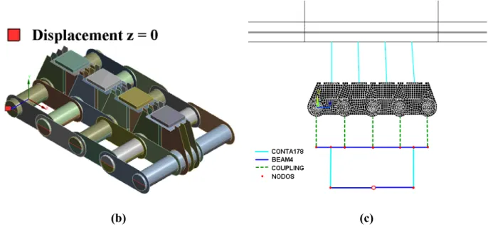
- Superelement of the bridge structure, see Fig. 4(a) 230
- Non linear model of the new DCACLM device, see Fig. 4(b) 231
- Connection between the superlement and the nonlinear model of the DCACLM, and total 232
reaction of the global system, see Fig. 4(c) 233
(b) (c)
Fig. 4. Numerical models used: (a) superelement of the bridge structure; (b) simplified 234
model of the launching device; (c) connections and total reaction supports. 235
The bridge structure is reduced to one element which has several “master nodes”. All the master 236
nodes allow the displacement of the structure in the vertical direction and are restricted in other 237
directions. The boundary conditions of the superelement depend on the sequence of launching: at 238
the beginning of the launching, one support is needed but, when the structure is near to the first 239
pile, the support can be eliminated and the bridge is only supported by the new DCACLM 240
device. The bridge provides the vertical load on sixteen support links of the DCACLM device 241
during the different phases of the launching procedure. This load passes through the contact 242
element, CONTA178 [22-23], and is applied on the center of the sheet of the support link as is 243
shown in Fig. 4(c). The main properties of this nonlinear contact element are shown in Table 1. 244
Table 1. Properties of the non-linear contact element. 245
Parameter Value
Unidirectional gap, vertical direction Pure penalty contact algorithm
Weak spring not used
Standard behavior of contact surface, friction coefficient 0.3
FKN: Normal Stiffness 1.284·107
GAP: Initial gap size 0
START: Initial contact status Closed (1) FKS: Sticking stiffness in tangential direction for closed contact FKN
The reaction is distributed on the main resistant elements of the DCACLM device. There are two 246
main boundary conditions of the global numerical model: on the one hand, the support of the 247
bridge structure during the launching process if necessary; on the other hand, the support of the 248
bolt ends which can restrict movement in the Z direction. Finally, the global system is supported 249
on a group of finite elements that make it possible to obtain the total reaction of the global 250
system. These additional finite element groups in the DCACLM device will be referred to as 251
“system of load compensation” in this paper. 252
The system of load compensation is included in the global numerical model in order to obtain the 253
total reaction. If this value is known, it will be possible to detect large differences in the load 254
distribution. Furthermore, it will be possible to apply vertical loads from the new launching 255
device to the bridge structure in order to adjust the shape. The numerical model of the system of 256
load compensation is shown in Fig. 4(c). It consists of uniaxial finite elements which are known 257
as BEAM4, two contact elements designed as CONTA178, which only transmit the vertical load, 258
as well as a coupling configuration which associates the vertical displacement of the nodes from 259
the bolts to the displacement of the nodes of the BEAM elements [22-23]. 260
4 Cases studies
261
In bridge erections, specifically in large bridge constructions, the construction stages are usually 262
as important as the service life. This is due to the stress distribution within the bridge structure 263
and also other aspects such as the joints among the structure segments or the launching forces of 264
the launching devices on the structure and so on. These problems in construction methods have 265
been studied for years by other authors using non-linear numerical methods [11]-[10]. In this 266
paper the most critical situation from the launching device point of view is near the first pile 267
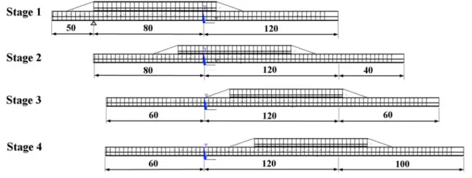
where the bridge structure has a very large deflection. In this paper, four stages around the first 268
pile were studied in order to obtain the reaction force of the bridge structure. 269
270
Fig. 5. Stage of launching process studied. 271
The highest normal reaction on the new DCACLM device, which is placed in the abutment, was 272
obtained in stage 1 when the bridge structure was close to the first pile. In this situation the 273
reaction force on the launching device reaches its highest value. In this stage, two different 274
aspects were studied by numerical simulation using the sub-structuring technique: first, the best 275
arrangement for the new DCACLM launching device was studied in order to choose the best 276
one; and second, the distribution of the load on the new DCACLM device was assessed for the 277
previously chosen arrangement. 278
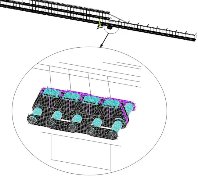
A detail of the numerical model used in all case studies is shown in Fig. 6. 279
280
Fig. 6. Global numerical model used. 281
4.1 Linear and non-linear analyses
283
The contact between the bridge structure and the DCACLM has been studied in two different 284
cases. On the one hand, a bonded linear contact was simulated using coupled nodes in the 285
vertical, Y- direction. On the other hand, a nonlinear frictional contact was modeled using non-286
linear finite elements named CONTA178 [22-23]. The main properties of this element are shown 287
in Table 1. 288
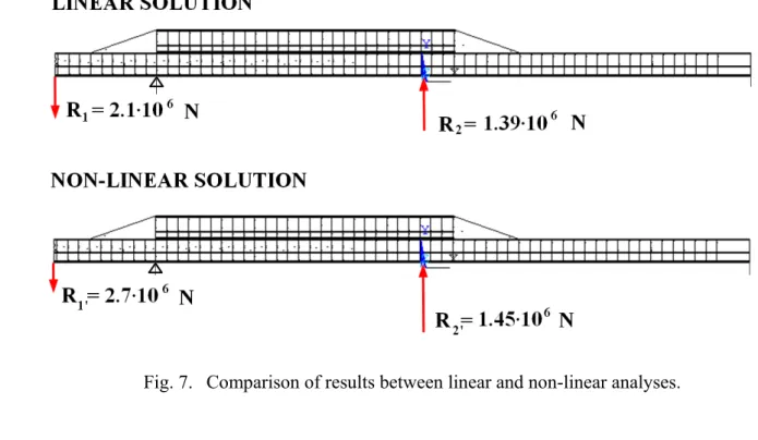
In both cases the total reaction obtained is the same, 1.18·107 N, which also takes into account
289
the DCACLM dead load. However, the structural response is completely different. The results 290
shown in Fig. 7. indicate stiffer behavior for the linear contact than for the non-linear contact. 291
The force reaction in the prefabrication area for the linear numerical model is lower than in the 292
case of the non-linear numerical model. This is due to the stiffness between the superelement and 293
the DCACLM, where the linear coupling makes the joint stiffer than non-linear contact, which is 294
not the real structural behavior. The real behavior is as a vertical support with a specific value of 295
the coefficient of friction. The non-linear contact reproduces the real support more faithfully than 296
the linear model. In this sense, it has been proved that the non-linear analysis simulates the real 297
behavior more accurately than linear analysis. 298
299
Fig. 7. Comparison of results between linear and non-linear analyses. 300
301
4.2 The best arrangement
302
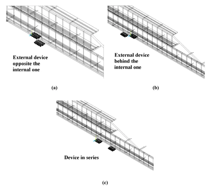
Three different configurations were studied using the sub-structuring method: 303
- Parallel arrangement of the new DCACLM devices with two combinations: a) the external 304
device opposite the internal one, see Fig. 8(a); b) the external device behind the internal 305
one, Fig. 8(b). 306
- DCACLM launching devices in series under the webs of the bridge structure, see Fig. 8(c). 307
(a) (b)
(c)
Fig. 8. Arrangements of the new DCACLM device studied. 308
These three different arrangements were studied in the first stage when 120 m. of bridge are 309
launched and the reaction force in the abutment is at its highest value. In this sense, the results 310
obtained in the arrangements were compared. The best arrangement will be that whose maximum 311
reaction force has the lowest value. 312
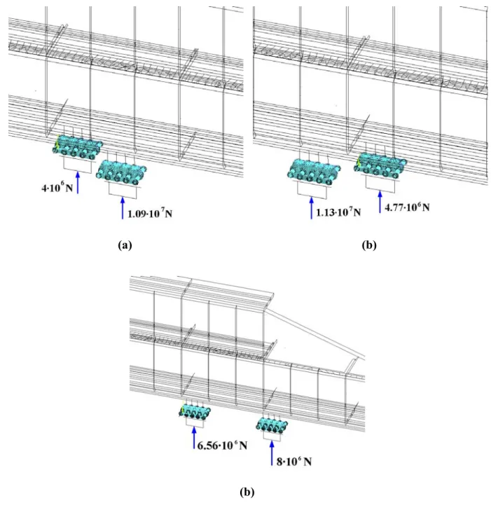
Taking into account the results obtained, the best arrangement of the new launching devices is in 313
series, see Fig. 8(c). If there are two launching devices in series under the webs of the bridge the 314
reaction value is lower than in the other cases studied. The results of the total reaction in the new 315
DCACLM device obtained by numerical methods using the sub-structuring technique are shown 316
in Fig. 8. 317
(a) (b)
(b)
Fig. 9. Total reaction of the DCACLM launching device for the three arrangements. 318
319
4.3 The non uniform distribution of the load
320
When the best arrangement was selected, the distribution of the normal load over the launching 321
device was studied. In all cases, four support links were considered to be the bearings of the 322
structure. 323
The superelement transmits the normal load to the launching device through contact elements, 324
named CONTA178 [22]-[23]. Each master node is joined to the center of the support plate in the 325
support link. The vertical load is applied at this point. It was proved that the total normal load is 326
non-uniformly distributed over the four supports. 327
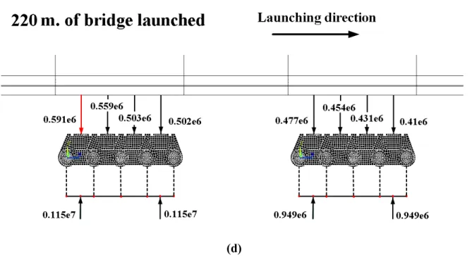
The results obtained for the most critical launching phase are shown in Fig. 10. 328
(b)
(d)
Fig. 10. Non-uniform distribution of the normal load over the DCACLM device for different 329
lengths of bridge launched: (a) 120 m.; (b) 160 m.; (c) 180 m.; (d) 220 m. 330
5 Conclusions
331
A numerical study of the structural interaction between the bridge structure and a new launching 332
device is presented in this paper. This study was carried out using the sub-structuring technique 333
with which two complex numerical models are reduced to a simplified numerical one. The 334
numerical model used takes into account several phases of launching in the construction process, 335
as well as three different positions of the new launching device. 336
The results obtained for each case studied are shown in Table 2. 337
Table 2. Maximum values of the reaction force. 338 PARALLEL DISPOSITION SERIAL DISPOSITION External device opposite internal one External device behind internal one Maximum Force reaction
Maximum force reaction in
each device DCACLM [N] 10.9·106 11.3·106 8·106
The proposed numerical model by sub-structuring and the constraint equations were developed 339
using finite element software, ANSYS Academic Research APDL. The main conclusions 340
obtained in this work are as follows: 341
- A very complicated problem which consists of two non linear numerical models can be 342
simplified to a global numerical model using the sub-structuring technique. This 343
technique enables the reduction of computational power and time. 344
- Three arrangements of the DCACLM launching devices under the bridge structure were 345
studied. The comparison shows that the series arrangement is the best for the DCACLM 346
launching devices. In order to reduce the maximum stress in resistant elements, the 347
DCACLM launching devices should be in series under the webs of the bridges. 348
- The normal load on the launching device is distributed on four support links. The 349
numerical model developed in this paper showed the non uniform distribution of the 350
normal load among the supports. This fact is due to the low local stiffness of the bridge 351
structure. The distribution of the normal load on the support links of the DCACLM 352
launching devices was found in this finite element analysis only for the series 353
arrangement which was chosen as the best arrangement. The same procedure was used to 354
obtain the distribution of the vertical force in four different phases of the launching 355
process. In this way, an approach to the evolution of the normal load distribution was 356
obtained, together with the necessary reaction to compensate the bridge structure 357
deformation. 358
6 Acknowledgements
359
The authors express deep gratitude to the GICONSIME and GITECO Research Groups at 360
Oviedo University and Cantabria University, respectively, for their useful assistance and the 361
anonymous comments and suggestions of the reviewers. This work was partially financed with 362
FEDER funds by the Spanish Ministry of Science and Innovation through the Research Project 363
BIA2012-31609 and the Gijon City Council through the SV-13-GIJON-1.7 project. We would 364
also like to thank Swanson Analysis Inc. for the use of the ANSYS University research program 365
and Workbench simulation environment. Finally, we would like to acknowledge the help of the 366
Spanish Ministry of Economics and Competitiveness through the Research Project ALCANZA, 367
IPT-380000-2010-012 INNPACTO program. 368
References
[1] Leonhardt F, Bauer W. The bridge across the Caroni River from Puerto Ordaz to San 370
Felix in Venezuela. Trends 1964;31:27-29. 371
[2] Bernabeu Larena J. Evolución tipológica y estética de los puentes mixtos en Europa. 372
Doctoral Thesis. Madrid Polytechnic University; Spain. 2004. 373
[3] Rosignoli M. Bridge Launching. Italy. Thomas Telford. 2002. 374
[4] Rosignoli M. Bridge erection machines. USA. HNTB Corp. 2012 375
[5] Millanes Mato F, Pascual Santos J, Ortega Cornejo M. “Arroyo las Piedras” viaduct: the 376
first composite steel-concrete high speed railway bridge in Spain. Hormigón y Acero 377
2007; 243: 5-38. 378
[6] VSL International LTD. The incremental launching method in prestressed concrete 379
bridge construction. Schwarzenburg. Gerber AG. 1977. 380
[7] Manterola Armisén J, Siegrist Fernández C, Gil Ginés MA. Bridges. UP Madrid. 381
ETSICCP 2000. 382
[8] Djelosevic M., Gajic V., Petrovic D., Bizic M. Identification of local stress parameters 383
influencing the optimum design of box girders. Engineering Structures 2012, 40: 299-384
316. 385
[9] Hassanein M.F., Kharoob O.F. Behavior of bridge girders with corrugated webs: (II) 386
Shear strength and design. Engineering Structures, In Press, Corrected Proof, Available 387
online 17 June 2013.
388
[10] Maiorana E, Pellegrino C, Modena C. Linear buckling analysis of unstiffened plates 389
subjected to both patch load and bending moment. Engineering Structures 2008; 30: 390
3731-3738. 391
[11] Granath P. Distribution of support reaction against a steel girder on a launching shoe. 392
Journal of Constructional Steel Research 1998: 47 (3):245-270. 393
[12] International Patent WO2013/001114 A1. Device for continuous movement of 394
structures. 2013 395
[13] Li ZX, Chan THT, Yo Y, Sun ZH. Concurrent multi-scale modeling of civil 396
infrastructures for analyses on structural deterioration. Finite Elements in Analysis and 397
Design 2009; 45:782-794. 398
[14] Somja H, Ville de Goyet V. A new strategy for analysis of erection stages including 399
an efficient method for creep analysis. Engineering Structures 2000; 30:2871-2883. 400
[15] Cruz P, Mari A, Roca P. Non linear time-dependent analysis of segmentally 401
constructed structures. ASCE Journal of Structural Engineering 1998; 124:278-287. 402
[16] Popp K, Schiehlen W. Ground vehicle dynamics. Germany. Springer 2010. 403
[17] Muro T, O'Brien J. Terramechanics: Land locomotion mechanics. Taylor and Francis 404
2004. 405
[18] Mari A. Numerical simulation of the segmental construction of three dimensional 406
concrete frames. Engineering Structures 2000; 22:585-596. 407
[19] del Coz Diaz JJ, Garcia Nieto PJ, Fernández Rico M, Suárez Sierra JL. Non-linear 408
analysis of the tubular ‘heart’ joint by FEM and experimental validation. Journal of 409
Constructional Steel Research 2007; 63(8): 1077-1090. 410
[20] Betegón Biempica C, del Coz Díaz JJ, García Nieto PJ, Peñuelas Sánchez I. 411
Nonlinear analysis of residual stresses in a rail manufacturing process by FEM. Applied 412
Mathematical Modelling 2009; 33(1):34-53. 413
[21] Bathe KJ. Finite element procedures. New Jersey: Prentice-Hall 1998. 414
[22] Moaveni S. Finite element analysis: theory and applications with ANSYS. New 415
York: Prentice-Hall 2007. 416
[23] Madenci E, Guven I. The finite element method and applications in engineering 417
using ANSYS. New York. Springer 2007. 418
[24] Reddy JN. An introduction to nonlinear finite element analysis. Oxford University 419
Press, New York 2004. 420
[25] del Coz Díaz JJ, García Nieto PJ, Betegón Biempica C, Fernández Rougeot G. 421
Nonlinear analysis of unbolted base plates by the FEM and experimental validation. 422
Thin-Walled Structures 2006; 44(5): 529-541. 423
[26] del Coz Díaz JJ, García Nieto PJ, Vilán Vilán JA, Suárez Sierra JL. Non-linear 424
buckling analysis of a self-weighted metallic roof by FEM. Mathematical and Computer 425
Modelling 2010; 51(3-4): 216-228. 426