Low THDi Controller for Current Sensorless Single Phase Rectifiers
using a Two-Sample Phase Locked Loop
Abstract: Two-sample phase locked loop (2S PLL) with harmonic filtering capacity is used in a non-linear control
(NLC) to cancel the current estimation errors in a current sensorless Boost power factor corrector (PFC) to obtain a sinusoidal current independent on the grid disturbances and prevent their propagation. The resulting line current using the proposed PLL 2S against a zero-crossing detector (ZCD) is compared in simulation and experimentally.
1
Introduction
The equivalent behavior of a PFC, within the frequency range of interest, is a lossless resistance whose value will depend on the power supplied to the DC load. Therefore, when the grid presents harmonic distortion, the current spectrum of the power converter will contain, at least, those same frequencies. At higher frequencies than the current control bandwidth, typically around half of the switching frequency, current harmonics may come up due to the non-linearity of the power converter. As a consequence, and in weak grids particularly, the overall harmonic distortion rate of the converter current at the point of common coupling (PCC) may exceed the total voltage harmonic distortion limited
(
THD
i
THD
v)
by the regulations [1].In this sense, when the current sensor is eliminated, the current controller requires the actual input current to be estimated and the harmonic voltage distortion makes it more difficult to rebuild this current without significant errors or to pre calculate the adequate duty cycle sequence for the utility period complying the standards, e.g. IEC 61000-3-2:2005 [2]. In order to improve the current distortion a modification of the digital NLC of a Boost PFC is presented in [3], where the input current tends to be pure sinusoidal regardless of the input voltage distortion by determining the grid frequency with a high frequency counter, which starts with a zero-crossing detector (ZCD) of the line voltage, vg, and generating a reference sine function with one CORDIC block. However, this technique is highly sensitive to disturbances of the grid voltage. Besides, even though the ZCD is a simple strategy, the use of a CORDIC block increases the hardware resources required and the number of clock cycles, which depends on the precision specification for this block. Hence, in this paper it is proposed to replace the ZCD and the CORDIC block by a 2S PLL to obtain the target low THDi operation.
2
NLC applied in a current sensorless Boost PFC
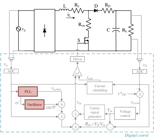
RL D S ADC ADC Voltage control X -v0 v*DC ireb vg C iL Driver Σ -Σ PLL vg L Digital cotrol Current rebuilding sin'θ' vg,max Σ - Carrier signal generator Vm verror vm X Rfic=V0/Vm ÷ Ron RD RL Oscillator ω'Fig. 1: Diagram of the proposed digital control.
As shown in Fig. 1, the digital PFC controller estimates the input current, ireb, instead of measuring it, avoiding the
inconveniences associated with the current sensing in this type of applications [4]. The value of this current is calculated digitally from the values of the input voltage, vg, and output, vo of the Boost converter and is compared with
the carrier signal to determine the switch state (ON and OFF). The equations that define the reconstructed stream are described in [4] as: ON-state: ( ) ( 1) g reb reb v i k i k T L = − + (1) OFF-state: 0 ( ) ( 1) g reb reb v v i k i k T L − = − + (2)
where L is the value of the inductance used in the Boost converter, Ts the sampling frequency and Tcorresponds to
This type of controllers is based on the comparison of a carrier signal, vm, with the input current, which in this case
is ireb. The value of the carrier can be expressed as
( )
1
m m st
v T
V
T
=
−
(3)3
Two-Samples PLL
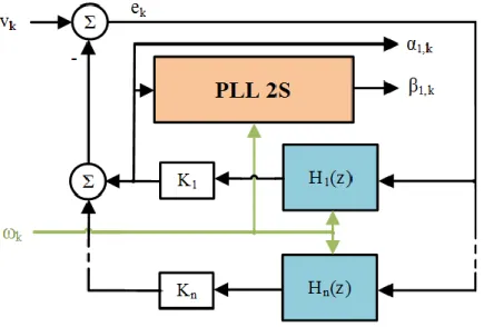
The PLL 2S proposed in [5] is employed in this work with a new harmonic filtering structure embedded in the PLL, as shown in Fig. 2, to make it less sensitive to the grid voltage disturbance and provide a better carrier signal to comply with the current harmonic limits. This structure achieves a good synchronization, with an accurate response to perturbations of the frequency of the grid even when the grid voltage presents harmonic distortion. In the final version, more details of this new structure will be presented.
Fig. 2: Diagram of the harmonic filtering structure
4
Simulation results
The 2S PLL with the harmonic filtering structure and the ZCD integrated in a single-phase Boost PFC model with digital control are compared by simulation.
The response of the PLL 2S and the ZCD to a frequency ramp of +2 Hz under distortion condition (3% and 2% of the 5th and 7th harmonic, respectively) is shown in Fig. 3. The ZCD exhibits worse response under the transient and in the
stationary state where the accumulation of the error that occurs is due to the phase shifts of the harmonic distortion. The 2S PLL achieves lower values of phase error overshoot (1%). This figure includes a phase error limit equal to
0.57ᵒ that corresponds to the precision required in phasor measurements units (PMUs) to obtain a total vector error (TVE) less than 1 % [6].
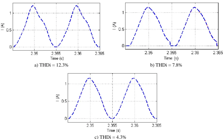
In Fig. 4 the waveforms of the rebuilding current and the current measured in the Boost at steady state at 50 Hz compared to a conventional NLC are shown including the THDi values measured in these signals where the proposal obtains the values lower (4.3%). In the final manuscript, more results will be included.
Fig. 3: Phase error due to a frequency ramp of 0.4 Hz/s during 0.5 s under harmonic distortion (3% and 2% of the 5th and 7th
harmonic, respectively).
a) THDi = 12.3% b) THDi = 7.8%
c) THDi = 4.3%
Fig. 4: Current simulated in the Boost PFC in stationary state at 50 Hz a)conventional control without syncronization, b)
5
Comparison of computational burdens
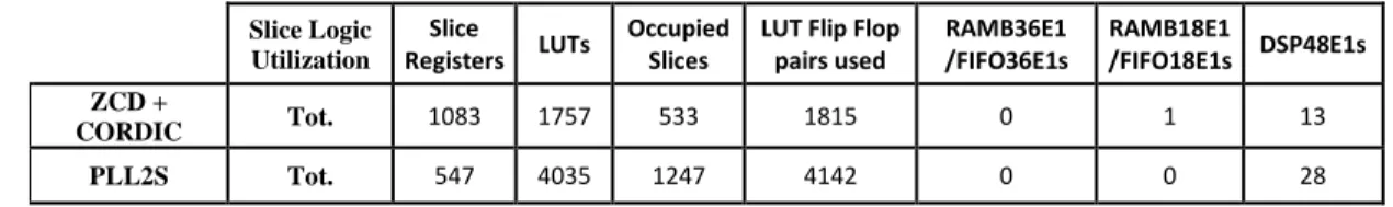
ZCD and 2S PLL have been implemented in a FPGA to study their behavior and computational burden. In Table I, a summary of the resources used in the FPGA is presented for the different strategies analyzed where the ZCD and the CORDIC block require, in general, less FPGA resources than the PLL 2S with the new structure. In the final version, more detailed information will be given.
Table 1: Summary of the FPGA resources used by ZCD and PLL 2S methods.
Slice Logic Utilization Slice Registers LUTs Occupied Slices
LUT Flip Flop pairs used RAMB36E1 /FIFO36E1s RAMB18E1 /FIFO18E1s DSP48E1s ZCD + CORDIC Tot. 1083 1757 533 1815 0 1 13 PLL2S Tot. 547 4035 1247 4142 0 0 28
5
Conclusion
The 2S PLL with a new harmonic filter structure is proposed to work in a NLC control in a current sensorless Boost PFC to obtain a current close to sinusoidal in the converter, independent of the grid disturbances. With this proposal, the control presents a better dynamic response to harmonic distortion and improve the accuracy of the synchronization strategy.
References
[1] V. M. López-Martín, F. J. Azcondo, and A. Pigazo, “Power Quality Enhancement in Residential Smart Grids Through Power Factor Correction Stages,” IEEE Trans. Ind. Electron., vol. 65, no. 11, pp. 8553–8564, Nov. 2018. [2] I. E. Commission, Electromagnetic Compatibility EMC—Part 3-2: Limits for Harmonic Current Emissions
(Equipment Input Current⩽ 16 A per phase), vol. 2. 2005.
[3] V. M. López, “Corrección de Factor de Potencia basada en la estimación digital de la corriente de línea. Aplicación en el Convertidor Boost en modo de conducción continua,” Universidad de Cantabria, 2013.
[4] V. M. Lopez, F. J. Azcondo, A. de Castro, and R. Zane, “Universal digital controller for boost CCM power factor correction stages based on current rebuilding concept,” Power Electron. IEEE Trans. On, vol. 29, no. 7, pp. 3818– 3829, 2014.
[5] P. Lamo, A. Pigazo, G. A. Ruiz, F. J. Azcondo, and F. López, “An Optimized Implementation of a Two-Sample Phase Locked Loop with Frequency Feedback for Single-Phase Sensorless Bridgeless PFC,” in 2018 IEEE 19th Workshop
on Control and Modeling for Power Electronics (COMPEL), 2018, pp. 1–6.
[6] IEEE Standard for Synchrophasor Measurements for Power Systems, IEEE Std. C37.118.1-2011 (Revision of