PRUEBA DE HABILIDADES
CARLOS ARTURO BAUTISTA HERNANDEZ
Grupo: 203092_29
JUAN CARLOS VESGA FERREIRA
Director de Grado
UNIVERSIDAD NACIONAL ABIERTA Y A DISTANCIA
ESCUELA DE CIENCIAS BÁSICAS, TECNOLOGÍA E INGENIERÍA
DIPLOMADO DE PROFUNDIZACIÓN CISCO (IMPLEMENTACIÓN DE
SOLUCIONES INTEGRADAS LAN / WAN)
TABLA DE CONTENIDO
RESUMEN ... v
ABSTRACT ... vi
INTRODUCCIÓN ... 1
OBJETIVOS ... 2
DESARROLLO DE LOS DOS ESCENARIOS ... 3
Escenario 1 ... 3
Escenario 2 ... 38
CONCLUSIONES ... 81
TABLA DE CONTENIDO DE GRÁFICAS
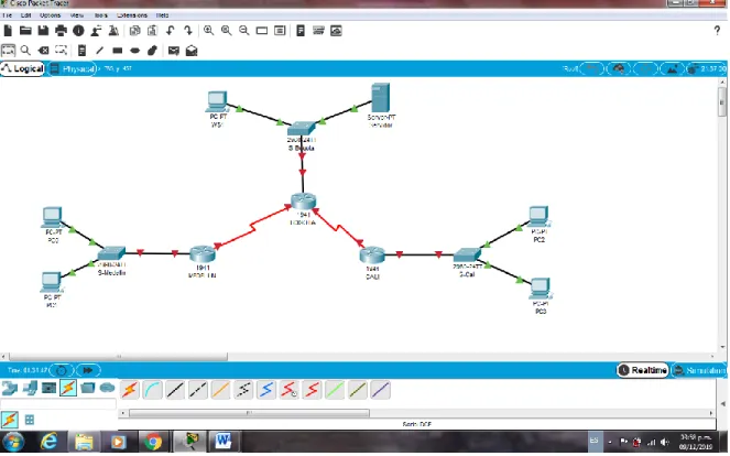
Figura 1. Modelo Topología de Red Escenario 1………..………….3
Figura 2. Conexión Física de los equipos con base en la Topología de Red………..…………6
Figura 3. Configuración Routers………..…………10
Figura 4. Comprobación Conectividad entre sí (PC0 al WS1, PC2, Servidor y PC3) -Exito………..17
Figura 5. Comprobación Conectividad entre sí (PC2 al Servidor, PC0 y WS1) – Éxito………18
Figura 6. Comprobación Conectividad entre sí (Servidor al R Bogotá, R Cali, R Medellín y PC0) Éxito………..19
Figura 7. Comprobación Conectividad entre sí (Servidor al PC2) Exito………..20
Figura 8. Comprobación Conectividad Telnet (Router Medellín a Router Cali) - Exito………..22
Figura 9. Comprobación Conectividad Telnet (WS-1 a Router Bogotá) – Se niega el acceso…….23
Figura 10. Comprobación Conectividad Telnet (Servidor a Router Cali) - Exito……….23
Figura 11. Comprobación Conectividad Telnet (Servidor a Router Medellin) - Exito……….24
Figura 12. Comprobación Conectividad (Servidor al Router Bogotá) - Exito………...25
Figura 13. Comprobación Conectividad (Servidor al Router Cali) - Exito……….25
Figura 14. Comprobación Conectividad (Servidor al Router Medellín) – Éxito………26
Figura 15. Comprobación Conectividad (Servidor al PC0) - Exito……….…26
Figura 16. Comprobación Conectividad (Servidor al PC2) – Éxito………27
Figura 17. Comprobación Conectividad (PC0 al Srevidor) - Exito……….28
Figura 18. Comprobación Conectividad (PC0 al PC2) - Se niega el acceso……….27
Figura 19. Comprobación Conectividad (PC3 al PC1) - Se niega el acceso……….…29
Figura 20. Comprobación Conectividad (PC3 al WS1) - Se niega el acceso………29
Figura 21. Comprobación Conectividad (PC3 al PC2) – Éxito………...……30
Figura 22. Comprobación listas de acceso Telnet (Router MEDELLIN - Router CALI) - Exito……31
Figura 23. Comprobación listas de acceso Telnet (WS_1 - Router BOGOTA) - Falla………..31
Figura 24. Comprobación listas de acceso Telnet (Servidor - Router Medellín) - Exito………32
Figura 25. Comprobación listas de acceso Telnet (PC0 al Router Cali) - Falla………..32
Figura 26. Comprobación listas de acceso Telnet (PC2 a Router Cali) Falla………..33
Figura 27. Comprobación listas de acceso Telnet (PC0 al Router Medellín) Falla……….33
Figura 28. Comprobación listas de acceso Telnet (PC2 al Router Medellín) Falla……….34
Figura 29. Comprobación listas de acceso Ping (PC2 al WS1) Falla………34
Figura 30. Comprobación listas de acceso Ping (PC0 al WS1) Falla………35
Figura 31. Comprobación listas de acceso Ping (PC0 al PC2) Falla………35
Figura 32. Comprobación listas de acceso Ping (PC2 al Servidor) Exito……….36
Figura 33. Comprobación listas de acceso Ping (PC0 al Servidor) Exito……….36
Figura 34. Comprobación listas de acceso Ping (Router Cali al PC0) Falla………37
Figura 35. Comprobación listas de acceso Ping (Router Medellin al PC2) Falla………37
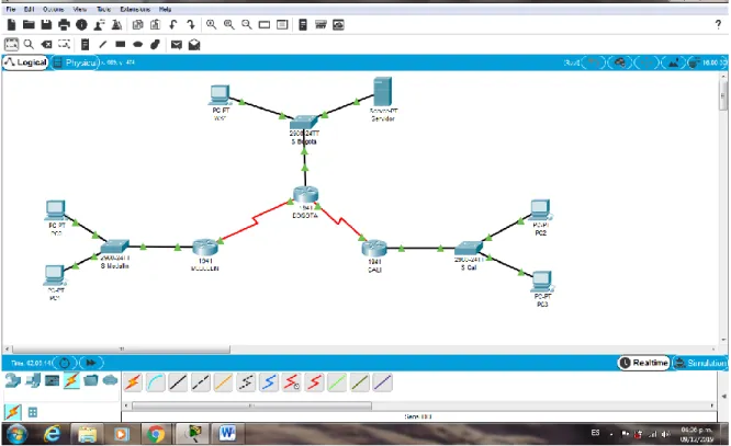
Figura 36. Modelo Topología Escenario 2……….38
Figura 37. Topología Escenario 2………39
Figura 38. Establecimiento de un servidor TFTP y almacenacmiento de los archivos de los routers………..52
Figura 39. Configuración DHCP PC0………...……….53
Figura 40. Configuración DHCP PC1………...……….54
Figura 41. Configuración DHCP PC2………...……….54
Figura 42. Configuración DHCP PC3………...……….55
Figura 43. Configuración DHCP PC4………...……….55
Figura 44. Configuración DHCP PC5………...…….56
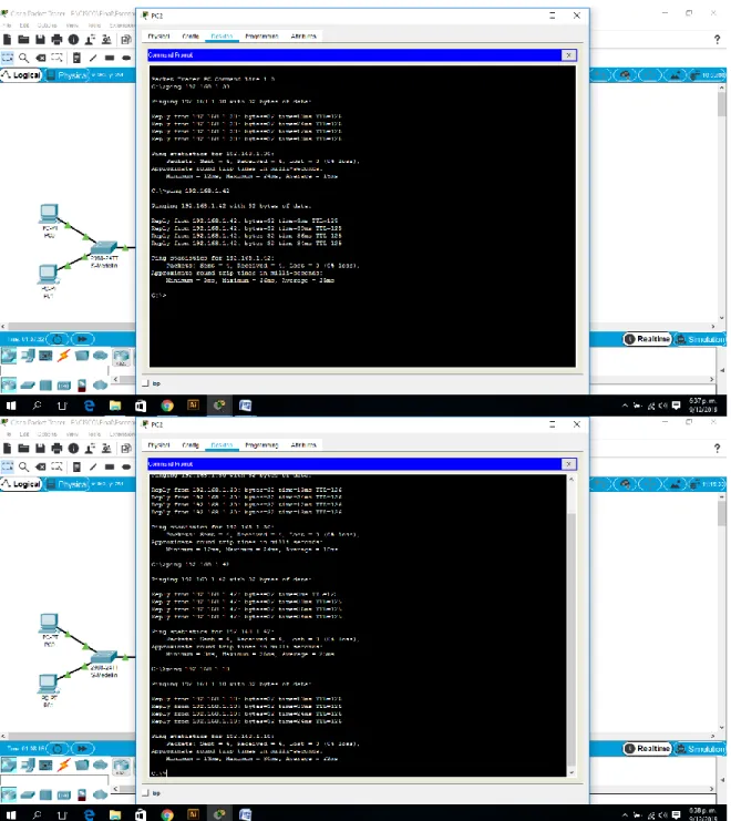
Figura 45. Comprobación ping a Servidor……….…….60
Figura 46. Comprobación ping NAT estático……….60
Figura 48. Comprobación ping PC0 a PC2………..62
Figura 49. Comprobación ping PC0 a PC3………..63
Figura 50. Comprobación ping PC0 a PC4………..63
Figura 51. Comprobación ping PC0 a PC5………..64
Figura 52. Comprobación ping PC0 a Servidor………..64
Figura 53. Comprobación ping VLAN 20 (PC4 a PC2) Exito……….……….65
Figura 54. Comprobación ping VLAN 20 (PC4 a Servidor) Se niega el acceso……….….66
Figura 55. Comprobación ping VLAN 10 (PC5 a PC2) Se niega el acceso……….……….67
Figura 56. Comprobación ping VLAN 10 (PC5 a Servidor Externo) Exito……….……….67
Figura 57. Comprobación ping VLAN 30 (PC3 a Servidor Externo) Se niega el acceso………68
Figura 58. Comprobación ftp VLAN 30 (PC3 a Servidor Externo) Exito……….………....69
Figura 59. Comprobación web VLAN 30 (PC3 a Servidor Externo) Exito……….………..69
Figura 60. Comprobación VLAN 20 (PC2 a PC4) Exito……….……….70
Figura 61. Comprobación VLAN 20 (PC2 a PC0) Exito……….……….71
Figura 62. Comprobación VLAN 30 (PC1 a Internet) Exito……….……….72
Figura 63. Comprobación VLAN 30 (PC1 a PC2) Se niega el acceso……….………..72
Figura 64. Comprobación VLAN 10 (PC0 a PC4) Exito……….……….73
Figura 65. Comprobación VLAN 10 (PC0 a PC2) Exito……….……….74
Figura 66. Comprobación VLAN 10 (PC0 a Web Inerno) Se niega el acceso……….……74
Figura 67. Comprobación VLAN 10 (PC0 a No Internet) Exito……….………...75
Figura 68. Comprobación una VLAN no pueden acceder a los de otra VLAN (PC4 a PC5) Exito...76
Figura 69. Comprobación una VLAN no pueden acceder a los de otra VLAN (PC4 a Web Interno) Exito……….……….77
Figura 70. Comprobación una VLAN no pueden acceder a los de otra VLAN (PC2 a PC3) Éxito...77
Figura 71. Comprobación una VLAN no pueden acceder a los de otra VLAN (PC0 a PC1) Éxito…..78
Figura 72. Comprobación VLAN administrativas y de la VLAN de servidores tienen accedo a los routers e internet (SW-Buc a Tunja) Exito……….………79
RESUMEN
Internet es la red más extensa que existe, la cual proporciona los servicios que permiten conectarnos, comunicarnos desde cualquier parte del mundo, desarrollar y facilitar el trabajo, las relaciones business-to-business, el comercio electrónico e
intereses personales, etc., pero también existen redes de todo tamaño que pueden ir desde redes simples, compuestas mínimo por dos PC, hasta redes que conectan millones de dispositivos.
La infraestructura de red es la plataforma que da soporte a la red, puede variar
ampliamente en términos de tamaño, cantidad de usuarios, y cantidad y tipo de servicios y la plataforma de routing y switching es la base de toda infraestructura en entornos de red de Cisco. Adicionalmente, las redes deben ser confiables, tolerantes a fallas, escalables, deben proporcionar calidad de servicio y garantizar la seguridad de la información y de los recursos en ellas.
ABSTRACT
The Internet is the most extensive network that exists, which provides the services that allow us to connect, communicate from anywhere in the world, develop and facilitate work, business-to-business relationships, electronic commerce and
personal interests, etc., but There are also networks of all sizes that can range from simple networks, composed of minimum for two PCs, to networks that connect millions of devices.
The network infrastructure is the platform that supports the network, it can vary in
terms of size, number of users, amount and type of services and the routing and switching platform is the basis of the entire infrastructure in Cisco network environments In addition, networks must be reliable, fault tolerant, scalable, must provide quality of service and ensure the security of information and resources in them.
INTRODUCCIÓN
En un mundo globalizado, donde la tencológia avanza a pasos agingatados, donde el uso de la internet permite extender y potenciar nuestra capacidad de comunicarnos sin límites, donde se producen las interacciones sociales, comerciales, políticas y personales que cambia en forma continua, por ende, se
dede estar al día con la evolución de esta red global.
Por lo tanto, los desarrolladores, programadores usan el internet como punto de inicio para sus esfuerzos, creando nuevos productos y servicios diseñados específicamente para aprovechar las funcionalidades de la red, en la medida que
estos impulsen los límites de lo posible, las funcionaliades de las redes interconectadas que crean la Internet jugarán un papel cada vez más grande en el éxito de los proyectos.
OBJETIVOS
GENERAL:
Identificar el grado de desarrollo de competencias y habilidades que fueron adquiridas a lo largo del Diplomado de Profundización CCNA, poniendo a prueba los niveles de comprensión y solción de dos problemas relacionados con diversos
aspectos de Networking.
ESPECÍFICOS:
Aplicar los conocimientos adquiridos durante del diplomado y desarrollar prueba de habilidades.
Desarrollar dos (2) escenarios propuestos, acompañado de los respectivos procesos de documentación de la solución.
Registrar en docuemento los correspondientes al registro de la
DESARROLLO DE LOS DOS ESCENARIOS
1. ESCENARIO 1
Una empresa posee sucursales distribuidas en las ciudades de Bogotá, Medellín y Cali en donde el estudiante será el administrador de la red, el cual deberá
configurar e interconectar entre sí cada uno de los dispositivos que forman parte del escenario, acorde con los lineamientos establecidos para el direccionamiento IP, protocolos de enrutamiento y demás aspectos que forman parte de la topología de red.
1.1. Topología de la Red
1.2. Configuración de equipos.
Realizar las rutinas de diagnóstico y dejar los equipos listos para su configuración (asignar nombres de equipos, asignar claves de seguridad, etc).
Configuracion Router – Bogota
Router>enable
Router#configure terminal
Enter configuration commands, one per line. End with CNTL/Z. Router(config)#hostname BOGOTA
BOGOTA(config)#no ip domain-lookup
BOGOTA(config)#service password-encryption BOGOTA(config)#enable secret class
BOGOTA(config)#banner motd #
Enter TEXT message. End with the character '#'. Acceso restringido.#
BOGOTA(config)#line console 0 BOGOTA(config-line)#password cisco BOGOTA(config-line)#login
BOGOTA(config-line)#logging synchronous BOGOTA(config-line)#line vty 0 15
BOGOTA(config-line)#password cisco BOGOTA(config-line)#logging synchronous BOGOTA(config-line)#login BOGOTA(config-line)#exit BOGOTA(config)#end BOGOTA#
%SYS-5-CONFIG_I: Configured from console by console
BOGOTA#copy running-config startup-config Destination filename [startup-config]?
Building configuration... [OK]
BOGOTA#
Configuracion Router – Medellin
Router>enable
Router#configure terminal
Enter configuration commands, one per line. End with CNTL/Z. Router(config)#hostname MEDELLIN
MEDELLIN(config)#no ip domain-lookup
MEDELLIN(config)#service password-encryption MEDELLIN(config)#enable secret class
MEDELLIN(config)#banner motd #
MEDELLIN(config)#line console 0 MEDELLIN(config-line)#password cisco MEDELLIN(config-line)#login
MEDELLIN(config-line)#logging synchronous MEDELLIN(config-line)#line vty 0 15
MEDELLIN(config-line)#password cisco MEDELLIN(config-line)#logging synchronous MEDELLIN(config-line)#login
MEDELLIN(config-line)#end MEDELLIN#
%SYS-5-CONFIG_I: Configured from console by console
MEDELLIN#copy running-config startup-config Destination filename [startup-config]?
Building configuration... [OK]
MEDELLIN#
Configuracion Router – Cali
Router>enable
Router#configure terminal
Enter configuration commands, one per line. End with CNTL/Z. Router(config)#hostname CALI
CALI(config)#no ip domain-lookup
CALI(config)#service password-encryption CALI(config)#enable secret class
CALI(config)#banner motd #
Enter TEXT message. End with the character '#'. Acceso restringido.#
CALI(config)#line console 0 CALI(config-line)#password cisco CALI(config-line)#login
CALI(config-line)#logging synchronous CALI(config-line)#line vty 0 15
CALI(config-line)#password cisco CALI(config-line)#logging synchronous CALI(config-line)#login
CALI(config-line)#end CALI#
%SYS-5-CONFIG_I: Configured from console by console
CALI#copy running-config startup-config Destination filename [startup-config]? Building configuration...
1.3. Conexión fisica de los equipos.
Realizar la conexión fisica de los equipos con base en la topología de red.
Dipositivos requeridos
3 Routers (cisco 1941) 3 Switch (cisco 2960-24TT) 1 Servidor
5 PCs con Windows 7 Cables Serial y Ethernet
Figura 2. Conexión Física de los equipos con base en la Topología de Red
1.4. Parte 1. Asignación de direcciones IP.
a. Se debe dividir (subnetear) la red creando una segmentación en ocho partes, para permitir crecimiento futuro de la red corporativa.
Tabla 1
Nombre de Subred Dirección de Red Máscara de Subred
Bogota LAN 192.168.1.0 255.255.255.224
Medellín LAN 192.168.1.32 255.255.255.224
Cali LAN 192.168.1.64 255.255.255.224
Bogota Medellín 192.168.1.96 255.255.255.224
Bogota Cali 192.168.1.128 255.255.255.224
Proxima 192.168.1.160 255.255.255.224
Proxima 192.168.1.192 255.255.255.224
Proxima 192.168.1.224 255.255.255.224
1.5. Parte 2. Configuración básica.
a. Completar la siguiente tabla con la configuración básica de los routers, teniendo en cuenta las subredes diseñadas.
Tabla 2
R1 R2 R3
Nombre de Host MEDELLIN BOGOTA CALI
Dirección de Ip en interfaz Serial 0/0
192.168.1.99 192.168.1.98 192.168.1.131
Dirección de Ip en interfaz Serial 0/1
192.168.1.130
Dirección de Ip en interfaz FA 0/0
192.168.1.33 192.168.1.1 192.168.1.65
Protocolo de enrutamiento
Eigrp Eigrp Eigrp
Sistema Autónomo 200 200 200
Afirmaciones de red 192.168.1.0 192.168.1.0 192.168.1.0
Configuración Router – Bogotá
BOGOTA#configure terminal
Enter configuration commands, one per line. End with CNTL/Z. BOGOTA(config)#int s0/0/0
BOGOTA(config-if)#ip address 192.168.1.98 255.255.255.224 BOGOTA(config-if)#no shutdown
BOGOTA(config-if)#int s0/0/1
BOGOTA(config-if)#no shutdown BOGOTA(config-if)#int g0/0
BOGOTA(config-if)#ip address 192.168.1.1 255.255.255.224 BOGOTA(config-if)#no shutdown
BOGOTA(config-if)#router eigrp 200
BOGOTA(config-router)#no auto-summary
BOGOTA(config-router)#do show ip route connected
C 192.168.1.0/27 is directly connected, GigabitEthernet0/0 C 192.168.1.96/27 is directly connected, Serial0/0/0
C 192.168.1.128/27 is directly connected, Serial0/0/1
BOGOTA(config-router)#network 192.168.1.0 0.0.0.31 BOGOTA(config-router)#network 192.168.1.96 0.0.0.31 BOGOTA(config-router)#
%DUAL-5-NBRCHANGE: IP-EIGRP 200: Neighbor 192.168.1.99 (Serial0/0/0) is up: new adjacency
BOGOTA(config-router)#network 192.168.1.128 0.0.0.31 BOGOTA(config-router)#
%DUAL-5-NBRCHANGE: IP-EIGRP 200: Neighbor 192.168.1.131 (Serial0/0/1) is up: new adjacency
BOGOTA(config-router)#
Configuration Router – Medellin
MEDELLIN>enable Password:
MEDELLIN#configure terminal
Enter configuration commands, one per line. End with CNTL/Z. MEDELLIN(config)#interface s0/0/0
MEDELLIN(config-if)#ip address 192.168.1.99 255.255.255.224 MEDELLIN(config-if)#no shutdown
MEDELLIN(config-if)#
%LINK-5-CHANGED: Interface Serial0/0/0, changed state to up MEDELLIN(config-if)#
%LINEPROTO-5-UPDOWN: Line protocol on Interface Serial0/0/0, changed state to up
MEDELLIN(config-if)#interface g0/0
MEDELLIN(config-if)#ip address 192.168.1.33 255.255.255.224 MEDELLIN(config-if)#no shutdown
MEDELLIN(config-if)#
MEDELLIN(config-if)#router eigrp 200
MEDELLIN(config-router)#no auto-summary
MEDELLIN(config-router)#do show ip route connected
C 192.168.1.32/27 is directly connected, GigabitEthernet0/0 C 192.168.1.96/27 is directly connected, Serial0/0/0
MEDELLIN(config-router)#network 192.168.1.32 0.0.0.31 MEDELLIN(config-router)#network 192.168.1.96 0.0.0.31 Medellin(config-router)#
%DUAL-5-NBRCHANGE: IP-EIGRP 200: Neighbor 192.168.1.98 (Serial0/0/0) is up: new adjacency
Configuration Router – Cali
CALI>enable Password:
CALI#configure terminal
Enter configuration commands, one per line. End with CNTL/Z. CALI(config)#interface s0/0/0
CALI(config-if)#ip address 192.168.1.131 255.255.255.224 CALI(config-if)#no shutdown
CALI(config-if)#
%LINK-5-CHANGED: Interface Serial0/0/0, changed state to up CALI(config-if)#
%LINEPROTO-5-UPDOWN: Line protocol on Interface Serial0/0/0, changed state to up
CALI(config-if)#interface g0/0
CALI(config-if)#ip address 192.168.1.65 255.255.255.224 CALI(config-if)#no shutdown
CALI(config-if)#
%LINK-5-CHANGED: Interface GigabitEthernet0/0, changed state to up %LINEPROTO-5-UPDOWN: Line protocol on Interface GigabitEthernet0/0, changed state to up
CALI(config-if)#router eigrp 200
CALI(config-router)#no auto-summary
CALI(config-router)#do show ip route connected
C 192.168.1.64/27 is directly connected, GigabitEthernet0/0 C 192.168.1.128/27 is directly connected, Serial0/0/0
CALI(config-router)#network 192.168.1.64 0.0.0.31
CALI(config-router)#network 192.168.1.128 0.0.0.31Cali(config-router)#
Figura 3. Configuración Routers
b. Después de cargada la configuración en los dispositivos, verificar la tabla de enrutamiento en cada uno de los routers para comprobar las redes y sus rutas.
BOGOTA>enable Password:
BOGOTA#show ip route
Codes: L - local, C - connected, S - static, R - RIP, M - mobile, B - BGP D - EIGRP, EX - EIGRP external, O - OSPF, IA - OSPF inter area N1 - OSPF NSSA external type 1, N2 - OSPF NSSA external type 2 E1 - OSPF external type 1, E2 - OSPF external type 2, E - EGP i - IS-IS, L1 - IS-IS level-1, L2 - IS-IS level-2, ia - IS-IS inter area * - candidate default, U - per-user static route, o - ODR
P - periodic downloaded static route
Gateway of last resort is not set
192.168.1.0/24 is variably subnetted, 6 subnets, 2 masks C 192.168.1.0/27 is directly connected, GigabitEthernet0/0 L 192.168.1.1/32 is directly connected, GigabitEthernet0/0 C 192.168.1.96/27 is directly connected, Serial0/0/0 L 192.168.1.98/32 is directly connected, Serial0/0/0 C 192.168.1.128/27 is directly connected, Serial0/0/1 L 192.168.1.130/32 is directly connected, Serial0/0/1
MEDELLIN>enable Password:
MEDELLIN#show ip route
Codes: L - local, C - connected, S - static, R - RIP, M - mobile, B - BGP D - EIGRP, EX - EIGRP external, O - OSPF, IA - OSPF inter area N1 - OSPF NSSA external type 1, N2 - OSPF NSSA external type 2 E1 - OSPF external type 1, E2 - OSPF external type 2, E - EGP i - IS-IS, L1 - IS-IS level-1, L2 - IS-IS level-2, ia - IS-IS inter area * - candidate default, U - per-user static route, o - ODR
P - periodic downloaded static route
Gateway of last resort is not set
192.168.1.0/24 is variably subnetted, 4 subnets, 2 masks C 192.168.1.32/27 is directly connected, GigabitEthernet0/0 L 192.168.1.33/32 is directly connected, GigabitEthernet0/0 C 192.168.1.96/27 is directly connected, Serial0/0/0
L 192.168.1.99/32 is directly connected, Serial0/0/0
MEDELLIN#
CALI#show ip route
Codes: L - local, C - connected, S - static, R - RIP, M - mobile, B - BGP D - EIGRP, EX - EIGRP external, O - OSPF, IA - OSPF inter area N1 - OSPF NSSA external type 1, N2 - OSPF NSSA external type 2 E1 - OSPF external type 1, E2 - OSPF external type 2, E - EGP i - IS-IS, L1 - IS-IS level-1, L2 - IS-IS level-2, ia - IS-IS inter area * - candidate default, U - per-user static route, o - ODR
P - periodic downloaded static route
Gateway of last resort is not set
192.168.1.0/24 is variably subnetted, 4 subnets, 2 masks C 192.168.1.64/27 is directly connected, GigabitEthernet0/0 L 192.168.1.65/32 is directly connected, GigabitEthernet0/0 C 192.168.1.128/27 is directly connected, Serial0/0/0
L 192.168.1.131/32 is directly connected, Serial0/0/0
CALI#
c. Verificar el balanceo de carga que presentan los routers.
BOGOTA>enable Password:
BOGOTA#show ip eigrp topology
IP-EIGRP Topology Table for AS 200/ID(192.168.1.130)
P 192.168.1.0/27, 1 successors, FD is 2816 via Connected, GigabitEthernet0/0
P 192.168.1.32/27, 1 successors, FD is 2170112 via 192.168.1.99 (2170112/2816), Serial0/0/0 P 192.168.1.64/27, 1 successors, FD is 2170112 via 192.168.1.131 (2170112/2816), Serial0/0/1 P 192.168.1.96/27, 1 successors, FD is 2169856 via Connected, Serial0/0/0
P 192.168.1.128/27, 1 successors, FD is 2169856 via Connected, Serial0/0/1
BOGOTA#show ip eigrp topology
MEDELLIN>enable Password:
MEDELLIN#show ip eigrp topology
IP-EIGRP Topology Table for AS 200/ID(192.168.1.99)
Codes: P - Passive, A - Active, U - Update, Q - Query, R - Reply, r - Reply status
P 192.168.1.0/27, 1 successors, FD is 2170112 via 192.168.1.98 (2170112/2816), Serial0/0/0 P 192.168.1.32/27, 1 successors, FD is 2816 via Connected, GigabitEthernet0/0
P 192.168.1.64/27, 1 successors, FD is 2682112 via 192.168.1.98 (2682112/2170112), Serial0/0/0 P 192.168.1.96/27, 1 successors, FD is 2169856 via Connected, Serial0/0/0
P 192.168.1.128/27, 1 successors, FD is 2681856 via 192.168.1.98 (2681856/2169856), Serial0/0/0 MEDELLIN#
CALI>enable Password:
CALI#show ip eigrp topology
IP-EIGRP Topology Table for AS 200/ID(192.168.1.131)
Codes: P - Passive, A - Active, U - Update, Q - Query, R - Reply, r - Reply status
P 192.168.1.0/27, 1 successors, FD is 2170112 via 192.168.1.130 (2170112/2816), Serial0/0/0 P 192.168.1.32/27, 1 successors, FD is 2682112
via 192.168.1.130 (2682112/2170112), Serial0/0/0 P 192.168.1.64/27, 1 successors, FD is 2816
via Connected, GigabitEthernet0/0
via 192.168.1.130 (2681856/2169856), Serial0/0/0 P 192.168.1.128/27, 1 successors, FD is 2169856 via Connected, Serial0/0/0
CALI#
d. Realizar un diagnóstico de vecinos usando el comando cdp.
BOGOTA>enable Password:
BOGOTA#show cdp neighbor
Capability Codes: R - Router, T - Trans Bridge, B - Source Route Bridge S - Switch, H - Host, I - IGMP, r - Repeater, P - Phone
Device ID Local Intrfce Holdtme Capability Platform Port ID Switch Gig 0/0 128 S 2960 Gig 0/1
CALI Ser 0/0/1 137 R C1900 Ser 0/0/0 MEDELLIN Ser 0/0/0 128 R C1900 Ser 0/0/0 BOGOTA#
MEDELLIN#show cdp neighbor
Capability Codes: R - Router, T - Trans Bridge, B - Source Route Bridge S - Switch, H - Host, I - IGMP, r - Repeater, P - Phone
Device ID Local Intrfce Holdtme Capability Platform Port ID Switch Gig 0/0 123 S 2960 Gig 0/1
BOGOTA Ser 0/0/0 130 R C1900 Ser 0/0/0 MEDELLIN#
apability Codes: R - Router, T - Trans Bridge, B - Source Route Bridge S - Switch, H - Host, I - IGMP, r - Repeater, P - Phone Device ID Local Intrfce Holdtme Capability Platform Port ID Switch Gig 0/0 144 S 2960 Gig 0/1
BOGOTA Ser 0/0/0 151 R C1900 Ser 0/0/1 CALI#
e. Realizar una prueba de conectividad en cada tramo de la ruta usando Ping.
MEDELLIN#ping 192.168.1.99 Type escape sequence to abort.
Sending 5, 100-byte ICMP Echos to 192.168.1.99, timeout is 2 seconds: !!!!!
Success rate is 100 percent (5/5), round-trip min/avg/max = 3/17/30 ms MEDELLIN#ping 192.168.1.131
Type escape sequence to abort.
Sending 5, 100-byte ICMP Echos to 192.168.1.131, timeout is 2 seconds: !!!!!
1.6. Parte 3. Configuration de enrutamiento.
a. Asignar el protocolo de enrutamiento EIGRP a los routers considerando el direccionamiento diseñado.
b. Verificar si existe vecindad con los routers configurados con EIGRP.
BOGOTA#show ip eigrp neighbor IP-EIGRP neighbors for process 200
H Address Interface Hold Uptime SRTT RTO Q Seq (sec) (ms) Cnt Num
0 192.168.1.99 Se0/0/0 14 00:24:38 40 1000 0 7 1 192.168.1.131 Se0/0/1 10 00:24:36 40 1000 0 7
MEDELLIN#show ip eigrp neighbor IP-EIGRP neighbors for process 200
H Address Interface Hold Uptime SRTT RTO Q Seq (sec) (ms) Cnt Num
0 192.168.1.98 Se0/0/0 11 00:25:18 40 1000 0 5
CALI#show ip eigrp neighbor
IP-EIGRP neighbors for process 200
H Address Interface Hold Uptime SRTT RTO Q Seq (sec) (ms) Cnt Num
0 192.168.1.130 Se0/0/0 11 00:26:06 40 1000 0 6
SHOW IP EIGRP TOPOLOGY
BOGOTA#show ip eigrp topology
IP-EIGRP Topology Table for AS 200/ID(192.168.1.130)
Codes: P - Passive, A - Active, U - Update, Q - Query, R - Reply, r - Reply status
P 192.168.1.0/27, 1 successors, FD is 2816 via Connected, GigabitEthernet0/0
P 192.168.1.32/27, 1 successors, FD is 2170112 via 192.168.1.99 (2170112/2816), Serial0/0/0 P 192.168.1.64/27, 1 successors, FD is 2170112 via 192.168.1.131 (2170112/2816), Serial0/0/1 P 192.168.1.96/27, 1 successors, FD is 2169856 via Connected, Serial0/0/0
P 192.168.1.128/27, 1 successors, FD is 2169856 via Connected, Serial0/0/1
IP-EIGRP Topology Table for AS 200/ID(192.168.1.99)
Codes: P - Passive, A - Active, U - Update, Q - Query, R - Reply, r - Reply status
P 192.168.1.0/27, 1 successors, FD is 2170112 via 192.168.1.98 (2170112/2816), Serial0/0/0 P 192.168.1.32/27, 1 successors, FD is 2816 via Connected, GigabitEthernet0/0
P 192.168.1.64/27, 1 successors, FD is 2682112 via 192.168.1.98 (2682112/2170112), Serial0/0/0 P 192.168.1.96/27, 1 successors, FD is 2169856 via Connected, Serial0/0/0
P 192.168.1.128/27, 1 successors, FD is 2681856 via 192.168.1.98 (2681856/2169856), Serial0/0/0
CALI#show ip eigrp topology
IP-EIGRP Topology Table for AS 200/ID(192.168.1.131)
Codes: P - Passive, A - Active, U - Update, Q - Query, R - Reply, r - Reply status
P 192.168.1.0/27, 1 successors, FD is 2170112 via 192.168.1.130 (2170112/2816), Serial0/0/0 P 192.168.1.32/27, 1 successors, FD is 2682112
via 192.168.1.130 (2682112/2170112), Serial0/0/0 P 192.168.1.64/27, 1 successors, FD is 2816
via Connected, GigabitEthernet0/0
P 192.168.1.96/27, 1 successors, FD is 2681856
via 192.168.1.130 (2681856/2169856), Serial0/0/0 P 192.168.1.128/27, 1 successors, FD is 2169856 via Connected, Serial0/0/0
c. Realizar la comprobación de las tablas de enrutamiento en cada uno de los routers para verificar cada una de las rutas establecidas.
BOGOTA#show ip route
Codes: L - local, C - connected, S - static, R - RIP, M - mobile, B - BGP D - EIGRP, EX - EIGRP external, O - OSPF, IA - OSPF inter area N1 - OSPF NSSA external type 1, N2 - OSPF NSSA external type 2 E1 - OSPF external type 1, E2 - OSPF external type 2, E - EGP i - IS-IS, L1 - IS-IS level-1, L2 - IS-IS level-2, ia - IS-IS inter area * - candidate default, U - per-user static route, o - ODR
P - periodic downloaded static route
Gateway of last resort is not set
C 192.168.1.0/27 is directly connected, GigabitEthernet0/0 L 192.168.1.1/32 is directly connected, GigabitEthernet0/0
D 192.168.1.32/27 [90/2170112] via 192.168.1.99, 00:33:17, Serial0/0/0 D 192.168.1.64/27 [90/2170112] via 192.168.1.131, 00:33:15, Serial0/0/1 C 192.168.1.96/27 is directly connected, Serial0/0/0
L 192.168.1.98/32 is directly connected, Serial0/0/0 C 192.168.1.128/27 is directly connected, Serial0/0/1 L 192.168.1.130/32 is directly connected, Serial0/0/1
MEDELLIN#show ip route
Codes: L - local, C - connected, S - static, R - RIP, M - mobile, B - BGP D - EIGRP, EX - EIGRP external, O - OSPF, IA - OSPF inter area N1 - OSPF NSSA external type 1, N2 - OSPF NSSA external type 2 E1 - OSPF external type 1, E2 - OSPF external type 2, E - EGP i - IS-IS, L1 - IS-IS level-1, L2 - IS-IS level-2, ia - IS-IS inter area * - candidate default, U - per-user static route, o - ODR
P - periodic downloaded static route
Gateway of last resort is not set
192.168.1.0/24 is variably subnetted, 7 subnets, 2 masks
D 192.168.1.0/27 [90/2170112] via 192.168.1.98, 00:34:11, Serial0/0/0 C 192.168.1.32/27 is directly connected, GigabitEthernet0/0
L 192.168.1.33/32 is directly connected, GigabitEthernet0/0
D 192.168.1.64/27 [90/2682112] via 192.168.1.98, 00:34:09, Serial0/0/0 C 192.168.1.96/27 is directly connected, Serial0/0/0
L 192.168.1.99/32 is directly connected, Serial0/0/0
D 192.168.1.128/27 [90/2681856] via 192.168.1.98, 00:34:11, Serial0/0/0
CALI#show ip route
Codes: L - local, C - connected, S - static, R - RIP, M - mobile, B - BGP D - EIGRP, EX - EIGRP external, O - OSPF, IA - OSPF inter area N1 - OSPF NSSA external type 1, N2 - OSPF NSSA external type 2 E1 - OSPF external type 1, E2 - OSPF external type 2, E - EGP i - IS-IS, L1 - IS-IS level-1, L2 - IS-IS level-2, ia - IS-IS inter area * - candidate default, U - per-user static route, o - ODR
P - periodic downloaded static route
Gateway of last resort is not set
192.168.1.0/24 is variably subnetted, 7 subnets, 2 masks
D 192.168.1.0/27 [90/2170112] via 192.168.1.130, 00:35:30, Serial0/0/0 D 192.168.1.32/27 [90/2682112] via 192.168.1.130, 00:35:30, Serial0/0/0 C 192.168.1.64/27 is directly connected, GigabitEthernet0/0
L 192.168.1.65/32 is directly connected, GigabitEthernet0/0
C 192.168.1.128/27 is directly connected, Serial0/0/0 L 192.168.1.131/32 is directly connected, Serial0/0/0
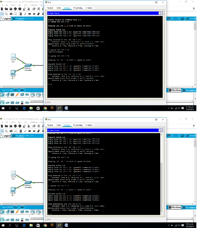
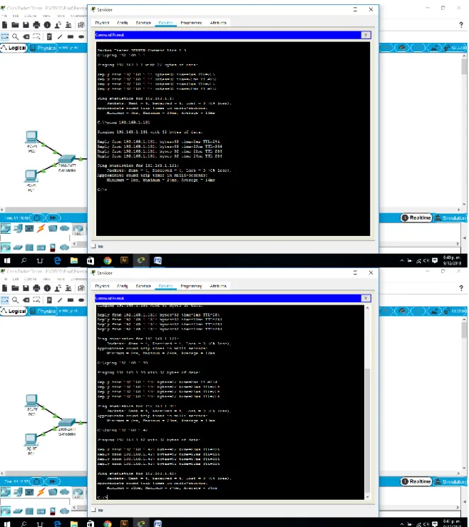
d. Realizar un diagnóstico para comprobar que cada uno de los puntos de la red se puedan ver y tengan conectividad entre sí. Realizar esta prueba desde un host de la red LAN del router CALI, primero a la red de MEDELLIN y luego al servidor.
Figura 7. Comprobación Conectividad entre sí (Servidor al PC2) Exito
1.7. Parte 4: Configuración de las listas de Control de Acceso.
En este momento cualquier usuario de la red tiene acceso a todos sus dispositivos y estaciones de trabajo. El jefe de redes le solicita implementar seguridad en la red. Para esta labor se decide configurar listas de control de acceso (ACL) a los routers.
Las condiciones para crear las ACL son las siguientes:
a. Cada router debe estar habilitado para establecer conexiones Telnet con los demás routers y tener acceso a cualquier dispositivo en la red.
Router>enable
Router#configure terminal
Enter configuration commands, one per line. End with CNTL/Z. Router(config)#hostname BOGOTA
BOGOTA(config)#no ip domain-lookup
BOGOTA(config)#service password-encryption BOGOTA(config)#enable secret class
BOGOTA(config)#banner motd #
Enter TEXT message. End with the character '#'. Acceso restringido.#
BOGOTA(config)#line console 0 BOGOTA(config-line)#password cisco BOGOTA(config-line)#login
BOGOTA(config-line)#logging synchronous BOGOTA(config-line)#line vty 0 15
BOGOTA(config-line)#logging synchronous BOGOTA(config-line)#login
BOGOTA(config-line)#exit BOGOTA(config)#end BOGOTA#
%SYS-5-CONFIG_I: Configured from console by console BOGOTA#copy running-config startup-config
Destination filename [startup-config]? Building configuration...
[OK]
BOGOTA#
Router>enable
Router#configure terminal
Enter configuration commands, one per line. End with CNTL/Z. Router(config)#hostname MEDELLIN
MEDELLIN(config)#no ip domain-lookup
MEDELLIN(config)#service password-encryption MEDELLIN(config)#enable secret class
MEDELLIN(config)#banner motd #
Enter TEXT message. End with the character '#'. Acceso restringido.#
MEDELLIN(config)#line console 0 MEDELLIN(config-line)#password cisco MEDELLIN(config-line)#login
MEDELLIN(config-line)#logging synchronous MEDELLIN(config-line)#line vty 0 15
MEDELLIN(config-line)#password cisco MEDELLIN(config-line)#logging synchronous MEDELLIN(config-line)#login
MEDELLIN(config-line)#end MEDELLIN#
%SYS-5-CONFIG_I: Configured from console by console MEDELLIN#copy running-config startup-config
Destination filename [startup-config]? Building configuration...
[OK]
MEDELLIN#
Router>enable
Router#configure terminal
Enter configuration commands, one per line. End with CNTL/Z. Router(config)#hostname CALI
CALI(config)#no ip domain-lookup
CALI(config)#service password-encryption CALI(config)#enable secret class
CALI(config)#banner motd #
Acceso restringido.#
CALI(config)#line console 0 CALI(config-line)#password cisco CALI(config-line)#login
CALI(config-line)#logging synchronous CALI(config-line)#line vty 0 15
CALI(config-line)#password cisco CALI(config-line)#logging synchronous CALI(config-line)#login
CALI(config-line)#end CALI#
%SYS-5-CONFIG_I: Configured from console by console CALI#copy running-config startup-config
Destination filename [startup-config]? Building configuration...
[OK] CALI#
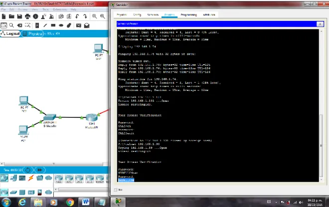
Figura 9. Comprobación Conectividad Telnet (WS-1 a Router Bogotá) – Se niega el acceso
Figura 11. Comprobación Conectividad Telnet (Servidor a Router Medellin) - Exito
b. El equipo WS1 y el servidor se encuentran en la subred de administración. Solo el servidor de la subred de administración debe tener acceso a cualquier otro dispositivo en cualquier parte de la red
BOGOTA>enable Password:
BOGOTA#configure terminal
Enter configuration commands, one per line. End with CNTL/Z. BOGOTA(config)#access-list 101 permit ip host 192.168.1.30 any BOGOTA(config)#int g0/0
Figura 12. Comprobación Conectividad (Servidor al Router Bogotá) - Exito
Figura 14. Comprobación Conectividad (Servidor al Router Medellín) – Éxito
Figura 16. Comprobación Conectividad (Servidor al PC2) - Exito
c. Las estaciones de trabajo en las LAN de MEDELLIN y CALI no deben tener acceso a ningún dispositivo fuera de su subred, excepto para interconectar con el servidor
MEDELLIN>enable Password:
MEDELLIN#configure terminal
Enter configuration commands, one per line. End with CNTL/Z.
MEDELLIN(config)#access-list 101 permit ip 192.168.1.32 0.0.0.31 host 192.168.1.3
MEDELLIN(config)#access-list 101 permit ip 192.168.1.32 0.0.0.31 host 192.168.1.30
MEDELLIN(config)#int g0/0
MEDELLIN(config-if)#ip access-group 101 in MEDELLIN(config-if)#
CALI>enable Password:
CALI#configure terminal
Enter configuration commands, one per line. End with CNTL/Z.
CALI(config)#access-list 101 permit ip 192.168.1.64 0.0.0.31 host 192.168.1.30 CALI(config)#int g0/0
Figura 17. Comprobación Conectividad (PC0 al Srevidor) - Exito
Figura 19. Comprobación Conectividad (PC3 al PC1) - Se niega el acceso
Figura 21. Comprobación Conectividad (PC3 al PC2) - Exito
1.8. Parte 5: Comprobación de la red instalada.
a. Se debe probar que la configuración de las listas de acceso fue exitosa.
b. Comprobar y Completar la siguiente tabla de condiciones de prueba para confirmar el óptimo funcionamiento de la red e.
ORIGEN DESTINO RESULTADO
TELNET
Router MEDELLIN Router CALI Éxito
WS_1 Router BOGOTA Falla
Servidor Router CALI Éxito
Servidor Router MEDELLIN Éxito
TELNET
LAN del Router MEDELLIN Router CALI Falla LAN del Router CALI Router CALI Falla LAN del Router MEDELLIN Router MEDELLIN Falla LAN del Router CALI Router MEDELLIN Falla
PING
LAN del Router CALI WS_1 Falla
LAN del Router MEDELLIN WS_1 Falla
LAN del Router MEDELLIN LAN del Router CALI Falla
PING
LAN del Router CALI Servidor Éxito
LAN del Router MEDELLIN Servidor Éxito Servidor LAN del Router MEDELLIN Éxito
Servidor LAN del Router CALI Éxito
Figura 22. Comprobación listas de acceso Telnet (Router MEDELLIN - Router CALI) - Exito
Figura 24. Comprobación listas de acceso Telnet (Servidor - Router Medellín) - Exito
Figura 26. Comprobación listas de acceso Telnet (PC2 a Router Cali) Falla
Figura 28. Comprobación listas de acceso Telnet (PC2 al Router Medellín) Falla
Figura 30. Comprobación listas de acceso Ping (PC0 al WS1) Falla
Figura 32. Comprobación listas de acceso Ping (PC2 al Servidor) Exito
Figura 34. Comprobación listas de acceso Ping (Router Cali al PC0) Falla
2. ESCENARIO 2
Una empresa tiene la conexión a internet en una red Ethernet, lo cual deben adaptarlo para facilitar que sus routers y las redes que incluyen puedan, por esa vía, conectarse a internet, pero empleando las direcciones de la red LAN original.
Desarrollo
Los siguientes son los requerimientos necesarios:
2.1. Todos los routers deberán tener lo siguiente:
• Configuración básica.
Figura 37. Topología Escenario 2
Router>en
Router#conf term
Enter configuration commands, one per line. End with CNTL/Z. Router(config)#no ip domain-lookup
Router(config)#service password-encryption
Router(config)#banner motd #ATENCION SOLO ACCESO AUTORIZADO!!# Router(config)#enable secret class
Router(config)#line console 0 Router(config-line)#password cisco Router(config-line)#login
Router(config-line)#logging synchronous Router(config-line)#line vty 0 15
Router(config-line)#password cisco Router(config-line)#login
Router(config-line)#logging synchronous Router(config-line)#hostname Bucaramanga Bucaramanga(config)#int g0/0.1
Bucaramanga(config-subif)#encapsulation dot1q 1
Bucaramanga(config-subif)#ip address 172.31.2.1 255.255.255.248 Bucaramanga(config-subif)#int g0/0.10
Bucaramanga(config-subif)#encapsulation dot1q 10
Bucaramanga(config-subif)#ip address 172.31.0.1 255.255.255.192 Bucaramanga(config-subif)#int g0/0.30
Bucaramanga(config-subif)#ip address 172.31.0.65 255.255.255.192 Bucaramanga(config-subif)#int g0/0
Bucaramanga(config-if)#no shutdown
Bucaramanga(config-if)#
%LINK-5-CHANGED: Interface GigabitEthernet0/0, changed state to up
%LINEPROTO-5-UPDOWN: Line protocol on Interface GigabitEthernet0/0, changed state to up
%LINK-5-CHANGED: Interface GigabitEthernet0/0.1, changed state to up
%LINEPROTO-5-UPDOWN: Line protocol on Interface GigabitEthernet0/0.1, changed state to up
%LINK-5-CHANGED: Interface GigabitEthernet0/0.10, changed state to up
%LINEPROTO-5-UPDOWN: Line protocol on Interface GigabitEthernet0/0.10, changed state to up
%LINK-5-CHANGED: Interface GigabitEthernet0/0.30, changed state to up
%LINEPROTO-5-UPDOWN: Line protocol on Interface GigabitEthernet0/0.30, changed state to up
Bucaramanga(config-if)#int s0/0/0
Bucaramanga(config-if)#ip address 172.31.2.34 255.255.255.252 Bucaramanga(config-if)#no shutdown
%LINK-5-CHANGED: Interface Serial0/0/0, changed state to down Bucaramanga(config-if)#router ospf 1
Bucaramanga(config-router)#do show ip route connected C 172.31.0.0/26 is directly connected, GigabitEthernet0/0.10 C 172.31.0.64/26 is directly connected, GigabitEthernet0/0.30 C 172.31.2.0/29 is directly connected, GigabitEthernet0/0.1
Bucaramanga(config-router)#network 172.31.0.0 0.0.0.63 area 0 Bucaramanga(config-router)#network 172.31.0.64 0.0.0.63 area 0 Bucaramanga(config-router)#network 172.31.2.0 0.0.0.7 area 0 Bucaramanga(config-router)#network 172.31.2.32 0.0.0.3 area 0 Bucaramanga(config-router)#
Bucaramanga(config-router)#exit Bucaramanga(config)#exit
Bucaramanga#
%SYS-5-CONFIG_I: Configured from console by console
Bucaramanga#show ip route
N1 - OSPF NSSA external type 1, N2 - OSPF NSSA external type 2 E1 - OSPF external type 1, E2 - OSPF external type 2, E - EGP i - IS-IS, L1 - IS-IS level-1, L2 - IS-IS level-2, ia - IS-IS inter area * - candidate default, U - per-user static route, o - ODR
P - periodic downloaded static route
Gateway of last resort is not set
172.31.0.0/16 is variably subnetted, 6 subnets, 3 masks C 172.31.0.0/26 is directly connected, GigabitEthernet0/0.10 L 172.31.0.1/32 is directly connected, GigabitEthernet0/0.10 C 172.31.0.64/26 is directly connected, GigabitEthernet0/0.30 L 172.31.0.65/32 is directly connected, GigabitEthernet0/0.30 C 172.31.2.0/29 is directly connected, GigabitEthernet0/0.1 L 172.31.2.1/32 is directly connected, GigabitEthernet0/0.1
Bucaramanga#
Router>en
Router#conf term
Enter configuration commands, one per line. End with CNTL/Z. Router(config)#no ip domain-lookup
Router(config)#service password-encryption
Router(config)#banner motd #ATENCION SOLO ACCESO AUTORIZADO!!# Router(config)#enable secret class
Router(config)#line console 0 Router(config-line)#password cisco Router(config-line)#login
Router(config-line)#logging synchronous Router(config-line)#line vty 0 15
Router(config-line)#password cisco Router(config-line)#login
Router(config-line)#logging synchronous Router(config-line)#hostname Tunja Tunja(config)#int g0/0.1
Tunja(config-subif)#encapsulation dot1q 1
Tunja(config-subif)#ip address 172.3.2.9 255.255.255.248 Tunja(config-subif)#int g0/0.20
Tunja(config-subif)#encapsulation dot1q 20
Tunja(config-subif)#ip address 172.31.0.129 255.255.255.192 Tunja(config-subif)#int g0/0.30
Tunja(config-subif)#encapsulation dot1q 30
Tunja(config-subif)#ip address 172.31.0.193 255.255.255.192 Tunja(config-subif)#int g0/0
Tunja(config-if)#no shutdown
Tunja(config-if)#
%LINEPROTO-5-UPDOWN: Line protocol on Interface GigabitEthernet0/0, changed state to up
%LINK-5-CHANGED: Interface GigabitEthernet0/0.1, changed state to up
%LINEPROTO-5-UPDOWN: Line protocol on Interface GigabitEthernet0/0.1, changed state to up
%LINK-5-CHANGED: Interface GigabitEthernet0/0.20, changed state to up
%LINEPROTO-5-UPDOWN: Line protocol on Interface GigabitEthernet0/0.20, changed state to up
%LINK-5-CHANGED: Interface GigabitEthernet0/0.30, changed state to up
%LINEPROTO-5-UPDOWN: Line protocol on Interface GigabitEthernet0/0.30, changed state to up
Tunja(config-if)#int s0/0/0
Tunja(config-if)#ip address 172.31.2.33 255.255.255.252 Tunja(config-if)#no shutdown
Tunja(config-if)#
%LINK-5-CHANGED: Interface Serial0/0/0, changed state to up
Tunja(config-if)#
%LINEPROTO-5-UPDOWN: Line protocol on Interface Serial0/0/0, changed state to up
Tunja(config-if)#int s0/0/1
Tunja(config-if)#ip address 172.31.2.37 255.255.255.252 Tunja(config-if)#no shutdown
%LINK-5-CHANGED: Interface Serial0/0/1, changed state to down Tunja(config-if)#exit
Tunja(config)#int g0/1
Tunja(config-if)#ip address 209.165.220.1 255.255.255.0 Tunja(config-if)#no shutdown
Tunja(config-if)#
%LINK-5-CHANGED: Interface GigabitEthernet0/1, changed state to up
%LINEPROTO-5-UPDOWN: Line protocol on Interface GigabitEthernet0/1, changed state to up
Tunja(config-if)#router ospf 1
Tunja(config-router)#do show ip route connected
C 172.31.0.128/26 is directly connected, GigabitEthernet0/0.20 C 172.31.0.192/26 is directly connected, GigabitEthernet0/0.30 C 172.31.2.32/30 is directly connected, Serial0/0/0
C 209.165.220.0/24 is directly connected, GigabitEthernet0/1
Tunja(config-router)#network 172.3.2.8 0.0.0.7 area 0 Tunja(config-router)#network 172.31.0.128 0.0.0.63 area 0 Tunja(config-router)#network 172.31.0.192 0.0.0.63 area 0 Tunja(config-router)#network 172.31.2.32 0.0.0.3 area 0 Tunja(config-router)#
01:39:40: %OSPF-5-ADJCHG: Process 1, Nbr 172.31.2.34 on Serial0/0/0 from LOADING to FULL, Loading Done
Tunja(config-router)#network 172.31.2.36 0.0.0.3 area 0 Tunja(config-router)#exit
Tunja(config)#exit Tunja#
%SYS-5-CONFIG_I: Configured from console by console
Tunja#show ip route
Codes: L - local, C - connected, S - static, R - RIP, M - mobile, B - BGP D - EIGRP, EX - EIGRP external, O - OSPF, IA - OSPF inter area N1 - OSPF NSSA external type 1, N2 - OSPF NSSA external type 2 E1 - OSPF external type 1, E2 - OSPF external type 2, E - EGP i - IS-IS, L1 - IS-IS level-1, L2 - IS-IS level-2, ia - IS-IS inter area * - candidate default, U - per-user static route, o - ODR
P - periodic downloaded static route
Gateway of last resort is not set
172.3.0.0/16 is variably subnetted, 2 subnets, 2 masks C 172.3.2.8/29 is directly connected, GigabitEthernet0/0.1 L 172.3.2.9/32 is directly connected, GigabitEthernet0/0.1 172.31.0.0/16 is variably subnetted, 9 subnets, 4 masks
O 172.31.0.0/26 [110/65] via 172.31.2.34, 00:01:36, Serial0/0/0 O 172.31.0.64/26 [110/65] via 172.31.2.34, 00:01:36, Serial0/0/0 C 172.31.0.128/26 is directly connected, GigabitEthernet0/0.20 L 172.31.0.129/32 is directly connected, GigabitEthernet0/0.20 C 172.31.0.192/26 is directly connected, GigabitEthernet0/0.30 L 172.31.0.193/32 is directly connected, GigabitEthernet0/0.30 O 172.31.2.0/29 [110/65] via 172.31.2.34, 00:01:36, Serial0/0/0 C 172.31.2.32/30 is directly connected, Serial0/0/0
L 172.31.2.33/32 is directly connected, Serial0/0/0
209.165.220.0/24 is variably subnetted, 2 subnets, 2 masks C 209.165.220.0/24 is directly connected, GigabitEthernet0/1 L 209.165.220.1/32 is directly connected, GigabitEthernet0/1
Router>en
Router#conf term
Enter configuration commands, one per line. End with CNTL/Z. Router(config)#no ip domain-lookup
Router(config)#service password-encryption
Router(config)#banner motd #ATENCION SOLO ACCESO AUTORIZADO!!# Router(config)#enable secret class
Router(config)#line console 0 Router(config-line)#password cisco Router(config-line)#login
Router(config-line)#logging synchronous Router(config-line)#line vty 0 15
Router(config-line)#password cisco Router(config-line)#login
Router(config-line)#logging synchronous Router(config-line)#hostname Cundinamarca Cundinamarca(config)#int g0/0.1
Cundinamarca(config-subif)#encapsulation dot1q 1
Cundinamarca(config-subif)#ip address 172.31.2.9 255.255.255.248 Cundinamarca(config-subif)#int g0/0.20
Cundinamarca(config-subif)#encapsulation dot1q 20
Cundinamarca(config-subif)#ip address 172.31.1.65 255.255.255.192 Cundinamarca(config-subif)#int g0/0.30
Cundinamarca(config-subif)#encapsulation dot1q 30
Cundinamarca(config-subif)#ip address 172.31.1.1 255.255.255.192 Cundinamarca(config-subif)#int g0/0.88
Cundinamarca(config-subif)#encapsulation dot1q 88
Cundinamarca(config-subif)#ip address 172.31.2.25 255.255.255.248 Cundinamarca(config-subif)#int g0/0
Cundinamarca(config-if)#no shutdown
Cundinamarca(config-if)#
%LINK-5-CHANGED: Interface GigabitEthernet0/0, changed state to up
%LINEPROTO-5-UPDOWN: Line protocol on Interface GigabitEthernet0/0, changed state to up
%LINK-5-CHANGED: Interface GigabitEthernet0/0.1, changed state to up
%LINEPROTO-5-UPDOWN: Line protocol on Interface GigabitEthernet0/0.1, changed state to up
%LINEPROTO-5-UPDOWN: Line protocol on Interface GigabitEthernet0/0.20, changed state to up
%LINK-5-CHANGED: Interface GigabitEthernet0/0.30, changed state to up
%LINEPROTO-5-UPDOWN: Line protocol on Interface GigabitEthernet0/0.30, changed state to up
%LINK-5-CHANGED: Interface GigabitEthernet0/0.88, changed state to up
%LINEPROTO-5-UPDOWN: Line protocol on Interface GigabitEthernet0/0.88, changed state to up
Cundinamarca(config-if)#int s0/0/0
Cundinamarca(config-if)#ip address 172.31.2.38 255.255.255.252 Cundinamarca(config-if)#no shutdown
Cundinamarca(config-if)#
%LINK-5-CHANGED: Interface Serial0/0/0, changed state to up
Cundinamarca(config-if)#
%LINEPROTO-5-UPDOWN: Line protocol on Interface Serial0/0/0, changed state to up
Cundinamarca(config-if)#exit
Cundinamarca(config)#router ospf 1
Cundinamarca(config-router)#do show ip route connected C 172.31.1.0/26 is directly connected, GigabitEthernet0/0.30 C 172.31.1.64/26 is directly connected, GigabitEthernet0/0.20 C 172.31.2.8/29 is directly connected, GigabitEthernet0/0.1 C 172.31.2.24/29 is directly connected, GigabitEthernet0/0.88 C 172.31.2.36/30 is directly connected, Serial0/0/0
Cundinamarca(config-router)#network 172.31.1.0 0.0.0.63 area 0 Cundinamarca(config-router)#network 172.31.1.64 0.0.0.63 area 0 Cundinamarca(config-router)#network 172.31.2.8 0.0.0.7 area 0 Cundinamarca(config-router)#network 172.31.2.24 0.0.0.7 area 0 Cundinamarca(config-router)#network 172.31.2.36 0.0.0.3 area 0 Cundinamarca(config-router)#
02:08:05: %OSPF-5-ADJCHG: Process 1, Nbr 209.165.220.1 on Serial0/0/0 from LOADING to FULL, Loading Done
Cundinamarca(config-router)#exit Cundinamarca(config)#exit
%SYS-5-CONFIG_I: Configured from console by console
Cundinamarca#show ip route
Codes: L - local, C - connected, S - static, R - RIP, M - mobile, B - BGP D - EIGRP, EX - EIGRP external, O - OSPF, IA - OSPF inter area N1 - OSPF NSSA external type 1, N2 - OSPF NSSA external type 2 E1 - OSPF external type 1, E2 - OSPF external type 2, E - EGP i - IS-IS, L1 - IS-IS level-1, L2 - IS-IS level-2, ia - IS-IS inter area * - candidate default, U - per-user static route, o - ODR
P - periodic downloaded static route
Gateway of last resort is not set
172.3.0.0/29 is subnetted, 1 subnets
O 172.3.2.8/29 [110/65] via 172.31.2.37, 00:00:51, Serial0/0/0 172.31.0.0/16 is variably subnetted, 16 subnets, 4 masks
O 172.31.0.0/26 [110/129] via 172.31.2.37, 00:00:51, Serial0/0/0 O 172.31.0.64/26 [110/129] via 172.31.2.37, 00:00:51, Serial0/0/0 O 172.31.0.128/26 [110/65] via 172.31.2.37, 00:00:51, Serial0/0/0 O 172.31.0.192/26 [110/65] via 172.31.2.37, 00:00:51, Serial0/0/0 C 172.31.1.0/26 is directly connected, GigabitEthernet0/0.30 L 172.31.1.1/32 is directly connected, GigabitEthernet0/0.30 C 172.31.1.64/26 is directly connected, GigabitEthernet0/0.20 L 172.31.1.65/32 is directly connected, GigabitEthernet0/0.20 O 172.31.2.0/29 [110/129] via 172.31.2.37, 00:00:51, Serial0/0/0 C 172.31.2.8/29 is directly connected, GigabitEthernet0/0.1 L 172.31.2.9/32 is directly connected, GigabitEthernet0/0.1 C 172.31.2.24/29 is directly connected, GigabitEthernet0/0.88 L 172.31.2.25/32 is directly connected, GigabitEthernet0/0.88 O 172.31.2.32/30 [110/128] via 172.31.2.37, 00:00:51, Serial0/0/0 C 172.31.2.36/30 is directly connected, Serial0/0/0
L 172.31.2.38/32 is directly connected, Serial0/0/0
Cundinamarca#
Switch>en
Switch#conf term
Enter configuration commands, one per line. End with CNTL/Z. Switch(config)#hostname SW-Buc
SW-Buc(config)#vlan 1 SW-Buc(config-vlan)#vlan 10 SW-Buc(config-vlan)#vlan 30 SW-Buc(config-vlan)#int f0/1
SW-Buc(config-if)#int f0/4
SW-Buc(config-if)#switchport mode access SW-Buc(config-if)#switchport access vlan 30 SW-Buc(config-if)#int g0/1
SW-Buc(config-if)#switchport mode trunk
SW-Buc(config-if)#
%LINEPROTO-5-UPDOWN: Line protocol on Interface GigabitEthernet0/1, changed state to down
%LINEPROTO-5-UPDOWN: Line protocol on Interface GigabitEthernet0/1, changed state to up
SW-Buc(config-if)#exit SW-Buc(config)#int vlan 1
SW-Buc(config-if)#ip address 172.31.2.3 255.255.255.248 SW-Buc(config-if)#no shutdown
SW-Buc(config-if)#
%LINK-5-CHANGED: Interface Vlan1, changed state to up
%LINEPROTO-5-UPDOWN: Line protocol on Interface Vlan1, changed state to up
SW-Buc(config-if)#ip default-gateway 172.31.2.1 SW-Buc(config)#
Switch>en
Switch#conf term
Enter configuration commands, one per line. End with CNTL/Z. Switch(config)#hostname SW-Tun
SW-Tun(config)#vlan 1 SW-Tun(config-vlan)#vlan 20 SW-Tun(config-vlan)#vlan 30 SW-Tun(config-vlan)#int f0/1
SW-Tun(config-if)#switchport mode access SW-Tun(config-if)#switchport access vlan 20 SW-Tun(config-if)#int f0/4
SW-Tun(config-if)#switchport mode access SW-Tun(config-if)#switchport access vlan 30 SW-Tun(config-if)#int g0/1
SW-Tun(config-if)#switchport mode trunk
SW-Tun(config-if)#
%LINEPROTO-5-UPDOWN: Line protocol on Interface GigabitEthernet0/1, changed state to up
SW-Tun(config-if)#exit SW-Tun(config)#int vlan 1
SW-Tun(config-if)#ip address 172.3.2.11 255.255.255.248 SW-Tun(config-if)#no shutdown
SW-Tun(config-if)#
%LINK-5-CHANGED: Interface Vlan1, changed state to up
%LINEPROTO-5-UPDOWN: Line protocol on Interface Vlan1, changed state to up
SW-Tun(config-if)#ip default-gateway 172.3.2.9 SW-Tun(config)#
Switch>en
Switch#conf term
Enter configuration commands, one per line. End with CNTL/Z. Switch(config)#hostname SW-Cun SW-Cun(config)#vlan 1 SW-Cun(config-vlan)#vlan 20 SW-Cun(config-vlan)#vlan 30 SW-Cun(config-vlan)#vlan 88 SW-Cun(config-vlan)#exit SW-Cun(config)#int f0/1
SW-Cun(config-if)#switchport mode access SW-Cun(config-if)#switchport access vlan 20 SW-Cun(config-if)#int f0/4
SW-Cun(config-if)#switchport mode access SW-Cun(config-if)#switchport access vlan 30 SW-Cun(config-if)#int f0/24
SW-Cun(config-if)#switchport mode access SW-Cun(config-if)#switchport access vlan 88 SW-Cun(config-if)#int g0/1
SW-Cun(config-if)#switchport mode trunk
SW-Cun(config-if)#
%LINEPROTO-5-UPDOWN: Line protocol on Interface GigabitEthernet0/1, changed state to down
SW-Cun(config-if)#exit SW-Cun(config)#int vlan 1
SW-Cun(config-if)#ip address 172.31.2.11 255.255.255.248 SW-Cun(config-if)#no shutdown
SW-Cun(config-if)#
%LINK-5-CHANGED: Interface Vlan1, changed state to up
%LINEPROTO-5-UPDOWN: Line protocol on Interface Vlan1, changed state to up
SW-Cun(config-if)#ip default-gateway 172.31.2.9 SW-Cun(config)#
• Autenticación local con AAA.
Bucaramanga>en
Bucaramanga(config)#username admin secret admin123 Bucaramanga(config)#aaa new-model
Bucaramanga(config)#aaa authentication login AUTHLOCAL local Bucaramanga(config)#line console 0
Bucaramanga(config-line)#login authentication AUTHLOCAL Bucaramanga(config-line)#line vty 0 15
Bucaramanga(config-line)#login authentication AUTHLOCAL Bucaramanga(config-line)#
Tunja(config)#username admin secret admin123 Tunja(config)#aaa new-model
Tunja(config)#aaa authentication login AUTHLOCAL local Tunja(config)#line console 0
Tunja(config-line)#login authentication AUTHLOCAL Tunja(config-line)#line vty 0 15
Tunja(config-line)#login authentication AUTHLOCAL Tunja(config-line)#
Cundinamarca(config)#username admin secret admin123 Cundinamarca(config)#aaa new-model
Cundinamarca(config)#aaa authentication login AUTHLOCAL local Cundinamarca(config)#line console 0
Cundinamarca(config-line)#login authentication AUTHLOCAL Cundinamarca(config-line)#line vty 0 15
• Cifrado de contraseñas.
Router>en Router#conf t
Enter configuration commands, one per line. End with CNTL/Z. Router(config)#no ip domain-lookup
Router(config)#service password-encryption
Router(config)#banner motd #Acceso restringido!# Router(config)#enable secret class
Router(config)#line console 0 Router(config-line)#password cisco Router(config-line)#login
Router(config-line)#logging synchronous Router(config-line)#line vty 0 15
Router(config-line)#password cisco Router(config-line)#login Router(config-line)#logging synchronous Router(config-line)#hostname Bucaramanga Bucaramanga(config)# Router>en Router#conf t
Enter configuration commands, one per line. End with CNTL/Z. Router(config)#no ip domain-lookup
Router(config)#service password-encryption
Router(config)#banner motd #Acceso restringido!# Router(config)#enable secret class
Router(config)#line console 0 Router(config-line)#password cisco Router(config-line)#login
Router(config-line)#logging synchronous Router(config-line)#line vty 0 15
Router(config-line)#password cisco Router(config-line)#login Router(config-line)#logging synchronous Router(config-line)#hostname Tunja Tunja(config)# Router>en Router#conf t
Enter configuration commands, one per line. End with CNTL/Z. Router(config)#no ip domain-lookup
Router(config)#service password-encryption
Router(config)#banner motd #Acceso restringido!# Router(config)#enable secret class
Router(config-line)#login
Router(config-line)#logging synchronous Router(config-line)#line vty 0 15
Router(config-line)#password cisco Router(config-line)#login
Router(config-line)#logging synchronous Router(config-line)#hostname Cundinamarca Cundinamarca(config)#
Un máximo de internos para acceder al router.
Bucaramanga(config-line)#login block-for 10 attempts 3 within 60
Tunja(config-line)#login block-for 10 attempts 3 within 60
Cundinamarca(config-line)#login block-for 10 attempts 3 within 60
• Máximo tiempo de acceso al detectar ataques.
Bucaramanga(config-line)#login block-for 10 attempts 3 within 60
Tunja(config-line)#login block-for 10 attempts 3 within 60
Cundinamarca(config-line)#login block-for 10 attempts 3 within 60
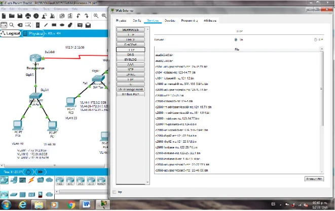
• Establezca un servidor TFTP y almacene todos los archivos
Figura 38. Establecimiento de un servidor TFTP y almacenacmiento de los archivos de los routers
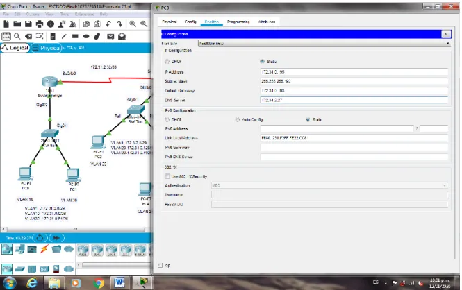
2.2. El DHCP deberá proporcionar solo direcciones a los hosts de
Bucaramanga y Cundinamarca
Tunja(config)#ip dhcp excluded-address 172.31.0.1 172.31.0.2 Tunja(config)#ip dhcp excluded-address 172.31.0.65 172.31.0.66 Tunja(config)#ip dhcp excluded-address 172.31.1.65 172.31.1.66 Tunja(config)#ip dhcp excluded-address 172.31.1.1 172.31.1.2 Tunja(config)#ip dhcp pool VLAN10BUC
Tunja(dhcp-config)#network 172.31.0.0 255.255.255.192 Tunja(dhcp-config)#default-router 172.31.0.1
Tunja(dhcp-config)#dns-server 172.31.2.27 Tunja(dhcp-config)#ip dhcp pool VLAN30BUC
Tunja(dhcp-config)#network 172.31.0.64 255.255.255.192 Tunja(dhcp-config)#default-router 172.31.0.65
Tunja(dhcp-config)#dns-server 172.31.2.27 Tunja(dhcp-config)#ip dhcp pool VLAN20CUN
Tunja(dhcp-config)#network 172.31.1.64 255.255.255.192 Tunja(dhcp-config)#default-router 172.31.1.65
Tunja(dhcp-config)#dns-server 172.31.2.27 Tunja(dhcp-config)#ip dhcp pool VLAN30CUN
Tunja(dhcp-config)#network 172.31.1.0 255.255.255.192 Tunja(dhcp-config)#default-router 172.31.1.1
Bucaramanga(config)#int g0/0.10
Bucaramanga(config-subif)#ip helper-address 172.31.2.33 Bucaramanga(config-subif)#int g0/0.30
Bucaramanga(config-subif)#ip helper-address 172.31.2.33 Bucaramanga(config-subif)#
Cundinamarca(config)#int g0/0.20
Cundinamarca(config-subif)#ip helper-address 172.31.2.37 Cundinamarca(config-subif)#int g0/0.30
Cundinamarca(config-subif)#ip helper-address 172.31.2.37 Cundinamarca(config-subif)#
Figura 40. Configuración DHCP PC1
Figura 42. Configuración DHCP PC3
Figura 44. Configuración DHCP PC5
2.3. El web server deberá tener NAT estático y el resto de los equipos de la
topología emplearan NAT de sobrecarga (PAT).
Tunja(config)#ip dhcp excluded-address 172.31.0.1 172.31.0.2 Tunja(config)#ip dhcp excluded-address 172.31.0.65 172.31.0.66 Tunja(config)#ip dhcp excluded-address 172.31.1.65 172.31.1.66 Tunja(config)#ip dhcp excluded-address 172.31.1.1 172.31.1.2 Tunja(config)#ip dhcp pool VLAN10BUC
Tunja(dhcp-config)#network 172.31.0.0 255.255.255.192 Tunja(dhcp-config)#default-router 172.31.0.1
Tunja(dhcp-config)#dns-server 172.31.2.27 Tunja(dhcp-config)#ip dhcp pool VLAN30BUC
Tunja(dhcp-config)#network 172.31.0.64 255.255.255.192 Tunja(dhcp-config)#default-router 172.31.0.65
Tunja(dhcp-config)#dns-server 172.31.2.27 Tunja(dhcp-config)#ip dhcp pool VLAN20CUN
Tunja(dhcp-config)#network 172.31.1.64 255.255.255.192 Tunja(dhcp-config)#default-router 172.31.1.65
Tunja(dhcp-config)#dns-server 172.31.2.27 Tunja(dhcp-config)#ip dhcp pool VLAN30CUN
Tunja(dhcp-config)#network 172.31.1.0 255.255.255.192 Tunja(dhcp-config)#default-router 172.31.1.1
Tunja con0 is now available Press RETURN to get started. Acceso restringido!
User Access Verification
Tunja(config)#ip nat inside source static 172.31.2.27 209.165.220.3 Tunja(config)#access-list 1 permit 172.0.0.0 0.255.255.255
Tunja(config)#ip nat inside source list 1 interface g0/1 overload Tunja(config)#int g0/1
Tunja(config-if)#ip nat outside Tunja(config-if)#int g0/0.1
Tunja(config-subif)#ip nat inside Tunja(config-subif)#int g0/0.20 Tunja(config-subif)#ip nat inside Tunja(config-subif)#int g0/0.30 Tunja(config-subif)#ip nat inside Tunja(config-subif)#int s0/0/0 Tunja(config-if)#ip nat inside Tunja(config-if)#int s0/0/1 Tunja(config-if)#ip nat inside Tunja(config-if)#exit
Tunja(config)#ip route 0.0.0.0 0.0.0.0 209.165.220.2 Tunja(config)#router ospf 1
Tunja(config-router)#default-information originate Tunja(config-router)#exit
Tunja(config)#exit
Tunja#show ip route
Codes: L - local, C - connected, S - static, R - RIP, M - mobile, B - BGP D - EIGRP, EX - EIGRP external, O - OSPF, IA - OSPF inter area N1 - OSPF NSSA external type 1, N2 - OSPF NSSA external type 2 E1 - OSPF external type 1, E2 - OSPF external type 2, E - EGP i - IS-IS, L1 - IS-IS level-1, L2 - IS-IS level-2, ia - IS-IS inter area * - candidate default, U - per-user static route, o - ODR
P - periodic downloaded static route
Gateway of last resort is 209.165.220.2 to network 0.0.0.0
L 172.31.0.193/32 is directly connected, GigabitEthernet0/0.30 O 172.31.1.0/26 [110/65] via 172.31.2.38, 04:08:55, Serial0/0/1 O 172.31.1.64/26 [110/65] via 172.31.2.38, 04:08:55, Serial0/0/1 O 172.31.2.0/29 [110/65] via 172.31.2.34, 01:28:55, Serial0/0/0 O 172.31.2.8/29 [110/65] via 172.31.2.38, 04:08:55, Serial0/0/1 O 172.31.2.24/29 [110/65] via 172.31.2.38, 04:08:55, Serial0/0/1 C 172.31.2.32/30 is directly connected, Serial0/0/0
L 172.31.2.33/32 is directly connected, Serial0/0/0 C 172.31.2.36/30 is directly connected, Serial0/0/1 L 172.31.2.37/32 is directly connected, Serial0/0/1
209.165.220.0/24 is variably subnetted, 2 subnets, 2 masks C 209.165.220.0/24 is directly connected, GigabitEthernet0/1 L 209.165.220.1/32 is directly connected, GigabitEthernet0/1 S* 0.0.0.0/0 [1/0] via 209.165.220.2
Tunja#
Bucaramanga#show ip route
Codes: L - local, C - connected, S - static, R - RIP, M - mobile, B - BGP D - EIGRP, EX - EIGRP external, O - OSPF, IA - OSPF inter area N1 - OSPF NSSA external type 1, N2 - OSPF NSSA external type 2 E1 - OSPF external type 1, E2 - OSPF external type 2, E - EGP i - IS-IS, L1 - IS-IS level-1, L2 - IS-IS level-2, ia - IS-IS inter area * - candidate default, U - per-user static route, o - ODR
P - periodic downloaded static route
Gateway of last resort is 172.31.2.33 to network 0.0.0.0
172.3.0.0/29 is subnetted, 1 subnets
O 172.3.2.8/29 [110/65] via 172.31.2.33, 01:24:08, Serial0/0/0 172.31.0.0/16 is variably subnetted, 15 subnets, 4 masks C 172.31.0.0/26 is directly connected, GigabitEthernet0/0.10 L 172.31.0.1/32 is directly connected, GigabitEthernet0/0.10 C 172.31.0.64/26 is directly connected, GigabitEthernet0/0.30 L 172.31.0.65/32 is directly connected, GigabitEthernet0/0.30 O 172.31.0.128/26 [110/65] via 172.31.2.33, 01:24:08, Serial0/0/0 O 172.31.0.192/26 [110/65] via 172.31.2.33, 01:24:08, Serial0/0/0 O 172.31.1.0/26 [110/129] via 172.31.2.33, 01:24:08, Serial0/0/0 O 172.31.1.64/26 [110/129] via 172.31.2.33, 01:24:08, Serial0/0/0 C 172.31.2.0/29 is directly connected, GigabitEthernet0/0.1
L 172.31.2.1/32 is directly connected, GigabitEthernet0/0.1 O 172.31.2.8/29 [110/129] via 172.31.2.33, 01:24:08, Serial0/0/0 O 172.31.2.24/29 [110/129] via 172.31.2.33, 01:24:08, Serial0/0/0 C 172.31.2.32/30 is directly connected, Serial0/0/0
L 172.31.2.34/32 is directly connected, Serial0/0/0
O 172.31.2.36/30 [110/128] via 172.31.2.33, 01:24:08, Serial0/0/0 O*E2 0.0.0.0/0 [110/1] via 172.31.2.33, 00:08:56, Serial0/0/0