DIPLOMADO DE PROFUNDIZACIÓN CISCO PRUEBA DE HABILIDADES PRÁCTICAS CISCO CCNP
DAVID GALLEGO SUÁREZ
UNIVERSIDAD NACIONAL ABIERTA Y A DISTANCIA – UNAD
ESCUELA DE CIENCIAS BÁSICAS, TECNOLOGÍA E INGENIERÍA – ECBTI INGENIERÍA ELECTRÓNICA
DIPLOMADO DE PROFUNDIZACION CISCO PRUEBA DE HABILIDADES PRÁCTICAS CISCO CCNP
DAVID GALLEGO SUÁREZ
Diplomado de opción de grado presentado para optar el título de INGENIERO ELECTRÓNICO
DIRECTOR:
MSc. GERARDO GRANADOS ACUÑA
UNIVERSIDAD NACIONAL ABIERTA Y A DISTANCIA – UNAD
ESCUELA DE CIENCIAS BÁSICAS, TECNOLOGÍA E INGENIERÍA – ECBTI INGENIERÍA ELECTRÓNICA
3
NOTA DE ACEPTACIÓN:
Presidente del Jurado
Jurado
Jurado
4
DEDICATORIA
Esta actividad corresponde a la parte final de mi proceso académico en la ingeniería electrónica, así que agradezco a toda mi familia que siempre creyó y me acompaño en este camino educativo, principalmente a mis padres Iván Manuel y Dora luz por su constante cariño y paciencia. A mi hermano Cesar por ser un referente a seguir e inspiración.
También quiero agradecer a mi amigo Juan David que ha me ha brindado su valiosa amistad y ha compartido este proceso académico junto a mí.
5 CONTENIDO
LISTA DE ILUSTRACIONES ... 6
LISTA DE TABLAS ... 9
GLOSARIO ... 10
RESUMEN ... 11
ABSTRACT……….11
INTRODUCCIÓN ... 12
DESCRIPCIÓN DE ESCENARIOS ... 13
1. Escenario 1 ... 13
1.1. Parte 1: Configuración del escenario propuesto. ... 14
1.2. Parte 2: Verificar conectividad de red y control de la trayectoria. ... 28
2. Escenario 2 ... 35
2.1. Parte 1: Configurar la red de acuerdo con las especificaciones. ... 36
2.2. Parte 2: conectividad de red de prueba y las opciones configuradas. ... 72
CONCLUSIONES ... 79
6
LISTA DE ILUSTRACIONES
Ilustración 1. Topología de red ……….……...13
Ilustración 2. Topología de red Packet Tracer ……… ………...13
Ilustración 3.Configuración interface Router 1 ………...14
Ilustración 4. Configuración interface Router 2………..16
Ilustración 5. Configuración interface Router 3 ……….…17
Ilustración 6. Configuración de la interface R1, R2 y R3 ………..…17
Ilustración 7. Ancho de banda router Cali ……….18
Ilustración 8. Ancho de banda router Ocaña ……….…18
Ilustración 9. Ancho de banda router Barranquilla ………...19
Ilustración 10. Configuración de dirección OSPFv3 R2 ………..20
Ilustración 11. Configuración de dirección OSPFv3 R2 ………..21
Ilustración 12. Configuración de OSPF y conexión serial en R2 ………...22
Ilustración 12. Configuración de interfaz y conexión serial en OSPF área 0 ...23
Ilustración 13. Configuración del área 1 totalmente Stubby ………..24
Ilustración 14. Propagación de rutas por defecto ………...……...24
Ilustración 15. Configuración EIGRP para IPv4 ………....25
Ilustración 16. Configuración EIGRP para IPv4 ………25
Ilustración 17. Configuración EIGRP para IPv6 ………26
Ilustración 18. Configuración de interfaces pasivas para EIGRP ……….…..26
Ilustración 19. Redistribución mutua entre OSPF y EIGRP ……….27
Ilustración 20. Lista de distribución y ACL ……….28
Ilustración 21. Tabla de enrutamiento Router 1 Cali ………28
Ilustración 22. Tabla de enrutamiento Router 2 Ocana ………...29
Ilustración 23. Tabla de enrutamiento Router 3 Barranquilla ……….……….30
Ilustración 24. Verificación de comunicación entre routers ……….31
Ilustración 25. Verificación de comunicación entre routers ……….31
Ilustración 26. Verificación de comunicación entre routers ……….32
Ilustración 27. Verificación de las rutas R1 ………32
Ilustración 28. Verificación de las rutas R2 ………33
Ilustración 29. Verificación de las rutas R3 ………33
Ilustración 30. Topología de red ……….35
Ilustración 31. Topología de red Packet Tracer ………...35
Ilustración 32. Apagando Interface ASL1 ………...36
Ilustración 33. Apagando Interface ASL2 ………..37
Ilustración 34. Apagando Interface DSL1 ………..38
Ilustración 35. Apagando Interface DSL2 ………..39
Ilustración 36. Interface apagada ASL1 ………....40
Ilustración 37. Interface apagada ASL2 ………....40
Ilustración 38. Interface apagada DSL1 ………....41
Ilustración 39. Interface apagada DSL2 ……….41
Ilustración 40. Todas las interfaces apagadas ………..…...42
7
Ilustración 42. Asignación de nombre al Switch 2 ………...43
Ilustración 43. Asignación de nombre al Switch 3 ………..….43
Ilustración 44. Asignación de nombre al Switch 4 ………...44
Ilustración 45. Conexión EtherChannel DSL1 ………..…44
Ilustración 46. Conexión EtherChannel DSL2 ………..…45
Ilustración 47. Mostrar EtherChannel DSL1 ………...46
Ilustración 48. Mostrar EtherChannel DSL2 ………...46
Ilustración 49. Port-channel utilizando LACP desde el DSL1 ………..…..47
Ilustración 50. Port-channel utilizando LACP desde el ASL1 ………..48
Ilustración 51. Port-channel utilizando LACP desde el DSL2 ………...49
Ilustración 52. Port-channel utilizando LACP desde el ASL2 ………..…...49
Ilustración 53. Port-channels en las interfaces Fa0/7 y Fa0/8 utilizan LACP ………50
Ilustración 54. Port-channel utilizando PAgP desde el DSL1 ………....50
Ilustración 55. Port-channel utilizando PAgP desde el ASL1 ………....51
Ilustración 56. Port-channel utilizando PAgP desde el DSL2 ………..…..52
Ilustración 57. Port-channel utilizando PAgP desde el ASL2 ………....53
Ilustración 58. Port-channels en las interfaces F0/9 y fa0/10 utilizan PAgP ……...53
Ilustración 59. Configuración de puertos troncales en DSL1 ………..54
Ilustración 60. Configuración de puertos troncales en DSL2 ………...55
Ilustración 61. Configuración de puertos troncales en ASL1 ………...56
Ilustración 62. Configuración de puertos troncales en ASL2 ………...57
Ilustración 63. Todos los puertos troncales asignados ………. …...57
Ilustración 64. Configuración DSL1 para utilizar VTP ………...58
Ilustración 65. Configuración ASL1 para utilizar VTP ………...58
Ilustración 66. Configuración ASL2 para utilizar VTP ………..59
Ilustración 67. Configuración DSL1 como servidor ………...59
Ilustración 68. Configuración ASL1 como cliente VTP ……….59
Ilustración 69. Visualizar ASL1 como cliente VTP ………....60
Ilustración 70. Configuración ASL2 como cliente VTP ………....60
Ilustración 71. Configuración del número y nombre de las VLANS ………..62
Ilustración 72. Visualización de las VLANS ………62
Ilustración 73. Suspender la VLAN 434 ………..63
Ilustración 74. Configuración de las VLAN en DSL2 ………64
Ilustración 75. Suspender VLAN 434 en DLS2 ………..64
Ilustración 76. VLAN con el nombre CONTABILIDAD ……….65
Ilustración 77 Limitación de los puertos truncales en las vlan 67 ………..65
Ilustración 78. Configuración Spanning tree root en DSL1 ……….65
Ilustración 79. Configuración Spanning tree root en DSL2 ……….66
Ilustración 80. Configuración de troncales en DSL1 ………66
Ilustración 81. Configuración de troncales en DSL2 ………67
Ilustración 82. Configuración de troncales en ASL1 ………68
Ilustración 83. Configuración de troncales en ASL2 ………69
Ilustración 84. Configuración de la interface en DSL1 ………70
Ilustración 85. Configuración de la interface en DSL2 ……….70
8
Ilustración 87. Configuración de la interface en ASL2 ……….71
Ilustración 88. Mostrar VLAN en DSL1 ………..72
Ilustración 89. Mostrar VLAN en DSL2 ………..73
Ilustración 90. Mostrar VLAN en ASL1 ………..74
Ilustración 91. Mostrar VLAN en ASL2 ………..74
Ilustración 92. Mostrar interface troncal en DSL1 ………75
Ilustración 93. Mostrar interface troncal en ASL2 ……….75
Ilustración 94. Verificación del EtherChannel en DLS1 ………...76
Ilustración 95. Verificación del EtherChannel en ASL1 ………...76
Ilustración 96. Verificación del Spanning tree en DSL1 ………..77
Ilustración 97. Verificación del Spanning tree en DSL2 ………..78
9
LISTA DE TABLAS
Tabla 1. Visualización del número y nombre de las VLANS ...61
Tabla 2. Visualización del nuevo número y nombre de las VLANS ...61
Tabla 3. Visualización de las interfaces asignadas a las VLAN ………..69
10 GLOSARIO
CCNP: (Cisco Certified Network Professional) Curso de capacitación en redes informáticas a través de hardware y software de la empresa Cisco.
Packet Tracer: Software de simulación implementado por Cisco para facilitar el diseño y la experimentación de las distintas topologías de red.
Networking: En redes de comunicación este concepto hace énfasis en la transmisión de datos entre dispositivos informáticos.
Protocolos de red: Son los modelos o las formas con las que se implementan un sistema de comunicación entre partes, con el propósito de transmitir información basadas en tecnologías de redes.
11 RESUMEN
La realización de esta actividad se basó en dos escenarios de implementación de redes el primero enfocado en el desarrollo y configuración de routers en ciudades alejadas, el segundo es un escenario centralizado en usuarios que poseen su propio servidor y que se interconectan con switches.
Como evidencia del correcto avance y utilización del software packet tracer se agregan los códigos y la verificación de las listas de configuración que genera el sistema, la capturas del paso a paso de la actividad y la descripción de hechos relevantes para un buen entendimiento.
Palabras claves: Router, Switch, Packet Tracer, Códigos Cisco.
ABSTRACT
The realization of this activity was based on two network implementation scenarios, the first focused on the development and configuration of routers in remote cities, the second is a centralized scenario for users who own their own server and who interconnect with switches.
As evidence of the correct progress and use of the packet tracer software, the codes and the verification of the configuration lists generated by the system, the step-by-step captures of the activity and the description of relevant facts for a good understanding are added.
12
INTRODUCCIÓN
Esta actividad de pruebas de habilidades prácticas de CISCO CCNP, se presenta con dos escenarios de redes donde se detalla el tipo de montaje y los datos relevantes para la configuración de cada uno de ellos. La importancia de definir escenarios basados en redes de comunicación entre empresas internas y externas, para entender sus aplicaciones y la implementación de redes en distintos escenarios.
En cada una de las configuraciones que respecta a los routers y switches se utiliza una serie de códigos que permite establecer las interfaces, rutas y protocolos que definen una comunicación y una estabilidad en el envió de datos a través de la red. El propósito de los dos escenarios propuestos es reconocer los modelos de red como alternativas de aprendizaje y practica conforme a lo estudiado en el curso diplomado de profundización cisco ccnp. Logrando captar en estos dos escenarios la importancia de las redes en la actualidad.
La metodología implementada en el desarrollo de esta actividad ayuda a entender de manera secuencial y ordenada a aplicar y entender la configuración del funcionamiento de las redes, diferenciando la fuente del código como un texto propio de los sistemas de cisco y la captura de imágenes como demostración práctica de lo desarrollado.
El conocimiento adquirido en la elaboración de los ejercicios planteados es
importante en distintas áreas de la ingeniería, para poder entender aplicaciones de comunicación de datos a través de la red y reconocer dispositivos para la
13
DESCRIPCIÓN DE ESCENARIOS
1. Escenario 1
Una empresa de confecciones posee tres sucursales distribuidas en las ciudades de Cali, Barranquilla y Ocaña, en donde el estudiante será el administrador de la red, el cual deberá configurar e interconectar entre sí cada uno de los dispositivos que forman parte del escenario, acorde con los lineamientos establecidos para el direccionamiento IP, protocolos de enrutamiento y demás aspectos que forman parte de la topología de red.
Topología de red
Ilustración 1. Topología de red
Configurar la topología de red, de acuerdo con las siguientes especificaciones.
14
1.1 Parte 1: Configuración del escenario propuesto
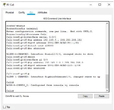
1. Configurar las interfaces con las direcciones IPv4 e IPv6 que se muestran en la topología de red.
Cali
Router>enable
Router#config terminal
Enter configuration commands, one per line. End with CNTL/Z. Router(config)#hostname Cali
Cali(config)#interface serial 0/0/0
Cali(config-if)#ip addres 192.168.9.1 255.255.255.252 Cali(config-if)#ipv6 address 2001:DB8:ACAD:90::1/64 Cali(config-if)#clock rate 128000
Cali(config-if)#no shutdown
%LINK-5-CHANGED: Interface Serial0/0/0, changed state to down Cali(config-if)#exit
Cali(config)#interface gi 0/0
Cali(config-if)#ip address 192.168.110.1 255.255.255.0 Cali(config-if)#ipv6 address 2001:DB8:ACAD:110::1/64 Cali(config-if)#no shutdown
Cali(config-if)#
%LINK-5-CHANGED: Interface GigabitEthernet0/0, changed state to up
15 Ocaña
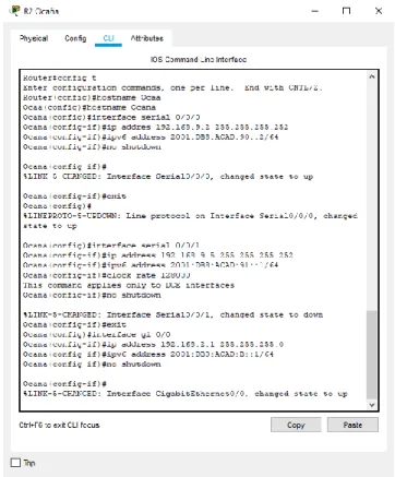
Router#config t
Enter configuration commands, one per line. End with CNTL/Z. Router(config)#hostname Ocaa
Ocaa(config)#hostname Ocana Ocana(config)#interface serial 0/0/0
Ocana(config-if)#ip addres 192.168.9.2 255.255.255.252 Ocana(config-if)#ipv6 address 2001:DB8:ACAD:90::2/64 Ocana(config-if)#no shutdown
Ocana(config-if)#
%LINK-5-CHANGED: Interface Serial0/0/0, changed state to up Ocana(config-if)#exit
Ocana(config)#
%LINEPROTO-5-UPDOWN: Line protocol on Interface Serial0/0/0, changed state to up
Ocana(config)#interface serial 0/0/1
Ocana(config-if)#ip address 192.168.9.5 255.255.255.252 Ocana(config-if)#ipv6 address 2001:DB8:ACAD:91::1/64 Ocana(config-if)#clock rate 128000
This command applies only to DCE interfaces Ocana(config-if)#no shutdown
%LINK-5-CHANGED: Interface Serial0/0/1, changed state to down Ocana(config-if)#exit
Ocana(config)#interface gi 0/0
Ocana(config-if)#ip address 192.168.2.1 255.255.255.0 Ocana(config-if)#ipv6 address 2001:DB8:ACAD:B::1/64 Ocana(config-if)#no shutdown
Ocana(config-if)#
16
Ilustración 4. Configuración interface Router 2 Barranquilla
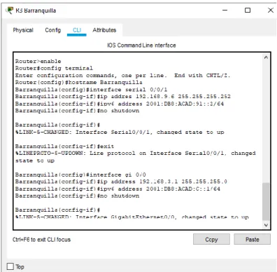
Router>enable
Router#config terminal
Enter configuration commands, one per line. End with CNTL/Z. Router(config)#hostname Barranquilla
Barranquilla(config)#interface serial 0/0/1
Barranquilla(config-if)#ip addres 192.168.9.6 255.255.255.252 Barranquilla(config-if)#ipv6 address 2001:DB8:ACAD:91::2/64 Barranquilla(config-if)#no shutdown
Barranquilla(config-if)#
%LINK-5-CHANGED: Interface Serial0/0/1, changed state to up Barranquilla(config-if)#exit
%LINEPROTO-5-UPDOWN: Line protocol on Interface Serial0/0/1, changed state to up
Barranquilla(config)#interface gi 0/0
17 Barranquilla(config-if)#
%LINK-5-CHANGED: Interface GigabitEthernet0/0, changed state to up
Ilustración 5. Configuración interface Router 3
18
2. Ajustar el ancho de banda a 128 kbps sobre cada uno de los enlaces seriales ubicados en R1, R2, y R3 y ajustar la velocidad de reloj de las conexiones de DCE según sea apropiado.
Cali
Cali>enable Cali#config t
Enter configuration commands, one per line. End with CNTL/Z. Cali(config)#interface serial 0/0/0
Cali(config-if)#band % Incomplete command.
Cali(config-if)#bandwidth 128000 Cali(config-if)#
Cali#
Ilustración 7. Ancho de banda router Cali
Ocaña
Ocana>enable Ocana#config t
Enter configuration commands, one per line. End with CNTL/Z. Ocana(config)#interface serial 0/0/0
Ocana(config-if)#bandwidth 128000 Ocana(config-if)#
19 Barranquilla
Barranquilla>enable Barranquilla#config t
Enter configuration commands, one per line. End with CNTL/Z. Barranquilla(config)#interface serial 0/0/0
Barranquilla(config-if)#bandwidth 128000 Barranquilla(config-if)#exit
Barranquilla(config)#int gi 0/0
Barranquilla(config-if)#bandwidth 128000 Barranquilla(config-if)#
Ilustración 9. Ancho de banda router Barranquilla
3. En R2 y R3 configurar las familias de direcciones OSPFv3 para IPv4 e IPv6. Utilice el identificador de enrutamiento 2.2.2.2 en R2 y 3.3.3.3 en R3 para ambas familias de direcciones.
Ocana(config)#ipv6 unicast-routing Ocana(config)#router ospfv3 1
Ocana(config-router)#address-family ipv4 unicast Ocana(config-router-af)#router-id 2.2.2.2
Ocana(config-router-af)#exit
Ocana(config-router)#address-family ipv6 unicast Ocana(config-router-af)#router-id 2.2.2.2
Ocana(config-router-af)#exit-address-family Ocana(config-router)#exit
20
Ilustración 10. Configuración de dirección OSPFv3 R2
Barranquilla(config)#ipv6 unicast-routing Barranquilla(config)#router ospfv3 1
Barranquilla(config-router)#address-family ipv4 unicast Barranquilla(config-router-af)#router-id 3.3.3.3
Barranquilla(config-router-af)#passive-interface g0/0 Barranquilla(config-router-af)#exit-address-family Barranquilla(config-router)#address-family ipv6 unicast Barranquilla(config-router-af)#router-id 3.3.3.3
21
22
4. En R2, configurar la interfaz F0/0 en el área 1 de OSPF y la conexión serial entre R2 y R3 en OSPF área 0.
Ocana#config t
Enter configuration commands, one per line. End with CNTL/Z. Ocana(config)#router ospf 1
Ocana(config-router)#network 192.168.2.0 0.0.0.255 area 1 Ocana(config-router)#network 192.168.9.4 0.0.0.3 area 0 Ocana(config-router)#exit
Ocana(config)#ipv6 unicast-routing Ocana(config)#ipv6 router ospf 1 Ocana(config-rtr)#router-id 2.2.2.2 Ocana(config-rtr)#exit
Ocana(config)#int gi 0/0
Ocana(config-if)#ipv6 ospf 1 area 1 Ocana(config-if)#no shutdown Ocana(config-if)#exit
Ocana(config)#interface serial 0/0/1 Ocana(config-if)#ipv6 ospf 1 area 0 Ocana(config-if)#no shutdown Ocana(config-if)#exit
Ocana(config)#
23
5. En R3, configurar la interfaz F0/0 y la conexión serial entre R2 y R3 en OSPF área 0.
Barranquilla(config)#router ospf 1
Barranquilla(config-router)#network 192.168.3.0 0.0.0.255 area 0 Barranquilla(config-router)#network 192.168.9.4 0.0.0.3 area 0 Barranquilla(config-router)#ipv6 unicast-routing
Barranquilla(config)#ipv6 router ospf 1 Barranquilla(config-rtr)#router-id 3.3.3.3 Barranquilla(config-rtr)#exit
Barranquilla(config)#int gi 0/0
Barranquilla(config-if)#ipv6 ospf 1 area 0 Barranquilla(config-if)#no shutdown Barranquilla(config-if)#exit
Barranquilla(config)#interface serial 0/0/1 Barranquilla(config-if)#ipv6 ospf 1 area 0 Barranquilla(config-if)#no shutdown Barranquilla(config-if)#exit
01:16:34: %OSPF-5-ADJCHG: Process 1, Nbr 192.168.9.5 on Serial0/0/1 from LOADING to FULL, Loading Done
01:16:34: %OSPFv3-5-ADJCHG: Process 1, Nbr 2.2.2.2 on Serial0/0/1 from LOADING to FULL, Loading Done
24
6. Configurar el área 1 como un área totalmente Stubby.
R2 Ocaña Ocana>enable
Ocana#config terminal
Enter configuration commands, one per line. End with CNTL/Z. Ocana(config)#router ospf 1
Ocana(config-router)#router ospf 1
Ocana(config-router)#area 1 stub no-summary Ocana(config-router)#
Ilustración 13. Configuración del área 1 totalmente Stubby
7. Propagar rutas por defecto de IPv4 y IPv6 en R3 al interior del dominio OSPFv3. Nota: Es importante tener en cuenta que una ruta por defecto es diferente a la definición de rutas estáticas.
R3 Barranquilla
Barranquilla(config)#ipv6 route ::/0 2001:DB8:ACAD:91:: Barranquilla(config)#ipv6 router ospf 1
Barranquilla(config-rtr)#default-information originate Barranquilla(config-rtr)#end
Barranquilla#
%SYS-5-CONFIG_I: Configured from console by console Barranquilla#
25
8. Realizar la configuración del protocolo EIGRP para IPv4 como IPv6. Configurar la interfaz F0/0 de R1 y la conexión entre R1 y R2 para EIGRP con el sistema autónomo 101. Asegúrese de que el resumen automático está desactivado.
R1 Cali Cali#enable
Cali#config terminal
Enter configuration commands, one per line. End with CNTL/Z. Cali(config)#router eigrp 101
Cali(config-router)#network 192.168.110.0 Cali(config-router)#network 192.168.9.0 Cali(config-router)#no auto-summary Cali(config-router)#
Ilustración 15. Configuración EIGRP para IPv4 R2 Ocaña
Ocana(config)#router eigrp 101
Ocana(config-router)#network 192.168.2.0 Ocana(config-router)#network 192.168.9.0 Ocana(config-router)#no auto-summary
%DUAL-5-NBRCHANGE: IP-EIGRP 101: Neighbor 192.168.9.1 (Serial0/0/0) is up: new adjacency
26 R1 Cali
Cali(config)#ipv6 unicast-routing Cali(config)#ipv6 router eigrp 101 Cali(config-rtr)#eigrp router-id 1.1.1.1 Cali(config-rtr)#no shutdown
Cali(config-rtr)#exit
Cali(config)#interface gi 0/0 Cali(config-if)#ipv6 eigrp 101 Cali(config-if)#exit
Cali(config)#interface serial 0/0/0 Cali(config-if)#ipv6 eigrp 101 Cali(config-if)#exit
Cali(config)#
Ilustración 17. Configuración EIGRP para IPv6
9. Configurar las interfaces pasivas para EIGRP según sea apropiado.
R1 Cali
Cali(config)#router eigrp 101
Cali(config-router)#passive-interface serial 0/0/0 Cali(config-router)#passive-interface gi 0/0 Cali(config-router)#
27
10. En R2, configurar la redistribución mutua entre OSPF y EIGRP para IPv4 e IPv6. Asignar métricas apropiadas cuando sea necesario.
R2 Ocaña Ocana>enable
Ocana#config terminal
Enter configuration commands, one per line. End with CNTL/Z. Ocana(config)#router ospf 1
Ocana(config-router)#redistribute eigrp 101 metric 1200 subnets Ocana(config-router)#exit
Ocana(config)#router eigrp 101
Ocana(config-router)#redistribute ospf 1 metric ? <1-4294967295> Bandwidth metric in Kbits per second Ocana(config-router)#redistribute ospf 1 metric
% Incomplete command. Ocana(config-router)# Ocana(config-router)#end Ocana#
%SYS-5-CONFIG_I: Configured from console by console Ocana#
28
11. En R2, de hacer publicidad de la ruta 192.168.3.0/24 a R1 mediante una lista de distribución y ACL.
R2 Ocaña
Ocana(config)#access-list 1 permit 191.168.30.0 0.0.0.255 Ocana(config)#
Ilustración 20. Lista de distribución y ACL
1.2 Parte 2: Verificar conectividad de red y control de la trayectoria.
a. Registrar las tablas de enrutamiento en cada uno de los routers, acorde con los parámetros de configuración establecidos en el escenario propuesto.
R1 Cali Cali>enable
Cali#
Cali#show ip route
29 R2 Ocana
Ocana#enable
Ocana#show ip route
Ilustración 22. Tabla de enrutamiento Router 2 Ocana
R3 Barranquilla Barranquilla>enable
30
Ilustración 23. Tabla de enrutamiento Router 3 Barranquilla
b. Verificar comunicación entre routers mediante el comando ping y traceroute
R2
31
Ilustración 24. Verificación de comunicación entre routers
R3
ping 192.168.3.1 ping 192.168.9.5
32 R1
ping 192.168.9.2
Ilustración 26. Verificación de comunicación entre routers
PC3
tracert 192.168.110.1
c. Verificar que las rutas filtradas no están presentes en las tablas de enrutamiento de los routers correctas.
R1
show ip route
33 R2
show ip route
Ilustración 28. Verificación de las rutas R2
R3
show ip route
34
35 2. Escenario 2
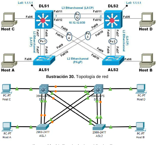
Una empresa de comunicaciones presenta una estructura Core acorde a la topología de red, en donde el estudiante será el administrador de la red, el cual deberá configurar e interconectar entre sí cada uno de los dispositivos que forman parte del escenario, acorde con los lineamientos establecidos para el direccionamiento IP, etherchannels, VLANs y demás aspectos que forman parte del escenario propuesto.
Topología de red
Ilustración 30. Topología de red
36
2.1. Parte 1: Configurar la red de acuerdo con las especificaciones.
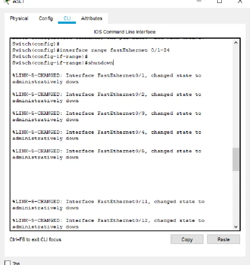
a. Apagar todas las interfaces en cada switch.
ASL1
Switch>enable Switch#config t
Enter configuration commands, one per line. End with CNTL/Z. Switch(config)#
Switch(config)#interface range fastEthernet 0/1-24 Switch(config-if-range)#
Switch(config-if-range)#shutdown
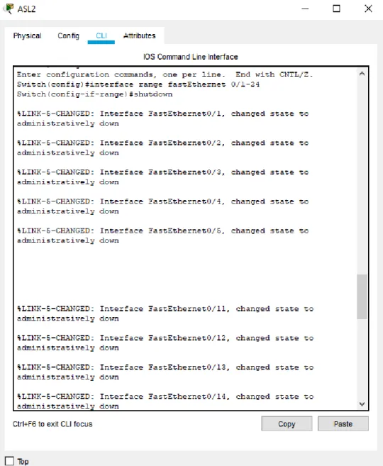
37 ASL2
Switch>enable Switch#config t
Enter configuration commands, one per line. End with CNTL/Z. Switch(config)#
Switch(config)#interface range fastEthernet 0/1-24 Switch(config-if-range)#
Switch(config-if-range)#shutdown
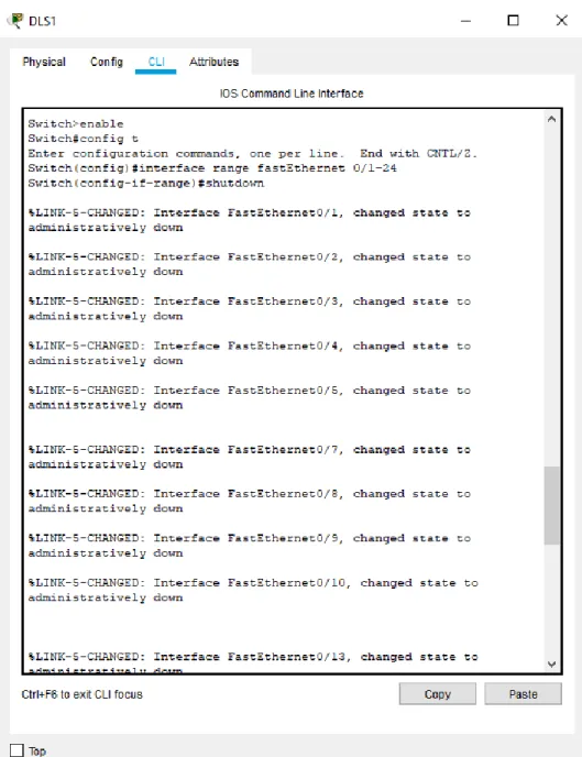
38 DSL1
Switch>enable Switch#config t
Enter configuration commands, one per line. End with CNTL/Z. Switch(config)#
Switch(config)#interface range fastEthernet 0/1-24 Switch(config-if-range)#
Switch(config-if-range)#shutdown
39 DSL2
Switch>enable Switch#config t
Enter configuration commands, one per line. End with CNTL/Z. Switch(config)#
Switch(config)#interface range fastEthernet 0/1-24 Switch(config-if-range)#
Switch(config-if-range)#shutdown
40
Evidencias de estar apagadas en cada switch: Switch>show ip interface brief
ASL1
Ilustración 36. Interface apagada ASL1 ASL2
41 DSL1
Ilustración 38. Interface apagada DSL1 DSL2
42
Ilustración 40. Todas las interfaces apagadas
b. Asignar un nombre a cada switch acorde al escenario establecido.
ASL1
Switch>enable
Switch#config terminal
Enter configuration commands, one per line. End with CNTL/Z. Switch(config)#hostname ASL1
ASL1(config)#exit ASL1#
%SYS-5-CONFIG_I: Configured from console by console
Ilustración 41. Asignación de nombre al Switch 1
ASL2
Switch>enable Switch#config t
43 ASL2(config)#exit
ASL2#
%SYS-5-CONFIG_I: Configured from console by console
Ilustración 42. Asignación de nombre al Switch 2
DSL1 Switch>
Switch>enable
Switch#config terminal
Enter configuration commands, one per line. End with CNTL/Z. Switch(config)#hostname DLS1
DLS1(config)#exit DLS1#
%SYS-5-CONFIG_I: Configured from console by console
Ilustración 43. Asignación de nombre al Switch 3
DSL2
Switch#enable
Switch#config terminal
Enter configuration commands, one per line. End with CNTL/Z. Switch(config)#hostname DSL2
DSL2(config)#exit DSL2#
44
Ilustración 44. Asignación de nombre al Switch 4
c. Configurar los puertos troncales y Port-channels tal como se muestra en el diagrama.
1) La conexión entre DLS1 y DLS2 será un EtherChannel capa-3 utilizando LACP. Para DLS1 se utilizará la dirección IP 10.12.12.1/30 y para DLS2 utilizará 10.12.12.2/30.
DLS1>enable
DLS1#config terminal
Enter configuration commands, one per line. End with CNTL/Z. DLS1(config)#int vlan 800
DLS1(config-if)#ip address 10.12.12.1 255.255.255.252 DLS1(config-if)#exit
DLS1(config)#int range f0/11-12 DLS1(config-if-range)#shutdown
DLS1(config-if-range)#channel-group 12 mode active DLS1(config-if-range)#
Creating a port-channel interface Port-channel 12 DLS1(config-if-range)#shutdown
DLS1(config-if-range)#
45 DSL2>
DSL2>enable
DSL2#config terminal
Enter configuration commands, one per line. End with CNTL/Z. DSL2(config)#int vlan 800
DSL2(config-if)#ip address 10.12.12.2 255.255.255.252 DSL2(config-if)#exit
DSL2(config)#int range f0/11-12 DSL2(config-if-range)#shutdown
DSL2(config-if-range)#channel-group 12 mode active DSL2(config-if-range)#
Creating a port-channel interface Port-channel 12 DSL2(config-if-range)#no shutdown
%LINK-5-CHANGED: Interface FastEthernet0/11, changed state to down %LINK-5-CHANGED: Interface FastEthernet0/12, changed state to down DSL2(config-if-range)#
46
Observación de los Etherchannel : show etherchannel summary
Ilustración 47. Mostrar EtherChannel DSL1
47
2) Los Port-channels en las interfaces Fa0/7 y Fa0/8 utilizarán LACP. DLS1#
DLS1#config term
Enter configuration commands, one per line. End with CNTL/Z. DLS1(config)#int range f0/7-8
DLS1(config-if-range)#shutdown
DLS1(config-if-range)#channel-group 1 mode active DLS1(config-if-range)#
Creating a port-channel interface Port-channel 1 DLS1(config-if-range)#no shutdown
%LINK-5-CHANGED: Interface FastEthernet0/7, changed state to down %LINK-5-CHANGED: Interface FastEthernet0/8, changed state to down DLS1(config-if-range)#
Ilustración 49. Port-channel utilizando LACP desde el DSL1
ASL1>enable ASL1#conf term
Enter configuration commands, one per line. End with CNTL/Z. ASL1(config)#int range f0/7-8
ASL1(config-if-range)#shutdown
ASL1(config-if-range)#channel-group 1 mode active ASL1(config-if-range)#
48
Ilustración 50. Port-channel utilizando LACP desde el ASL1
DSL2>enable
DSL2#config terminal
Enter configuration commands, one per line. End with CNTL/Z. DSL2(config)#int range f0/7-8
DSL2(config-if-range)#shutdown
DSL2(config-if-range)#channel-group 2 mode active DSL2(config-if-range)#
49
Ilustración 51. Port-channel utilizando LACP desde el DSL2
ALS2#conf term
ALS2(config)#int range f0/7-8 ALS2(config-if-range)#shutdown
ALS2(config-if-range)#channel-group 2 mode active ALS2(config-if-range)#no shutdown
50
Ilustración 53. Port-channels en las interfaces Fa0/7 y Fa0/8 utilizan LACP
3) Los Port-channels en las interfaces F0/9 y fa0/10 utilizará PAgP.
DLS1>enable
DLS1#config terminal
Enter configuration commands, one per line. End with CNTL/Z. DLS1(config)#int range f0/9-10
DLS1(config-if-range)#shutdown
DLS1(config-if-range)#channel-group 4 mode desirable DLS1(config-if-range)#
51 ASL1>enable
ASL1#conf terminal
Enter configuration commands, one per line. End with CNTL/Z. ASL1(config)#int range f0/9-10
ASL1(config-if-range)#shutdown
ASL1(config-if-range)#channel-group 4 mode desirable ASL1(config-if-range)#
Creating a port-channel interface Port-channel 4 ASL1(config-if-range)#no shutdown
Ilustración 55. Port-channel utilizando PAgP desde el ASL1
DSL2>enable
DSL2#config terminal
Enter configuration commands, one per line. End with CNTL/Z. DSL2(config)#int range f0/9-10
DSL2(config-if-range)#shutdown
DSL2(config-if-range)#channel-group 3 mode desirable DSL2(config-if-range)#
52
Ilustración 56. Port-channel utilizando PAgP desde el DSL2
ALS2#conf term
ALS2(config)#int range f0/9-10 ALS2(config-if-range)#shutdown
53
Ilustración 57. Port-channel utilizando PAgP desde el ASL2
54
4) Todos los puertos troncales serán asignados a la VLAN 800 como la VLAN nativa.
DLS1#conf term
Enter configuration commands, one per line. End with CNTL/Z. DLS1(config)#int range f0/7-12
DLS1(config-if-range)#switchport trunk native vlan 800 DLS1(config-if-range)#switchport mode trunk
DLS1(config-if-range)#switchport nonegotiate DLS1(config-if-range)#no shutdown
DLS1(config-if-range)#exit DLS1(config)#
55 DLS2#conf term
Enter configuration commands, one per line. End with CNTL/Z. DLS2(config)#int range f0/7-12
DLS2(config-if-range)#switchport trunk native vlan 800 DLS2(config-if-range)#switchport mode trunk
DLS2(config-if-range)#switchport nonegotiate DLS2(config-if-range)#no shutdown
DLS2(config-if-range)#exit DLS2(config)#
Ilustración 60. Configuración de puertos troncales en DSL2
ASL1#conf term
Enter configuration commands, one per line. End with CNTL/Z. ASL1(config)#int range f0/7-12
ASL1(config-if-range)#switchport trunk native vlan 800 ASL1(config-if-range)#switchport mode trunk
56 ASL1(config-if-range)#no shutdown ASL1(config-if-range)#exit
ASL1(config)#
Ilustración 61. Configuración de puertos troncales en ASL1
ALS2#conf term
Enter configuration commands, one per line. End with CNTL/Z. ASL2(config)#int range f0/7-12
ASL2(config-if-range)#switchport trunk native vlan 800 ASL2(config-if-range)#switchport mode trunk
ASL2(config-if-range)#switchport nonegotiate ASL2(config-if-range)#no shutdown
57
Ilustración 62. Configuración de puertos troncales en ASL2
58
d. Configurar DLS1, ALS1, y ALS2 para utilizar VTP versión 3 1) Utilizar el nombre de dominio UNAD con la contraseña cisco123 DLS1(config)#vtp domain UNAD
Domain name already set to UNAD. DLS1(config)#vtp pass cisco123
Setting device VLAN database password to cisco123 DLS1(config)#vtp version 3
“Solo es funcional con vtp versión 2”
Ilustración 64. Configuración DSL1 para utilizar VTP
“Solo es funcional con vtp versión 2”
ASL1(config)#vtp domain UNAD Domain name already set to UNAD. ASL1(config)#vtp pass cisco123
Setting device VLAN database password to cisco123 ASL1(config)#vtp version 3
59 “Solo es funcional con vtp versión 2”
ASL2(config)#vtp domain UNAD
Changing VTP domain name from NULL to UNAD ASL2(config)#vtp pass cisco123
Setting device VLAN database password to cisco123 ASL2(config)#vtp version 3
Ilustración 66. Configuración ASL2 para utilizar VTP
2) Configurar DLS1 como servidor principal para las VLAN. DLS1(config)#vtp mode server
Device mode already VTP SERVER.
Ilustración 67. Configuración DSL1 como servidor
3) Configurar ALS1 y ALS2 como clientes VTP. ASL1(config)#vtp mode client
Setting device to VTP CLIENT mode.
60 ALS1#show vtp status
Ilustración 69. Visualizar ASL1 como cliente VTP
ASL2(config)#vtp mode client
ASL2#show vtp status
61
e. Configurar en el servidor principal las siguientes VLAN:
Tabla 1. Visualización del número y nombre de las VLANS
Para el correcto funcionamiento de la configuración se elimina la cuarta cifra de cada número asignado como se indica en la tabla:
Número de VLAN Nombre de VLAN Número de VLAN
Nombre de VLAN
800 NATIVA 434 ESTACIONAMIENTO
12 EJECUTIVOS 123 MANTENIMIENTO
234 HUESPEDES 101 VOZ
111 VIDEONET 345 ADMINISTRACIÓN
Tabla 2. Visualización del número y nombre de las VLANS
62
Ilustración 71. Configuración del número y nombre de las VLANS
SHOW VLAN
63 f. En DLS1, suspender la VLAN 434. No Permite suspender las VLAN DLS1(config)#vlan 434
DLS1(config-vlan)# state suspend
Ilustración 73. suspender la VLAN 434
g. Configurar DLS2 en modo VTP transparente VTP utilizando VTP versión 2, y configurar en DLS2 las mismas VLAN que en DLS1.
DSL2>enable
DSL2#config terminal
Enter configuration commands, one per line. End with CNTL/Z. DSL2(config)#vtp domain UNAD
Changing VTP domain name from NULL to UNAD DSL2(config)#vtp version 2
DSL2(config)#vtp mode transparent
64
Ilustración 74. Configuración de las VLAN en DSL2
h. Suspender VLAN 434 en DLS2. DLS2(config)#vlan 434
DLS2(config-vlan)# state suspend DLS2(config)#
No hay la posibilidad de suspender este esta VLAN debido a que packet tracer no lo permite
Ilustración 75. Suspender VLAN 434 en DLS2
65 DLS2#configure terminal
DLS2(config)#vlan 567
DLS2(config-vlan)#name CONTABILIDAD
Ilustración 76. VLAN con el nombre CONTABILIDAD.
En 2 port-channel truncales se limita la vlan 567:
DLS2(config)#interface port-channel 2
DLS2(config-if)#switchport trunk allowed vlan except 567 DLS2(config)#interface port-channel 3
DLS2(config-if)#switchport trunk allowed vlan except 567
Ilustración 77 Limitación de los puertos truncales en las vlan 67
j. Configurar DLS1 como Spanning tree root para las VLAN 1, 12, 434, 800, 1010, 1111 y 3456 y como raíz secundaria para las VLAN 123 y 234.
El cambio inicial de las VLAN fueron : 1,12,434,800,101,111,345
123,234
DLS1(config)#spanning-tree vlan 1,12,434,800,101,111,345 root primary
DLS1(config)#spanning-tree vlan 123,234 root secondary
66
k. Configurar DLS2 como Spanning tree root para las VLAN 123 y 234 y como una raíz secundaria para las VLAN 12, 434, 800, 1010, 1111 y 3456.
El cambio inicial de las VLAN fueron : 123,234
1,12,434,800,101,111,345
DLS2(config)#spanning-tree vlan 123,234 root primary
DLS2(config)#spanning-tree vlan 1,12,434,800,101,111,345 root secondary
Ilustración 79. Configuración Spanning tree root en DSL2
l. Configurar todos los puertos como troncales de tal forma que solamente las VLAN que se han creado se les permitirá circular a través de éstos puertos. DLS1(config)#int range f0/7-12
DLS1(config-if-range)#switchport mode trunk
DLS1(config-if-range)#switchport trunk native vlan 800 DLS1(config-if-range)#switchport trunk native vlan 12 DLS1(config-if-range)#switchport trunk native vlan 234 DLS1(config-if-range)#switchport trunk native vlan 111 DLS1(config-if-range)#switchport trunk native vlan 434 DLS1(config-if-range)#switchport trunk native vlan 123 DLS1(config-if-range)#switchport trunk native vlan 101 DLS1(config-if-range)#switchport trunk native vlan 345 DLS1(config-if-range)#switchport trunk native vlan 345 DLS1(config-if-range)#switchport nonegotiate
67 DSL2(config)#int range f0/7-12
DSL2(config-if-range)#switchport mode trunk
DSL2(config-if-range)#switchport trunk native vlan 800 DSL2(config-if-range)#switchport trunk native vlan 12 DSL2(config-if-range)#switchport trunk native vlan 234 DSL2(config-if-range)#switchport trunk native vlan 111 DSL2(config-if-range)#switchport trunk native vlan 434 DSL2(config-if-range)#switchport trunk native vlan 123 DSL2(config-if-range)#switchport trunk native vlan 101 DSL2(config-if-range)#switchport trunk native vlan 345 DSL2(config-if-range)#switchport trunk native vlan 345 DSL2(config-if-range)#switchport nonegotiate
Ilustración 81. Configuración de troncales en DSL2
ASL1(config)#int range f0/7-12
ASL1(config-if-range)#switchport mode trunk
ASL1(config-if-range)#switchport trunk native vlan 800 ASL1(config-if-range)#switchport trunk native vlan 12 ASL1(config-if-range)#switchport trunk native vlan 234 ASL1(config-if-range)#switchport trunk native vlan 111 ASL1(config-if-range)#switchport trunk native vlan 434 ASL1(config-if-range)#switchport trunk native vlan 123 ASL1(config-if-range)#switchport trunk native vlan 101 ASL1(config-if-range)#switchport trunk native vlan 345 ASL1(config-if-range)#switchport trunk native vlan 345 ASL1(config-if-range)#switchport nonegotiate
68
Ilustración 82. Configuración de troncales en ASL1
ASL2>enable ASL2#config t
Enter configuration commands, one per line. End with CNTL/Z. ASL2(config)#
ASL2(config)#int range f0/7-12
ASL2(config-if-range)#switchport mode trunk
ASL2(config-if-range)#switchport trunk native vlan 800 ASL2(config-if-range)#switchport trunk native vlan 12 ASL2(config-if-range)#switchport trunk native vlan 234 ASL2(config-if-range)#switchport trunk native vlan 111 ASL2(config-if-range)#switchport trunk native vlan 434 ASL2(config-if-range)#switchport trunk native vlan 123 ASL2(config-if-range)#switchport trunk native vlan 101 ASL2(config-if-range)#switchport trunk native vlan 345 ASL2(config-if-range)#switchport trunk native vlan 345 ASL2(config-if-range)#switchport nonegotiate
69
Ilustración 83. Configuración de troncales en ASL2
m. Configurar las siguientes interfaces como puertos de acceso, asignados a las VLAN de la siguiente manera:
Tabla 3. Visualización de las interfaces asignadas a las VLAN
Se suprime la cuarta cifra de algunos números debido a que Packet Tracer no permite números tan altos.
Interfaz DLS1 DLS2 ASL1 ASL2
Interfaz Fa0/6 345 12 , 101 123 , 101 234
Interfaz Fa0/15 111 111 111 111
Interfaz F0/16-18 567
Tabla 4. Visualización de las nuevas interfaces asignadas a las VLAN
DLS1(config)#interface f0/6
DLS1(config-if)#switchport access vlan 345 DLS1(config-if)#no shutdown
DLS1(config-if)#exit
DLS1(config)#interface f0/15
70 DLS1(config-if)#no shutdown
DLS1(config-if)#exit
Ilustración 84. Configuración de la interface en DSL1
DLS2(config)#interface F0/6
DLS2(config-if)#switchport access vlan 12 DLS2(config-if)#switchport access vlan 101 DLS2(config-if)#no shutdown
DLS2(config-if)#interface F0/15
DLS2(config-if)#switchport access vlan 111 DLS2(config-if)#no shutdown
DLS2(config-if)#exit
DLS2(config)#int range f0/16-18
DLS2(config-if-range)#switchport access vlan 567 DLS2(config-if-range)#no shutdown
DLS2(config-if-range)#exit DLS2(config)#
Ilustración 85. Configuración de la interface en DSL2
ASL1(config)#int f0/6
ASL1(config-if)#switchport access vlan 123 ASL1(config-if)#switchport access vlan 101 ASL1(config-if)#no shutdown
71 ASL1(config)#int f0/15
ASL1(config-if)#switchport access vlan 111 ASL1(config-if)#no shutdown
ASL1(config-if)#exit ASL1(config)#
Ilustración 86. Configuración de la interface en ASL1
ASL2(config)#int f0/6
ASL2(config-if)#switchport access vlan 234 ASL2(config-if)#no shutdown
ASL2(config-if)#exit ASL2(config)#int f0/15
ASL2(config-if)#switchport access vlan 111 ASL2(config-if)#no shutdown
ASL2(config-if)#exit ASL2(config)#
72
2.2. Parte 2: conectividad de red de prueba y las opciones configuradas.
a. Verificar la existencia de las VLAN correctas en todos los switches y la asignación de puertos troncales y de acceso
Verificar VLAN DSL1$ show vlan
Ilustración 88. Mostrar VLAN en DSL1
73
74
Ilustración 90. Mostrar VLAN en ASL1
ASL2$ show vlan
75 Puertos troncales y de acceso DSL1$ show interface trunk DSL2$ show interface trunk ASL1$ show interface trunk
Ilustración 92. Mostrar interface troncal en DSL1
ASL2$ show interface trunk
76
b. Verificar que el EtherChannel entre DLS1 y ALS1 está configurado correctamente
DSL1# show etherchannel
Ilustración 94. Verificación del EtherChannel en DLS1
ASL1# show etherchannel
Ilustración 95. Verificación del EtherChannel en ASL1
77 DSL1# show spanning-tree
Ilustración 96. Verificación del Spanning tree en DSL1
78
Ilustración 97. Verificación del Spanning tree en DSL2
FINALIZADO
79
CONCLUSIONES
Con la utilización del software packet tracer se desarrolla un montaje práctico que permite establecer el hardware necesario para la implementación de una red de datos al interior de una empresa y a distintas ciudades.
La implementación de protocolos como OSPF y EIGRP permitió el correcto transporte de datos a través de las líneas de redes.
OSPF es un protocolo de routing de estado de enlace que se utilizó en un diseño de modo escalable, definiendo routers en distintas áreas admitiendo un sistema jerárquico, además de ser seguro autenticando la configuración MD5.
EIGRP utilizó el ancho de banda de los enlaces garantizando un transporte de datos eficaz y mejorando las propiedades de convergencia.
La posibilidad de utilizar y mezclar los protocolos de direccionamiento de red como el ipv4 e ipv6 que son los encargados de dirigir y encaminar los paquetes de red posibilitando configurar ajustes básicos y complejos.
Con la configuración de esta red se da énfasis en la seguridad y en la profundización de direcciones entre routers.
80
BIBLIOGRAFÍA
Teare, D., Vachon B., Graziani, R. (2015). CISCO Press (Ed). Basic Network and Routing Concepts. Implementing Cisco IP Routing (ROUTE) Foundation Learning Guide CCNP ROUTE 300-101. Recuperado de
https://1drv.ms/b/s!AmIJYei-NT1IlnMfy2rhPZHwEoWx
Teare, D., Vachon B., Graziani, R. (2015). CISCO Press (Ed). EIGRP Implementation. Implementing Cisco IP Routing (ROUTE) Foundation Learning Guide CCNP ROUTE 300-101. Recuperado de
https://1drv.ms/b/s!AmIJYei-NT1IlnMfy2rhPZHwEoWx
Froom, R., Frahim, E. (2015). CISCO Press (Ed). Spanning Tree Implementation. Implementing Cisco IP Switched Networks (SWITCH) Foundation Learning Guide CCNP SWITCH 300-115. Recuperado de
https://1drv.ms/b/s!AmIJYei-NT1IlnWR0hoMxgBNv1CJ