EVALUACIÓN – PRUEBA DE HABILIDADES PRÁCTICAS CCNA
DIPLOMADO DE PROFUNDIZACIÓN CISCO (DISEÑO E IMPLEMENTACIÓN DE SOLUCIONES INTEGRADAS LAN / WAN)
CARLOS ALBERTO SAYEH TANG
UNIVERSIDAD NACIONAL ABIERTA A DISTANCIA – UNAD PROGRAMA DE INGENIERÍA DE SISTEMAS
DIPLOMADO DE PROFUNDIZACIÓN CISCO (DISEÑO E IMPLEMENTACIÓN DE SOLUCIONES INTEGRADAS LAN/WAN)
EVALUACIÓN – PRUEBA DE HABILIDADES PRÁCTICAS CCNA
DIPLOMADO DE PROFUNDIZACIÓN CISCO (DISEÑO E IMPLEMENTACIÓN DE SOLUCIONES INTEGRADAS LAN / WAN)
CARLOS ALBERTO SAYEH TANG
Trabajo de Diplomado para optar por el título de Ingeniero de Sistemas
Ingeniero Juan Carlos Vesga
UNIVERSIDAD NACIONAL ABIERTA A DISTANCIA – UNAD PROGRAMA DE INGENIERÍA DE SISTEMAS
DIPLOMADO DE PROFUNDIZACIÓN CISCO (DISEÑO E IMPLEMENTACIÓN DE SOLUCIONES INTEGRADAS LAN/WAN)
Corozal, 11 de Enero de 2019
NOTA DE ACEPTACIÓN
Presidente del Jurado
Jurado
DEDICATORIA
Agradezco primero que todo a Dios Todopoderoso dueño de la Sabiduría y el Conocimiento, quien me permitió culminar éste Diplomado y haber adquirido este nuevo conocimiento para mí.
AGRADECIMIENTOS
TABLA DE CONTENIDO
GLOSARIO……….10
RESUMEN……….11
ABSTRACT………12
INTRODUCCIÓN………..13
ESCENARIO 1………..14
Situación Escenario 1………..17
Descripción de equipos necesarios………...17
Archivos de Configuración Escenario 1………...28
ESCENARIO 2………..………..………..35
Situación Escenario 2………..………..………..35
Descripción de equipos necesarios………...36
CONCLUSIONES……….66
LISTA DE TABLAS
LISTA DE FIGURAS
Imagen 1. Configuración de IP, usando protocolo DHCP ………..20
Imagen 2. Ping de PC21 a 192.168.21.3 ………..21
Imagen 3. Ping de Laptop0 a 192.168.20.2 ....……….22
Imagen 4. Asignación de IPv6……….…….…..22
Imagen 5. Ping desde Laptop31 al Servidor0………...23
Imagen 6. Activación de Protocolo DHCP para la Laptop31……….….23
Imagen 7. Ping desde R2 al ISP..………...25
Imagen 8. Ping desde R3 a Pc21………...25
Imagen 9. Ping desde Laptop20 a ISP...……… ...……26
Imagen 10. Ping desde R3 al Servidor….……… ...……… ....26
Imagen 11. Ping desde R1 a R3 ……… …...26
Imagen 12. Ruta desde Laptop 21 a ISP………...27
Imagen 13. Ping entre PC30 y Laptop 31………..27
Imagen 14. Escenario 2……….………...37
Imagen 15. Comando Show ip route en R1…...………...40
Imagen 16. Comando Show ip ospf en R1….………...40
Imagen 17. Comando Show ip ospf interface s0/0/0 en R1. ..……… …..41
Imagen 18. Comando Show ip protocols R1……….41
Imagen 19. Comando Show ip route en R2…………...………...41
Imagen 20. Comando Show ip ospf en R2……… ...42
Imagen 21. Comando Show ip ospf interface s0/0/0....………...42
Imagen 22. Comando Show ip protocols ……… ….42
Imagen 23. Comando Show ip route ……..…………...………… ...……… …..43
Imagen 24. Comando Show ip osp .……… ...…...……… …..43
Imagen 25. Comando Show ip ospf interface s0/0/1....………...43
Imagen 26. Comando Show ip protocols ………. ……44
Imagen 27. Comando Show ip route a R1..…………...………...48
Imagen 29. Ping de R2 a R1...………….….…………...………...51
Imagen 30. Ping de R2 a R3...……….…………...……….………...51
Imagen 31. Ping de R3 a R1....……….…………...………...51
Imagen 32. Ping de R3 a R2....……….…………...………...52
GLOSARIO
CONFIGURAR: Adaptar una aplicación software o un elemento hardware al resto de los elementos del entorno y a las necesidades específicas del usuario. Es una tarea esencial antes de trabajar con cualquier nuevo elemento.
DOMINIO: Parte de una dirección de Internet que identifica un sitio web y que describe el tipo de empresa u organización a la que pertenece o bien el país donde está registrado.
ENCAPSULAMIENTO: Es un método de diseño modular de protocolos de comunicación en el cual las funciones lógicas de una red son abstraídas ocultando información a las capas de nivel superior
GATEWAY: (Puerta de enlace) Un Gateway es un dispositivo que permite interconectar redes con protocolos y arquitecturas diferentes a todos los niveles de comunicación. Su propósito es traducir la información del protocolo utilizado en una red al protocolo usado en la red de destino.
INTERFAZ: Es un término que procede del vocablo inglés interface. En informática, esta noción sirve para señalar a la conexión que se da de manera física y a nivel de utilidad entre dispositivos o sistemas.
PROTOCOLO: Un protocolo de red designa el conjunto de reglas que rigen el intercambio de información a través de una red de computadoras.
ROUTER: Un router es un dispositivo de hardware que permite la interconexión de ordenadores en red.
SERVIDOR: Es un equipo informático que forma parte de una red y provee servicios a otros equipos cliente. Se denomina servidor dedicado, aquel que dedica todos sus recursos a atender solicitudes de los equipos cliente.
SWITCH: Un Switch o conmutador es un dispositivo de interconexión de redes informáticas. En computación y en informática de redes, un Switch es el dispositivo analógico que permite interconectar redes.
TOPOLOGÍA: En Informática se define como el mapa físico o lógico de una red para intercambiar datos. En otras palabras, es la forma en que está diseñada la red, sea en el plano físico o lógico.
RESUMEN
Antes de diseñar y crear una red se debe pensar que mediante la creación de ésta se le va a dar solución a un problema de comunicación entre dispositivos, llámense computadoras, celulares, impresoras, portátiles, etc. Dicha red necesita de medios de conexión, y para eso hay otros dispositivos que ayudan con esa conexión, entre esos encontramos los Routers, Switchs, entre otros. Dichos dispositivos deben ser configurados apropiadamente y dependiendo de las necesidades de cada red, ya que cada una es diferente de las otras.
El objetivo de realizar este trabajo en cada escenario es demostrar la habilidades prácticas adquiridas durante el diplomado de profundización CCNA I y CCNA II, en el Escenario 1 se demuestra y se refuerza la capacidad de implementar NAT, servidor de DHCP, RIPV2 y además el routing entre VLAN. Los cuales son factores muy importantes en al momento de diseñar redes que necesiten este tipo de configuraciones para facilitar su conexión.
Por otra parte el Escenario 2 es una empresa de Tecnología que posee tres sucursales distribuidas en las ciudades de Bogotá, Miami y Buenos Aires, donde se debe configurar e interconectar entre sí cada uno de los dispositivos de red. Se implementó la configuración de protocolos de enrutamiento dinámico OSPF V2 para interconectar los Routers. En el router de Miami se realizó la configuración o parametrización del router Inter-VLan, DHCP para la VLan de Administración y Mercadeo, listas de acceso para controlar el tráfico desde R1 hacia R2.
ABSTRACT
Before designing and creating a network, you should think that by creating it you will be able to solve a communication problem between devices, call computers, cell phones, printers, laptops, etc., said network needs connection means, and for that there are other devices that help with that connection, among which we find the Routers, Switchs, among others. These devices must be configured appropriately and depending on the needs of each network, since each one is different from the others.
The objective of carrying out this work in each scenario is to demonstrate the practical skills acquired during the CCNA I and CCNA II deepening course, in Scenario 1 the ability to implement NAT, DHCP server, RIPV2 and in addition the routing is demonstrated and reinforced. between VLANs Which are very important factors when designing networks that need this type of configuration to facilitate their connection.
On the other hand, Scenario 2 is a Technology company that has three branches distributed in the cities of Bogotá, Miami and Buenos Aires, where each of the network devices must be configured and interconnected.
INTRODUCCIÓN
En el presente trabajo se pondrán en práctica las habilidades adquiridas durante los cursos de CCNA 1 y CCNA 2, mediante el desarrollo de dos ejercidos, en donde se plantean dos casos que debemos resolver como administradores de las respectivas redes, mediante el uso de la aplicación Packet Tracer.
Cada ejercicio es una situación diferente en los cuales se pondrán en práctica los conocimientos acerca de enrutamiento mediante el uso de algunos dispositivos como el Router y el Switch, además de niveles de seguridad e implementación de varios tipos de configuraciones y servicios tales como NAT, DHCP, OSPFv2, Enlaces Troncales, entre otros.
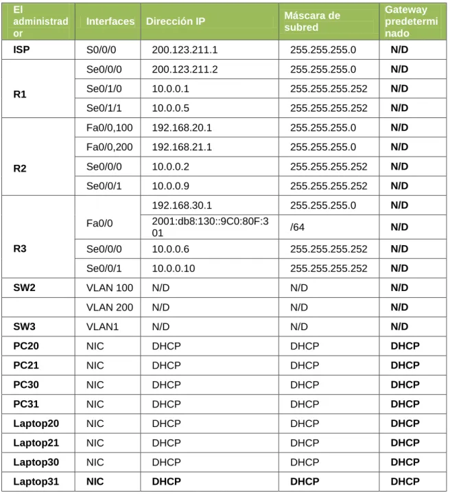
Tabla 1. Direccionamiento Escenario 1.
El
administrad or
Interfaces Dirección IP Máscara de subred
Gateway predetermi nado ISP S0/0/0 200.123.211.1 255.255.255.0 N/D
R1
Se0/0/0 200.123.211.2 255.255.255.0 N/D Se0/1/0 10.0.0.1 255.255.255.252 N/D Se0/1/1 10.0.0.5 255.255.255.252 N/D
R2
Fa0/0,100 192.168.20.1 255.255.255.0 N/D Fa0/0,200 192.168.21.1 255.255.255.0 N/D Se0/0/0 10.0.0.2 255.255.255.252 N/D Se0/0/1 10.0.0.9 255.255.255.252 N/D
R3
Fa0/0
192.168.30.1 255.255.255.0 N/D 2001:db8:130::9C0:80F:3
01 /64 N/D
Se0/0/0 10.0.0.6 255.255.255.252 N/D Se0/0/1 10.0.0.10 255.255.255.252 N/D
SW2 VLAN 100 N/D N/D N/D
VLAN 200 N/D N/D N/D
SW3 VLAN1 N/D N/D N/D
PC20 NIC DHCP DHCP DHCP
PC21 NIC DHCP DHCP DHCP
PC30 NIC DHCP DHCP DHCP
PC31 NIC DHCP DHCP DHCP
Laptop20 NIC DHCP DHCP DHCP
Laptop21 NIC DHCP DHCP DHCP
Laptop30 NIC DHCP DHCP DHCP
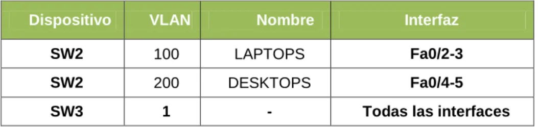
Tabla 2. Asignación de VLAN y de puertos
Dispositivo VLAN Nombre Interfaz
SW2 100 LAPTOPS Fa0/2-3
SW2 200 DESKTOPS Fa0/4-5
SW3 1 - Todas las interfaces
Tabla 3. Enlaces troncales
Dispositivo local
Interfaz local Dispositivo remoto
Situación Escenario 1
En esta actividad, demostrará y reforzará su capacidad para implementar NAT, servidor de DHCP, RIPV2 y el routing entre VLAN, incluida la configuración de direcciones IP, las VLAN, los enlaces troncales y las subinterfaces. Todas las pruebas de alcance deben realizarse a través de ping únicamente.
Descripción de los equipos necesarios: De acuerdo a la topología necesitaremos
4 Routers 1841 2 Switch 2950-24 4 PC’s de Escritorio 4 Portátiles
1 Servidor Genérico
Se le debe agregar a cada Router 1 tarjeta con puertos seriales para la interconexión entre ellos junto con sus respectivos cables (el Router 1 necesitará 2 tarjeta o 4 puertos).
Las demás conexiones se hacen con cable de red estándar
Descripción de las actividades
SW2 VLAN y las asignaciones de puertos de VLAN deben cumplir con la tabla 1. Switch>enable
Switch#conf t
Enter configuration commands, one per line. End with CNTL/Z. Switch(config)#hostname SW2
SW2(config)#vlan 100
SW2(config-vlan)#name LAPTOPS SW2(config-vlan)#vlan 200
SW2(config-vlan)#name DESKTOPS SW2(config-vlan)#int range fa0/2-3
SW2(config-if-range)#switchport mode access SW2(config-if-range)#switchport access vlan 100 SW2(config-if-range)#int range f0/4-5
SW2(config-if-range)#switchport mode access SW2(config-if-range)#switchport access vlan 200 SW2(config-if-range)#int fa0/1
SW2(config-if)#switchport mode trunk
Los puertos de red que no se utilizan se deben deshabilitar. SW2(config-if)#int range fa0/6-24
Switch>en Switch#conf t
Switch(config)#hostname SW3 SW3(config)#int range f0/7-24 SW3(config-if-range)#shutdown
La información de dirección IP R1, R2 y R3 debe cumplir con la tabla 1.
Configuración del Router 1
Router>en Router#conf t
Enter configuration commands, one per line. End with CNTL/Z. Router(config)#hostname R1
R1(config)#int s0/0/0
R1(config-if)#ip address 200.123.211.2 255.255.255.0 R1(config-if)#no shut
R1(config-if)#int s0/1/0
R1(config-if)#ip address 10.0.0.1 255.255.255.252 R1(config-if)#no shut
R1(config-if)#int s0/1/1
R1(config-if)#ip address 10.0.0.5 255.255.255.252 R1(config-if)#no shut
Configuración del Router 2
Router>en Router#conf t
Enter configuration commands, one per line. End with CNTL/Z. Router(config)#hostname R2
R2(config)#int f0/0.100
R2(config-subif)#encapsulation dot1Q 100
R2(config-subif)#ip address 192.168.20.1 255.255.255.0 R2(config-subif)#int f0/0.200
R2(config-subif)#encapsulation dot1Q 200 R2(config-subif)#ip add
R2(config-subif)#ip address 192.168.21.1 255.255.255.0 R2(config-subif)#int f0/0
R2(config-if)#ip address 10.0.0.2 255.255.255.252 R2(config-if)#no shut
R2(config-if)#int s0/0/1 R2(config-if)#ip add
R2(config-if)#ip address 10.0.0.9 255.255.255.252 R2(config-if)#no shut
Configuración del Router 3
Router>en Router#conf t
Enter configuration commands, one per line. End with CNTL/Z. Router(config)#hostname R3
R3(config)#ipv6
R3(config)#ipv6 unicast-routing R3(config)#int f0/0
R3(config-if)#ip address 192.168.30.1 255.255.255.0 R3(config-if)#ipv6 address 2001:db8:130::9C0:80F:301/64 R3(config-if)#ipv6 dhcp server vlan_1
R3(config-if)#ipv6 nd other-config-flag R3(config-if)#no shutdown
R3(config-if)#int s0/0/0
R3(config-if)#ip address 10.0.0.6 255.255.255.252 R3(config-if)#no shutdown
R3(config-if)#int s0/0/1
R3(config-if)#ip address 10.0.0.10 255.255.255.252 R3(config-if)#no shutdown
Configuración del ISP
Router>en Router#conf t
Enter configuration commands, one per line. End with CNTL/Z. Router(config)#int s0/0/0
Router(config-if)#ip address 200.123.211.1 255.255.255.0 Router(config-if)#no shutdown
Imagen 1. Configuración de IP, usando protocolo DHCP
Todos los terminales los configuramos de esta manera, para que tomen la dirección del servidor DHCP.
R1 debe realizar una NAT con sobrecarga sobre una dirección Ipv4 pública. Asegúrese de que todos los terminales pueden comunicarse con Internet pública (haga ping a la dirección ISP) y la lista de acceso estándar se llama INSIDE-DEVS.
R1>en R1#conf t
Enter configuration commands, one per line. End with CNTL/Z.
R1(config)#ip nat pool INSIDE-DEVS 200.123.211.2 200.123.211.128 netmask 255.255.255.0
R1(config)#access-list 1 permit 192.168.0.0 0.0.255.255 R1(config)#access-list 1 permit 10.0.0.0 0.0.0.255 R1(config)#ip nat inside source list 1 int s0/0/0 overload R1(config)#int s0/1/0
R1(config-if)#ip nat inside R1(config-if)#int s0/1/1 R1(config-if)#ip nat inside R1(config-if)#int s0/0/0 R1(config-if)#ip nat out R1(config-if)#ip nat outside
R1 debe tener una ruta estática predeterminada al ISP que se configuró y que incluye esa ruta en el dominio RIPv2.
R1(config)#router rip
R1(config-router)#version 2
R1(config-router)#ip route 0.0.0.0 0.0.0.0 s0/0/0
FastEthernet0/0. R2>en
R2#conf t
Enter configuration commands, one per line. End with CNTL/Z. R2(config)#ip dhcp pool vlan_100
R2(dhcp-config)#network 192.168.20.1 255.255.255.0 R2(dhcp-config)#default-router 192.168.20.1
R2(dhcp-config)#ip dhcp pool vlan_200
R2(dhcp-config)#network 192.168.21.1 255.255.255.0 R2(dhcp-config)#default-router 192.168.21.1
R2 debe, además de enrutamiento a otras partes de la red, ruta entre las VLAN 100 y 200.
Con la configuración hecha las VLAN tienen acceso entre sí, como consta en el siguiente PING.
Imagen 3. Ping de Laptop0 a 192.168.20.2
El Servidor0 es sólo un servidor Ipv6 y solo debe ser accesible para los dispositivos en R3 (ping).
Imagen 4. Asignación de IPv6
Imagen 5. Ping desde Laptop31 al Servidor0
La NIC instalado en direcciones Ipv4 e Ipv6 de Laptop30, de Laptop31, de PC30 y obligación de configurados PC31 simultáneas (dual-stack). Las direcciones se deben configurar mediante DHCP y DHCPv6.
Imagen 6. Activación de Protocolo DHCP para la Laptop31
La interfaz FastEthernet 0/0 del R3 también debe tener direcciones Ipv4 e Ipv6 configuradas (dual- stack).
R3#conf t
Enter configuration commands, one per line. End with CNTL/Z. Router(config)#ipv6
Router(config)#ipv6 unicast-routing Router(config)#int f0/0
Router(config-if)#ip address 192.168.30.1 255.255.255.0 Router(config-if)#ipv6 address 2001:db8:130::9C0:80F:301/64 Router(config-if)#ipv6 dhcp server vlan_1
Router(config-if)#ipv6 nd other-config-flag R3(config)#ip dhcp pool vlan_1
R3(dhcp-config)#network 192.168.30.1 255.255.255.0 R3(dhcp-config)#default-router 192.168.30.1
R3(dhcp-config)#ipv6 dhcp pool vlan_1 R3(config-dhcp)#dns-server 2001:db8:130::
R1, R2 y R3 intercambian información de routing mediante RIP versión 2.
Configuración de R1
R1(config)#router rip
R1(config-router)#version 2
Configuración de R2
R2(config)#router rip
R2(config-router)#version 2
Configuración de R2
R3(config)#router rip
R3(config-router)#version 2
R1, R2 y R3 deben saber sobre las rutas de cada uno y la ruta predeterminada desde R1.
Configuración de R1
R1(config-router)#network 10.0.0.4 R1(config-router)#network 10.0.0.0
R1(config-router)#default-information originate
Configuración de R2
R2(config-router)#network 192.168.20.0 R2(config-router)#network 192.168.21.0 R2(config-router)#network 10.0.0.0 R2(config-router)#network 10.0.0.8
Configuración de R3
R3(config-router)#network 192.168.0.0 R3(config-router)#network 10.0.0.8 R3(config-router)#network 10.0.0.4 R3(config-router)#exit
Verifique la conectividad. Todos los terminales deben poder hacer ping entre sí y a la dirección IP del ISP. Los terminales bajo el R3 deberían poder hacer Ipv6-ping entre ellos y el servidor.
Imagen 7. Ping desde R2 al ISP
Imagen 9. Ping desde Laptop20 a ISP
Imagen 10. Ping desde R3 al Servidor
Imagen 12. Ruta desde Laptop 21 a ISP
ARCHIVOS DE CONFIGURACIÓN ESCENARIO 1
R1
R1#show running-config Building configuration…
Current configuration : 1478 bytes !
version 12.4
no service timestamps log datetime msec no service timestamps debug datetime msec no service password-encryption
!
hostname R1 !
! !
enable secret 5 $1$mERr$9cTjUIEqNGurQiFU.ZeCi1 enable password cisco
! !
no ip cef no ipv6 cef !
!
no ip domain-lookup !
!
spanning-tree mode pvst !
!
interface FastEthernet0/0 no ip address
duplex auto speed auto shutdown !
interface FastEthernet0/1 no ip address
duplex auto speed auto shutdown !
ip address 200.123.211.2 255.255.255.0 ip nat outside
clock rate 2000000 !
interface Serial0/0/1 no ip address
clock rate 2000000 shutdown
!
interface Serial0/1/0
ip address 10.0.0.1 255.255.255.252 ip nat inside
clock rate 2000000 !
interface Serial0/1/1
ip address 10.0.0.5 255.255.255.252 ip nat inside
clock rate 2000000 !
interface Vlan1 no ip address shutdown ! router rip version 2 network 10.0.0.0 default-information originate !
ip nat pool INSIDE-DEVS 200.123.211.2 200.123.211.128 netmask 255.255.255.0 ip nat inside source list 1 interface Serial0/0/0 overload
ip classless
ip route 0.0.0.0 0.0.0.0 Serial0/0/0 ¡
ip flow-export 29ersión 9 ¡
!
access-list 1 permit 192.168.0.0 0.0.255.255 access-list 1 permit 10.0.0.0 0.0.0.255 ¡
banner motd ^Cadvertencia… El ingreso es solo para personal autorizado^C !
!
!
line aux 0 !
line vty 0 4 password cisco login
line vty 5 15 password cisco login ¡ ¡ ¡ end R2 R2#show running-config Building configuration…
Current configuration : 1412 bytes !
version 12.4
no service timestamps log datetime msec no service timestamps debug datetime msec no service password-encryption
!
hostname R2 !
!
enable secret 5 $1$mERr$9cTjUIEqNGurQiFU.ZeCi1 enable password cisco
! !
ip dhcp pool vlan_100
network 192.168.20.0 255.255.255.0 default-router 192.168.20.1
ip dhcp pool vlan_200
network 192.168.21.0 255.255.255.0 default-router 192.168.21.1
!
no ip cef no ipv6 cef !
no ip domain-lookup !
!
spanning-tree mode pvst !
!
interface FastEthernet0/0 no ip address
duplex auto speed auto !
interface FastEthernet0/0.100 encapsulation dot1Q 100
ip address 192.168.20.1 255.255.255.0 !
interface FastEthernet0/0.200 encapsulation dot1Q 200
ip address 192.168.21.1 255.255.255.0 !
interface FastEthernet0/1 no ip address
duplex auto speed auto shutdown !
interface Serial0/0/0
ip address 10.0.0.2 255.255.255.252 clock rate 2000000
!
interface Serial0/0/1
ip address 10.0.0.9 255.255.255.252 clock rate 2000000
!
¡
ip flow-export version 9 !
! !
banner motd ^Cadvertencia… El ingreso es solo para personal autorizado^C !
line con 0 password cisco login
!
line aux 0 !
line vty 0 4 password cisco login
line vty 5 15 password cisco login ¡ ¡ end R3 R3#show running-config Building configuration…
Current configuration : 1344 bytes !
version 12.4
no service timestamps log datetime msec no service timestamps debug datetime msec no service password-encryption
!
hostname R3 !
enable secret 5 $1$mERr$9cTjUIEqNGurQiFU.ZeCi1 enable password cisco
!
ip dhcp pool vlan_1
!
no ip cef
ipv6 unicast-routing !
no ipv6 cef !
ipv6 dhcp pool vlan_1 dns-server 2001:DB8:130:: !
!
no ip domain-lookup !
!
spanning-tree mode pvst !
!
interface FastEthernet0/0
ip address 192.168.30.1 255.255.255.0 duplex auto
speed auto
ipv6 address 2001:DB8:130::9C0:80F:301/64 ipv6 nd other-config-flag
ipv6 dhcp server vlan_1 !
interface FastEthernet0/1 no ip address
duplex auto speed auto shutdown !
interface Serial0/0/0
ip address 10.0.0.6 255.255.255.252 clock rate 2000000
!
interface Serial0/0/1
ip address 10.0.0.10 255.255.255.252 clock rate 2000000
!
interface Vlan1 no ip address shutdown !
network 192.168.0.0 network 192.168.20.0 network 192.168.21.0 network 192.168.30.0 !
ip classless !
ip flow-export version 9 ¡
¡
banner motd ^Cadvertencia… El ingreso es solo para personal autorizado^C !
!
line con 0 password cisco login
!
line aux 0 !
line vty 0 4 password cisco login
line vty 5 15 password cisco login
ESCENARIO 2
Descripción de los equipos necesarios: De acuerdo a la topología necesitaremos
1 Router ISP 3 Routers 1841 2 Switch 2960 3 PC’s de Escritorio 1 Web Server 1 PT Cloud
1. Configurar el direccionamiento IP acorde con la topología de red para cada uno de los dispositivos que forman parte del escenario
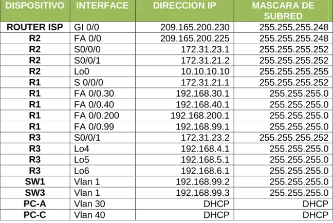
Tabla 4. Direccionamiento Escenario 2.
DISPOSITIVO INTERFACE DIRECCION IP MASCARA DE
SUBRED
ROUTER ISP GI 0/0 209.165.200.230 255.255.255.248
R2 FA 0/0 209.165.200.225 255.255.255.248
R2 S0/0/0 172.31.23.1 255.255.255.252
R2 S0/0/1 172.31.21.2 255.255.255.252
R2 Lo0 10.10.10.10 255.255.255.255
R1 S 0/0/0 172.31.21.1 255.255.255.252
R1 FA 0/0.30 192.168.30.1 255.255.255.0
R1 FA 0/0.40 192.168.40.1 255.255.255.0
R1 FA 0/0.200 192.168.200.1 255.255.255.0
R1 FA 0/0.99 192.168.99.1 255.255.255.0
R3 S0/0/1 172.31.23.2 255.255.255.252
R3 Lo4 192.168.4.1 255.255.255.0
R3 Lo5 192.168.5.1 255.255.255.0
R3 Lo6 192.168.6.1 255.255.255.0
SW1 Vlan 1 192.168.99.2 255.255.255.0
SW3 Vlan 1 192.168.99.3 255.255.255.0
PC-A Vlan 30 DHCP DHCP
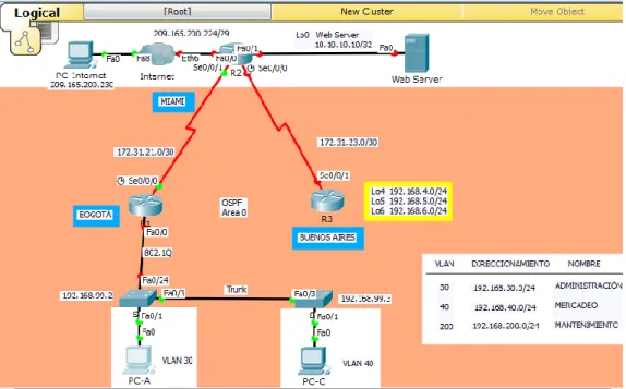
Imagen 14. Escenario 2
2. Configurar el protocolo de enrutamiento OSPFv2 bajo los siguientes criterios:
Tabla 5. OSPFv2 área 0
Configuration Item or Task Specification
Router ID R1 1.1.1.1
Router ID R2 5.5.5.5
Router ID R3 8.8.8.8
Configurar todas las interfaces LAN como pasivas
Establecer el ancho de banda para enlaces seriales en
256 Kb/s
Configuración R1
R1#config t
Enter configuration commands, one per line. End with CNTL/Z. R1(config)#router ospf 1
R1(config-router)#router-id 1.1.1.1 R1(config-router)#exit
R1(config)#router ospf 1
R1(config-router)#do show ip route connected C 172.31.21.0/30 is directly connected, Serial0/0/0 R1(config-router)#network 172.31.21.0 0.0.0.3 area 0 R1(config-router)#router ospf 1
R1(config-router)#exit R1(config)#router ospf 1
R1(config-router)#passive-interface f0/0 R1(config-router)#exit
R1(config)#int s0/0/0
R1(config-if)#bandwidth 256 R1(config-if)#exit
R1(config)#int s0/0/0
R1(config-if)#ip ospf cost 9500 R1(config-if)#exit
Configuración R2
R2#config t
Enter configuration commands, one per line. End with CNTL/Z. R2(config)#router ospf 1
R2(config-router)#router-id 5.5.5.5 R2(config-router)#exit
R2(config)#router ospf 1
R2(config-router)#do show ip route connected C 10.10.10.10/32 is directly connected, Loopback0 C 172.31.21.0/30 is directly connected, Serial0/0/1 C 172.31.23.0/30 is directly connected, Serial0/0/0
C 209.165.200.0/24 is directly connected, FastEthernet0/0 R2(config-router)#
R2(config-router)#network 172.31.21.0 0.0.0.3 area 0 R2(config-router)#networ
R2(config-router)#network 172.31.23.0 0.0.0.3 area 0 R2(config-router)#exit
R2(config)#router ospf 1
R2(config-router)#passive-interface f0/0 R2(config-router)#exit
R2(config)#int s0/0/0
R2(config-if)#bandwidth 256 R2(config-if)#ip ospf cost 9500 R2(config-if)#exit
Configuración R3
R3#config t
Enter configuration commands, one per line. End with CNTL/Z. R3(config)#router ospf 1
R3(config-router)#router-id 8.8.8.8 R3(config-router)#exit
R3(config)#router ospf 1
R3(config-router)#do show ip route connected C 172.31.23.0/30 is directly connected, Serial0/0/1 C 192.168.4.0/24 is directly connected, Loopback4 C 192.168.5.0/24 is directly connected, Loopback5 C 192.168.6.0/24 is directly connected, Loopback6 R3(config-router)#network 172.31.23.0 0.0.0.3 area 0 R3(config-router)#exit
R3(config)#route
01:41:05: %OSPF-5-ADJCHG: Process 1, Nbr 5.5.5.5 on Serial0/0/1 from LOADING to FULL, Loading Done
R3(config)#router ospf 1
R3(config-router)#passive-interface f0/0 R3(config-router)#exit
R3(config)#int s0/0/1
Verificar información de OSPF
Visualizar tablas de enrutamiento y routers conectados por OSPFv2 Visualizar lista resumida de interfaces por OSPF en donde se ilustre el costo de cada interface
Visualizar el OSPF Process ID, Router ID, Address summarizations, Routing Networks, and passive interfaces configuradas en cada router.
Imagen 15. Comando Show ip route en R1
Imagen 17. Comando Show ip ospf interface s0/0/0 en R1
Imagen 18. Comando Show ip protocols R1
Imagen 20. Comando Show ip ospf en R2
Imagen 21. Comando Show ip ospf interface s0/0/0
Imagen 23. Comando Show ip route
Imagen 24. Comando Show ip ospf
Imagen 26. Comando Show ip protocols
3. Configurar VLANs, Puertos troncales, puertos de acceso, encapsulamiento, Inter-VLAN Routing y Seguridad en los Switches acorde a la topología de red establecida.
S1 S2
S1#config t
Enter configuration commands, one per line. End with CNTL/Z.
S1(config)#int vlan 1 S1(config-if)#ip address 192.168.99.2 255.255.255.0 S1(config-if)#no sh
S1(config-if)#
%LINK-5-CHANGED: Interface Vlan1, changed state to up
%LINEPROTO-5-UPDOWN: Line protocol on Interface Vlan1, changed state to up
S1(config-if)# S1(config)#vlan 30
S3#config t
Enter configuration commands, one per line. End with CNTL/Z.
S3(config)#vlan 30 S3(config-vlan)#name Administracion S3(config-vlan)#vlan 40 S3(config-vlan)#name Mercadeo S3(config-vlan)#vlan 200 S3(config-vlan)#name Mantenimiento S3(config-vlan)#exit S3(config)#int fa0/1 S3(config-if)#exit S3(config)#int f0/1 S3(config-if)#swi
S3(config-if)#switchport mode access S3(config-if)#switchport access vlan 40 S3(config-if)#exit
S3(config)#
S1(config-vlan)#name Administracion S1(config-vlan)#vlan 40 S1(config-vlan)#name Mercadeo S1(config-vlan)#vlan 200 S1(config-vlan)#name Mantenimiento S1(config-vlan)#exit S1(config)#int f0/1 S1(config-if)#swi S1(config-if)#switchport mode access S1(config-if)#swi
S1(config-if)#switchport access vlan 30
S1(config-if)#exit
S1(config)#int vlan 30 S1(config-if)#
%LINK-5-CHANGED: Interface Vlan30, changed state to up %LINEPROTO-5-UPDOWN: Line protocol on Interface Vlan30, changed state to up
S1(config-if)#ip address 192.168.30.2 255.255.255128 ^
% Invalid input detected at ‘^’ marker.
S1(config-if)#ip address
192.168.30.2 255.255.255.128 S1(config-if)#no sh
S1(config-if)#exit S1(config)#int vlan 40 S1(config-if)#
%LINK-5-CHANGED: Interface Vlan40, changed state to up S1(config-if)#ip address
192.168.40.126 255.255.255.128 S1(config-if)#no sh
S3(config-if)#
%LINK-5-CHANGED: Interface Vlan30, changed state to up
S3(config-if)#ip address 192.168.30.2 255.255.255.128
S3(config-if)#no sh S3(config-if)#exit S3(config)#int vlan 40 S3(config-if)#
%LINK-5-CHANGED: Interface Vlan40, changed state to up
%LINEPROTO-5-UPDOWN: Line protocol on Interface Vlan40, changed state to up
S3(config-if)#ip address 192.168.40.126 255.255.255.128
S3(config-if)#no sh S3(config-if)#exit S3(config)#int vlan 200 S3(config-if)#
%LINK-5-CHANGED: Interface Vlan200, changed state to up S3(config-if)#ip address 192.168.200.126 255.255.255.128 S3(config-if)#no sh S3(config-if)#exit S3(config)# S3#config t
Enter configuration commands, one per line. End with CNTL/Z.
S3(config)#int fa0/1 S3(config-if)#swi
S3(config-if)#switchport mode access S3(config-if)#swi
S3(config-if)#switchport access vlan 40 S3(config-if)#
S3(config)#int fa0/3 S3(config-if)#swi
S1(config-if)#exit S1(config)#int vlan 200 S1(config-if)#
%LINK-5-CHANGED: Interface Vlan200, changed state to up S1(config-if)#ip address
192.168.200.126 255.255.255.128 S1(config-if)#no sh
S1#config t
Enter configuration commands, one per line. End with CNTL/Z.
S1(config)#int fa0/24 S1(config-if)#swi
S1(config-if)#switchport mode trunk S1(config-if)#int fa0/1
S1(config-if)#exit S1(config)#int fa0/3 S1(config-if)#swi
S1(config-if)#switchport mode trunk S1(config-if)#
%LINEPROTO-5-UPDOWN: Line protocol on Interface
FastEthernet0/3, changed state to down
%LINEPROTO-5-UPDOWN: Line protocol on Interface Vlan1, changed state to down
%LINEPROTO-5-UPDOWN: Line protocol on Interface
FastEthernet0/3, changed state to up
S3(config-if)#exit
R1#config t
Enter configuration commands, one per line. End with CNTL/Z. R1(config)#int fa0/0.3
R1(config-subif)#encap
R1(config-subif)#exit R1(config)#int fa0/0.1 R1(config-subif)#enc
R1(config-subif)#encapsulation dot1q 1
R1(config-subif)#ip address 192.168.99.1 255.255.255.128 R1(config-subif)#int fa0/0.30
R1(config-subif)#enca
R1(config-subif)#encapsulation dot1q 30
R1(config-subif)#ip address 192.168.30.1 255.255.255.128 R1(config-subif)#int fa0/0.40
R1(config-subif)#encap
R1(config-subif)#encapsulation dot1q40 ^
% Invalid input detected at ‘^’ marker. R1(config-subif)#enca
R1(config-subif)#encapsulation dotq 40 ^
% Invalid input detected at ‘^’ marker. R1(config-subif)#encapsulation dot1q 40
R1(config-subif)#ip address 192.168.40.1 255.255.255.128 R1(config-subif)#int fa0/0.200
R1(config-subif)#enca
R1(config-subif)#encapsulation dot1q 200
R1(config-subif)#ip address 192.168.200.1 255.255.255.128 R1(config-subif)#exit
R1(config)#int fa0/0 R1(config-if)#no sh R1(config-if)#
%LINK-5-CHANGED: Interface FastEthernet0/0, changed state to up
%LINEPROTO-5-UPDOWN: Line protocol on Interface FastEthernet0/0, changed state to up
%LINK-5-CHANGED: Interface FastEthernet0/0.1, changed state to up %LINEPROTO-5-UPDOWN: Line protocol on Interface FastEthernet0/0.1, changed state to up
%LINEPROTO-5-UPDOWN: Line protocol on Interface FastEthernet0/0.30, changed state to up
%LINK-5-CHANGED: Interface FastEthernet0/0.40, changed state to up %LINEPROTO-5-UPDOWN: Line protocol on Interface FastEthernet0/0.40, changed state to up
%LINK-5-CHANGED: Interface FastEthernet0/0.200, changed state to up %LINEPROTO-5-UPDOWN: Line protocol on Interface FastEthernet0/0.200, changed state to up
Imagen 27. Comando Show ip route a R1
4. En el Switch 3 deshabilitar DNS lookup
5. Asignar direcciones IP a los Switches acorde a los lineamientos.
6. Desactivar todas las interfaces que no sean utilizadas en el esquema de red. 7. Implement DHCP and NAT for Ipv4
R1#config t
Enter configuration commands, one per line. End with CNTL/Z. R1(config)#ip dhcp excluded-address 192.168.30.1 192.168.30.30 R1(config)#ip dhcp pool ADMINISTRACION
R1(dhcp-config)#network 192.168.30.0 255.255.255.0 R1(dhcp-config)#default-router 192.168.30.1
R1(dhcp-config)#dns-server 10.10.10.11 R1(dhcp-config)#end
R1#
%SYS-5-CONFIG_I: Configured from console by console R1#config t
Enter configuration commands, one per line. End with CNTL/Z. R1(config)#ip dhcp excluded-address 192.168.40.1 192.168.40.30 R1(config)#ip dhcp pool MERCADEO
R1(dhcp-config)#network 192.168.40.0 255.255.255.0 R1(dhcp-config)#default-router 192.168.40.1
R1(dhcp-config)#dns-server 10.10.10.11 R1(dhcp-config)#end
R1#
%SYS-5-CONFIG_I: Configured from console by console
9. Reservar las primeras 30 direcciones IP de las VLAN 30 y 40 para configuraciones estáticas.
Configurar DHCP pool para VLAN 30
Name: ADMINISTRACION DNS-Server: 10.10.10.11 Domain-Name: ccna-unad.com Establecer default gateway. Configurar DHCP pool
para VLAN 40
Name: MERCADEO DNS-Server: 10.10.10.11 Domain-Name: ccna-unad.com Establecer default gateway.
R1(config)#ip dhcp excluded-address 192.168.30.1 192.168.30.30 R1(config)#ip dhcp pool ADMINISTRACION
R1(dhcp-config)#network 192.168.30.0 255.255.255.0 R1(dhcp-config)#default-router 192.168.30.1
R1(dhcp-config)#dns-server 10.10.10.11 R1(dhcp-config)#END
%SYS-5-CONFIG_I: Configured from console by console R1#CONFIG T
Enter configuration commands, one per line. End with CNTL/Z. R1(config)#ip dhcp excluded-address 192.168.40.1 192.168.40.30 R1(config)#ip dhcp pool MERCADEO
R1(dhcp-config)#network 192.168.40.0 255.255.255.0 R1(dhcp-config)#default-router 192.168.40.1
R1(dhcp-config)#dns-server 10.10.10.11 R1(dhcp-config)#end
10. Configurar NAT en R2 para permitir que los host puedan salir a internet
R1#config t
Enter configuration commands, one per line. End with CNTL/Z. R1(config)#ip route 0.0.0.0 0.0.0.0 172.31.21.2
R1(config)#exit R1#
%SYS-5-CONFIG_I: Configured from console by console R1#show ip route static
S* 0.0.0.0/0 [1/0] via 172.31.21.2
11. Configurar al menos dos listas de acceso de tipo estándar a su criterio en para restringir o permitir tráfico desde R1 o R3 hacia R2.
R2(config)#access-list 1 permit 192.168.99.0 0.0.0.255
R2(config)#ip nat pool public_access 209.165.201.225 209.165.201.230 netmask 255.255.255.248
12. Configurar al menos dos listas de acceso de tipo extendido o nombradas a su criterio en para restringir o permitir tráfico desde R1 o R3 hacia R2.
Imagen 28. Ping de R1 a R2
Imagen 29. Ping de R2 a R1
Imagen 30. Ping de R2 a R3
Imagen 32. Ping de R3 a R2
Archivos de configuración escenario 2
Se anexa los archivos de configuración de los dispositivos de la red del Escenario 2.
R1
R1#show running-config Building configuration…
Current configuration : 1898 bytes !
version 12.4
no service timestamps log datetime msec no service timestamps debug datetime msec no service password-encryption
!
hostname R1 !
enable secret 5 $1$mERr$9cTjUIEqNGurQiFU.ZeCi1 enable password cisco
! !
ip dhcp excluded-address 192.168.30.1 192.168.30.30 ip dhcp excluded-address 192.168.40.1 192.168.40.30 !
ip dhcp pool ADMINISTRACION network 192.168.30.0 255.255.255.0 default-router 192.168.30.1
dns-server 10.10.10.11 ip dhcp pool MERCADEO
network 192.168.40.0 255.255.255.0 default-router 192.168.40.1
dns-server 10.10.10.11 !
no ip cef no ipv6 cef !
!
no ip domain-lookup !
!
!
interface FastEthernet0/0 no ip address
duplex auto speed auto !
interface FastEthernet0/0.1 encapsulation dot1Q 1 native
ip address 192.168.99.1 255.255.255.128 !
interface FastEthernet0/0.3 no ip address
!
interface FastEthernet0/0.30 encapsulation dot1Q 30
ip address 192.168.30.1 255.255.255.128 !
interface FastEthernet0/0.40 encapsulation dot1Q 40
ip address 192.168.40.1 255.255.255.128 !
interface FastEthernet0/0.200 encapsulation dot1Q 200
ip address 192.168.200.1 255.255.255.128 !
interface FastEthernet0/1 no ip address
duplex auto speed auto shutdown ! interface Serial0/0/0 bandwidth 256
ip address 172.31.21.1 255.255.255.252 ip ospf cost 9500
clock rate 128000 !
interface Serial0/0/1 no ip address
clock rate 2000000 shutdown
!
!
router ospf 1 router-id 1.1.1.1
log-adjacency-changes
passive-interface FastEthernet0/0 network 172.31.21.0 0.0.0.3 area 0 !
ip classless
ip route 0.0.0.0 0.0.0.0 172.31.21.2 ¡
ip flow-export 55ersión 9 ¡
¡
banner motd ^Cadvertencia… el ingreso es solo para personal autorizado^C ¡
¡
line con 0 password cisco login
!
line aux 0 !
line vty 0 4 password cisco login
line vty 5 15 password cisco login
! ! ! end
R2
R2#show running-config Building configuration…
Current configuration : 1347 bytes !
no service timestamps debug datetime msec no service password-encryption
!
hostname R2 !
!
enable secret 5 $1$mERr$9cTjUIEqNGurQiFU.ZeCi1 enable password cisco
! !
no ip cef no ipv6 cef !
! !
no ip domain-lookup !
!
spanning-tree mode pvst !
! !
interface Loopback0
ip address 10.10.10.10 255.255.255.255 !
interface FastEthernet0/0
ip address 209.165.200.225 255.255.255.248 duplex auto
speed auto ipv6 ospf cost 1 !
interface FastEthernet0/1 no ip address
duplex auto speed auto !
interface Serial0/0/0 bandwidth 256
ip address 172.31.23.1 255.255.255.252 ip ospf cost 9500
clock rate 128000 !
interface Serial0/0/1 bandwidth 256
ip ospf cost 9500 clock rate 2000000 !
interface Vlan1 no ip address shutdown !
router ospf 1 router-id 5.5.5.5
log-adjacency-changes
passive-interface FastEthernet0/0 network 172.31.21.0 0.0.0.3 area 0 network 172.31.23.0 0.0.0.3 area 0 !
ip classless
ip route 209.165.200.224 255.255.255.252 172.31.21.1 !
ip flow-export version 9 ¡
¡
banner motd ^Cadvertencia el Ingreso es solo para personal Autorizado^C !
!
line con 0 password cisco logging synchronous login
!
line aux 0 !
line vty 0 4 password cisco login
Building configuration…
Current configuration : 1300 bytes !
version 12.4
no service timestamps log datetime msec no service timestamps debug datetime msec no service password-encryption
!
hostname R3 !
!
enable secret 5 $1$mERr$9cTjUIEqNGurQiFU.ZeCi1 enable password cisco
! !
no ip cef no ipv6 cef !
!
no ip domain-lookup !
!
spanning-tree mode pvst !
!
interface Loopback4
ip address 192.168.4.1 255.255.255.0 !
interface Loopback5
ip address 192.168.5.1 255.255.255.0 !
interface Loopback6
ip address 192.168.6.1 255.255.255.0 !
interface FastEthernet0/0 no ip address
duplex auto speed auto shutdown !
interface FastEthernet0/1 no ip address
shutdown !
interface Serial0/0/0 no ip address
clock rate 2000000 shutdown
!
interface Serial0/0/1 bandwidth 256
ip address 172.31.23.2 255.255.255.252 ip ospf cost 9500
clock rate 2000000 !
interface Vlan1 no ip address shutdown !
router ospf 1 router-id 8.8.8.8
log-adjacency-changes
passive-interface FastEthernet0/0 network 172.31.23.0 0.0.0.3 area 0 ¡
ip classless !
ip flow-export version 9 ¡
¡
banner motd ^Cadvertencia el Ingreso es solo para personal Autorizado^C !
!
line con 0 password cisco logging synchronous login
!
line aux 0 !
line vty 0 4 password cisco login
end
S1
S1#show running-config Building configuration…
Current configuration : 1751 bytes !
version 12.2
no service timestamps log datetime msec no service timestamps debug datetime msec no service password-encryption
!
hostname S1 !
enable secret 5 $1$mERr$9cTjUIEqNGurQiFU.ZeCi1 enable password cisco
! !
no ip domain-lookup !
!
spanning-tree mode pvst !
interface FastEthernet0/1 switchport access vlan 30 switchport mode access !
interface FastEthernet0/2 shutdown
!
!
interface FastEthernet0/23 shutdown
!
interface FastEthernet0/24 switchport mode trunk ! interface GigabitEthernet0/1 ! interface GigabitEthernet0/2 ! interface Vlan1
ip address 192.168.99.2 255.255.255.0 ¡
interface Vlan30
ip address 192.168.30.2 255.255.255.128 !
interface Vlan40
ip address 192.168.40.126 255.255.255.128 !
interface Vlan99 no ip address !
interface Vlan200
ip address 192.168.200.126 255.255.255.128 !
ip default-gateway 192.168.99.1 !
banner motd ^Cbienvenido^C !
! !
line con 0
logging synchronous !
line vty 0 4 login
line vty 5 15 login
! ! end
S3#show running-config Building configuration…
Current configuration : 1679 bytes !
version 12.2
no service timestamps log datetime msec no service timestamps debug datetime msec no service password-encryption
!
hostname S3 !
enable secret 5 $1$mERr$hx5rVt7rPNoS4wqbXKX7m0 enable password class
! !
no ip domain-lookup !
!
spanning-tree mode pvst !
interface FastEthernet0/1 switchport access vlan 40 switchport mode access !
interface FastEthernet0/2 shutdown
!
shutdown !
interface FastEthernet0/24 shutdown
!
interface GigabitEthernet0/1 !
interface GigabitEthernet0/2 !
interface Vlan1
ip address 192.168.99.3 255.255.255.0 !
interface Vlan30
ip address 192.168.30.2 255.255.255.128 !
interface Vlan40
ip address 192.168.40.126 255.255.255.128 !
interface Vlan200
ip address 192.168.200.126 255.255.255.128 ¡
ip default-gateway 192.168.99.1 !
!
line con 0
logging synchronous !
line vty 0 4 login
line vty 5 15 login
CONCLUSIONES
Mediante el desarrollo del presente trabajo se puso a prueba las habilidades adquiridas durante los cursos de CCNA 1 y CCNA 2, ya que fue posible configurar diversos dispositivos y utilizar protocolos de enrutamiento y servicios, mediante el uso de la herramienta Packet Tracer.
En el desarrollo del Escenario 1 se implementó NAT, se configuró y se puso en funcionamiento el Servidor DHCP, al igual que RIPv2 y el routing entre VLAN, entre otras configuraciones básicas.
En el Escenario 2 se configuraron los dispositivos para conectarlos entre sí, se implementó el protocolo de enrutamiento OSPFv2, al igual que se configuró DHCP VLAN 30 y VLAN 40, además se realizó la configuración NAT en R2 y otras configuraciones básicas en todos los dispositivos.
BIBLIOGRAFIA
https://www.cisco.com/c/en/us/support/docs/ip/open-shortest-path-first-ospf/7039-1.html
https://todopacketracer.com/2011/10/18/configuracion-de-vlans/
https://www.cisco.com/c/en/us/td/docs/ios-xml/ios/iproute_ospf/configuration/xe-3s/iro-xe-3s-book/iro-mode-ospfv2.html
https://www.eduangi.org/node186.html
https://www.cisco.com/c/es_mx/support/docs/quality-of-service-qos/qos-packet-marking/10100-priorityvsbw.html
https://interpolados.wordpress.com/2017/05/01/configuracion-de-interfaces-pasivas/