CURSO DE PROFUNDIZACION CISCO (DISEÑO E IMPLEMENTACIÓN DE SOLUCIONES INTEGRADAS LAN – WAN)
PRUEBA DE HABILIDADES PRACTICA
JANITH SULAY JAIMES PABON Grupo: 203092_9
UNIVERSIDAD NACIONAL ABIERTA Y A DISTANCIA UNAD FACULTAD DE CIENCIAS BASICAS TECNOLOGIA E INGENIERIA
CURSO DE PROFUNDIZACION CISCO (DISEÑO E IMPLEMENTACIÓN DE SOLUCIONES INTEGRADAS LAN – WAN)
PRUEBA DE HABILIDADES PRACTICA
JANITH SULAY JAIMES PABON Grupo: 203092_9
Diplomado de profundización para optar el título de INGENIERA DE SISTEMAS
Tutor:
ING.GERARDO GRANADOS ACUÑA
UNIVERSIDAD NACIONAL ABIERTA Y A DISTANCIA UNAD- FACULTAD DE CIENCIAS BASICAS TECNOLOGIA E INGENIERIA
3
NOTA DE ACEPTACIÓN
Firma del Presidente de Jurado
Firma del Jurado
Firma del Jurado
4
TABLA DE CONTENIDO
Pág.
LISTA DE TABLAS ... 6
LISTA DE FIGURAS ... 7
INTRODUCCIÓN ... 10
OBJETIVOS ... 11
OBJETIVO GENERAL: ... 11
1ESCENARIO 1 ... 12
1.1 PARTE 1: CONFIGURACIÓN DEL ENRUTAMIENTO……….21
1.2 PARTE 2: TABLA DE ENRUTAMIENTO……….23
1.3 PARTE 3 DESHABILITAR LA PROPAGACIÓN DEL PROTOCOLO RIP. ... 28
1.4 PARTE 4 VERIFICACIÓN DEL PROTOCOLO RIP………..29
1.5 PARTE 5 CONFIGURAR ENCAPSULAMIENTO Y AUTENTICACIÓN PP…..34
1.6 PARTE 6: CONFIGURACIÓN DE PAT………36
1.7PARTE 7: CONFIGURACIÓN DEL SERVICIO DHCP………..38
2ESCENARIO 2 ... 41
DESARROLLO DE LA ACTIVIDAD ... 42
2.1CONFIGURAR EL DIRECCIONAMIENTO IP ACORDE CON LA TOPOLOGÍA DE RED PARA CADA UNO DE LOS DISPOSITIVOS QUE FORMAN PARTE DEL ESCENARIO ... 42
2.2 CONFIGURAR EL PROTOCOLO DE ENRUTAMIENTO OSPFV2 BAJO LOS SIGUIENTES CRITERIOS ... 47
2.3 CONFIGURAR VLANS, PUERTOS TRONCALES, PUERTOS DE ACCESO, ENCAPSULAMIENTO, INTER-VLAN ROUTING Y SEGURIDAD EN LOS SWITCHES ACORDE A LA TOPOLOGÍA DE RED ESTABLECIDA. ... 53
2.4EN EL SWITCH 3 DESHABILITAR DNS LOOKUP ... 54
5
6
LISTA DE TABLAS
Pág.
TABLA 1: SUBREDES EN LA TOPOLOGÍA DEL ESCENARIO 1 ... 14
TABLA 2: DIRECCIONES IP EN LA TOPOLOGÍA DEL ESCENARIO 1. ... 15
TABLA 3: INTERFACES QUE NO NECESITAN DESACTIVAR PROPAGACIÓN DE RIP - 2. ... 28
TABLA 4:SUBREDES EN LA TOPOLOGÍA DEL ESCENARIO 2 ... 43
TABLA 5:DIRECCIONES IP LAN EN LA TOPOLOGÍA DEL ESCENARIO 2. ... 43
TABLA 6:DIRECCIONES IP WAN EN LA TOPOLOGÍA DEL ESCENARIO 2. ... 44
TABLA 7:CRITERIOS DE CONFIGURACIÓN DE PROTOCOLO OSPV V2. ... 47
7
LISTA DE FIGURAS
Pág.
ILUSTRACIÓN 1: TOPOLOGÍA ESCENARIO 1 ... 12
ILUSTRACIÓN 2:TOPOLOGÍA DE RED EJERCICIO 1. ... 13
ILUSTRACIÓN 3: INDICACIÓN DE REDES MEDELLÍN Y BOGOTÁ EN EJERCICIO 1. ... 13
ILUSTRACIÓN 4: TOPOLOGÍA DE RED EJERCICIO 1 SIN CONECTIVIDAD. ... 20
ILUSTRACIÓN 5: TOPOLOGÍA DE RED EJERCICIO 1 CON CONECTIVIDAD. . 20
ILUSTRACIÓN 6: RESUMEN CONFIGURACIÓN ROUTER MEDELLIN 1. ... 21
ILUSTRACIÓN 7: RESUMEN CONFIGURACIÓN ROUTER BOGOTA 1. ... 22
ILUSTRACIÓN 8: TABLA DE ENRUTAMIENTO ROUTER ISP. ... 23
ILUSTRACIÓN 9: TABLA DE ENRUTAMIENTO ROUTER ISP 2. ... 24
ILUSTRACIÓN 10: TABLA DE ENRUTAMIENTO MEDELLIN 1. ... 24
ILUSTRACIÓN 11:TABLA DE ENRUTAMIENTO MEDELLIN 2. ... 25
ILUSTRACIÓN 12: TABLA DE ENRUTAMIENTO MEDELLIN 3. ... 25
ILUSTRACIÓN 13: TABLA DE ENRUTAMIENTO BOGOTA 1. ... 26
ILUSTRACIÓN 14: TABLA DE ENRUTAMIENTO BOGOTA 2. ... 26
ILUSTRACIÓN 15: TABLA DE ENRUTAMIENTO BOGOTA 3. ... 27
ILUSTRACIÓN 16: TABLA DE ENRUTAMIENTO BOGOTA 3 - 2. ... 27
ILUSTRACIÓN 17:TABLA DE ENRUTAMIENTO ISP - 2. ... 28
ILUSTRACIÓN 18: PROTOCOLOS CONFIGURADOS EN ROUTER MEDELLIN 1. ... 30
ILUSTRACIÓN 19: PROTOCOLOS CONFIGURADOS EN ROUTER MEDELLIN 2. ... 30
ILUSTRACIÓN 20: PROTOCOLOS CONFIGURADOS EN ROUTER MEDELLIN 3. ... 31
8
9
ILUSTRACIÓN 37: APLICACIÓN DE DHCP EN HOST DE LA RED LAN DE
MEDELLIN. ... 40
ILUSTRACIÓN 38: APLICACIÓN DE DHCP EN HOST DE LA RED LAN DE BOGOTA... 40
ILUSTRACIÓN 39:TOPOLOGÍA DE RED EJERCICIO # 2. ... 41
ILUSTRACIÓN 40: TOPOLOGÍA DE RED EJERCICIO # 2 APLICADA DEN PACKET TRACER. ... 42
ILUSTRACIÓN 41:TABLA DE ENRUTAMIENTO ROUTER R1. ... 49
ILUSTRACIÓN 42: TABLA DE ENRUTAMIENTO ROUTER R2. ... 50
ILUSTRACIÓN 43: TABLA DE ENRUTAMIENTO ROUTER R3. ... 50
ILUSTRACIÓN 44: TABLA DE ENRUTAMIENTO DE PROTOCOLO OSPF EN ROUTER R2. ... 51
ILUSTRACIÓN 45: TABLA DE ENRUTAMIENTO DE PROTOCOLO OSPF EN ROUTER R1. ... 52
ILUSTRACIÓN 46: TABLA DE ENRUTAMIENTO DE PROTOCOLO OSPF EN ROUTER R2. ... 52
ILUSTRACIÓN 47: TABLA DE ENRUTAMIENTO DE PROTOCOLO OSPF EN ROUTER R3. ... 53
ILUSTRACIÓN 48: PRUEBA DE PING EN PCA. ... 57
ILUSTRACIÓN 49: PRUEBA DE PING EN R1. ... 58
ILUSTRACIÓN 50: PRUEBA DE PING EN R1 - 2. ... 58
ILUSTRACIÓN 51: COMANDO TRACERT EN PC A. ... 59
10
INTRODUCCIÓN
En este trabajo se realizarán la configuración del protocolo de enrutamiento RIP, también se configurará PPP como método de encapsulamiento y autenticación, la cual permite dos tipos diferentes de autenticación: protocolo de autenticación de contraseña PAP y protocolo de autenticación de intercambio de señales CHAP. PAP utiliza una contraseña no cifrada, mientras que CHAP llama un hash de una sola vía que brinda más seguridad que el PAP.
11 OBJETIVOS
OBJETIVO GENERAL:
12
1 ESCENARIO 1
Una empresa posee sucursales distribuidas en las ciudades de Bogotá y Medellín, en donde el estudiante será el administrador de la red, el cual deberá configurar e interconectar entre sí cada uno de los dispositivos que forman parte del escenario, acorde con los lineamientos establecidos para el direccionamiento IP, protocolos de enrutamiento y demás aspectos que forman parte de la topología de red.
Topología de red
Ilustración 1: Topología escenario 1
Este escenario plantea el uso de RIP como protocolo de enrutamiento, considerando que se tendran rutas por defecto redistribuidas; asimismo, habilitar el encapsulamiento PPP y su autenticación.
Los routers Bogota2 y medellin2 proporcionan el servicio DHCP a su propia red LAN y a los routers 3 de cada ciudad.
Debe configurar PPP en los enlaces hacia el ISP, con autenticación. Debe habilitar NAT de sobrecarga en los routers Bogota1 y medellin1.
Desarrollo
Como trabajo inicial se debe realizar lo siguiente.
Realizar las rutinas de diagnóstico y dejar los equipos listos para su configuración (asignar nombres de equipos, asignar claves de seguridad, etc).
13
Configurar la topología de red, de acuerdo con las siguientes especificaciones.
DESARROLLO
Antes que nada, se inicia armando la topología de red.
Ilustración 2:Topología de red ejercicio 1.
Segundo se asigna nombre y además se dejan indicados los rangos IP que se van a emplear dentro de cada una de las LAN.
Ilustración 3: Indicación de redes Medellín y Bogotá en ejercicio 1.
Tabla de Direccionamiento
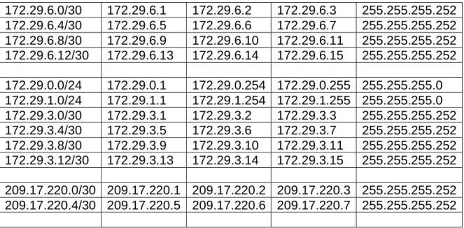
Se comienza identificando cada uno de los rangos de las diferentes SUBREDES.
Dir. red Primera IP Ultma IP Broadcast. Mascara.
14
172.29.6.0/30 172.29.6.1 172.29.6.2 172.29.6.3 255.255.255.252 172.29.6.4/30 172.29.6.5 172.29.6.6 172.29.6.7 255.255.255.252 172.29.6.8/30 172.29.6.9 172.29.6.10 172.29.6.11 255.255.255.252 172.29.6.12/30 172.29.6.13 172.29.6.14 172.29.6.15 255.255.255.252 172.29.0.0/24 172.29.0.1 172.29.0.254 172.29.0.255 255.255.255.0 172.29.1.0/24 172.29.1.1 172.29.1.254 172.29.1.255 255.255.255.0 172.29.3.0/30 172.29.3.1 172.29.3.2 172.29.3.3 255.255.255.252 172.29.3.4/30 172.29.3.5 172.29.3.6 172.29.3.7 255.255.255.252 172.29.3.8/30 172.29.3.9 172.29.3.10 172.29.3.11 255.255.255.252 172.29.3.12/30 172.29.3.13 172.29.3.14 172.29.3.15 255.255.255.252 209.17.220.0/30 209.17.220.1 209.17.220.2 209.17.220.3 255.255.255.252 209.17.220.4/30 209.17.220.5 209.17.220.6 209.17.220.7 255.255.255.252
Tabla 1: Subredes en la topología del escenario 1
Se continúa asignando la IP a cada una de las interfaces que intervienen en la red.
Dispositivo Interface Dirección IP Máscara de Subred
Puerta de Enlace ISP S0/0/0 209.165.200.1 255.255.255.252
S0/0/1 209.165.200.5 255.255.255.252 MEDELLIN1 S0/0/0 209.165.200.2 255.255.255.252 S0/0/1 172.29.6.1 255.255.255.252 S0/1/0 172.29.6.9 255.255.255.252 S0/1/1 172.29.6.13 255.255.255.252 MEDELLIN2 S0/0/0 172.29.6.2 255.255.255.252 S0/0/1 172.29.6.5 255.255.255.252 G0/0 172.29.4.1 255.255.255.128 MEDELLIN3 S0/0/0 172.29.6.10 255.255.255.252 S0/0/1 172.29.6.14 255.255.255.252 S0/1/0 172.29.6.6 255.255.255.252 G0/0 172.29.4.129 255.255.255.128 BOGOTA1 S0/0/0 209.165.200.6 255.255.255.252 S0/0/1 172.29.3.9 255.255.255.252 S0/1/0 172.29.3.1 255.255.255.252 S0/1/1 172.29.3.5 255.255.255.252 BOGOTA2 S0/0/0 172.29.3.10 255.255.255.252 S0/0/1 172.29.3.13 255.255.255.252 G0/0 172.29.1.1 255.255.255.0 BOGOTA3 S0/0/0 172.29.3.2 255.255.255.252
15
S0/1/0 172.29.3.14 255.255.255.252 G0/0 172.29.0.1 255.255.255.0
PC- MEDELLIN2 F0/0 DHCP DHCP DHCP
PC- MEDELLIN3 F0/0 DHCP DHCP DHCP
PC- BOGOTA2 F0/0 DHCP DHCP DHCP
PC- BOGOTA3 F0/0 DHCP DHCP DHCP
Tabla 2: Direcciones IP en la topología del escenario 1.
Como trabajo inicial se debe realizar lo siguiente.
• Realizar las rutinas de diagnóstico y dejar los equipos listos para su configuración (asignar nombres de equipos, asignar claves de seguridad, etc).
IS0050 ISP
hostname ISP no ip domain-lookup
service password-encryption enable secret class
banner motd %Acceso Restringido% ip domain-name cisco.com
line console 0 password cisco login
line vty 0 15 password cisco login
MEDELLIN1
hostname MEDELLIN1 no ip domain-lookup
service password-encryption enable secret class
banner motd %Acceso Restringido% ip domain-name cisco.com
line console 0 password cisco login
16 password cisco
login
MEDELLIN2
hostname MEDELLIN2 no ip domain-lookup
service password-encryption enable secret class
banner motd %Acceso Restringido% ip domain-name cisco.com
line console 0 password cisco login
line vty 0 15 password cisco login
MEDELLIN3
hostname MEDELLIN3 no ip domain-lookup
service password-encryption enable secret class
banner motd %Acceso Restringido% ip domain-name cisco.com
line console 0 password cisco login
line vty 0 15 password cisco login
BOGOTA1
hostname BOGOTA1 no ip domain-lookup
service password-encryption enable secret class
banner motd %Acceso Restringido% ip domain-name cisco.com
17 login
line vty 0 15 password cisco login
BOGOTA2
hostname BOGOTA2 no ip domain-lookup
service password-encryption enable secret class
banner motd %Acceso Restringido% ip domain-name cisco.com
line console 0 password cisco login
line vty 0 15 password cisco login
BOGOTA3
hostname BOGOTA3 no ip domain-lookup
service password-encryption enable secret class
banner motd %Acceso Restringido% ip domain-name cisco.com
line console 0 password cisco login
line vty 0 15 password cisco login
Como en este punto ya conocemos la dirección IP que debemos asignar a cada una de las intefaces, podemos proceder a configurar cada uno de ellos.
ISP
interface Serial0/0/0
18 clock rate 4000000
no shutdown
interface Serial0/0/1
ip address 209.17.220.5 255.255.255.252 clock rate 4000000
no shutdown
MEDELLIN1
interface Serial0/0/0
ip address 209.17.220.2 255.255.255.252 no shutdown
interface Serial0/0/1
ip address 172.29.6.1 255.255.255.252 clock rate 4000000
no shutdown
interface Serial0/1/0
ip address 172.29.6.9 255.255.255.252 clock rate 4000000
no shutdown
interface Serial0/1/1
ip address 172.29.6.13 255.255.255.252 clock rate 4000000
no shutdown
MEDELLIN2
interface GigabitEthernet0/0
ip address 172.29.4.1 255.255.255.128 no shutdown
interface Serial0/0/0
ip address 172.29.6.2 255.255.255.252 no shutdown
interface Serial0/0/1
ip address 172.29.6.5 255.255.255.252 clock rate 4000000
no shutdown
MEDELLIN3
interface GigabitEthernet0/0
19 no shutdown
interface Serial0/0/0
ip address 172.29.6.10 255.255.255.252 no shutdown
interface Serial0/0/1
ip address 172.29.6.14 255.255.255.252 no shutdown
interface Serial0/1/0
ip address 172.29.6.6 255.255.255.252 no shutdown
BOGOTA1
interface Serial0/0/0
ip address 209.17.220.6 255.255.255.252 no shutdown
interface Serial0/0/1
ip address 172.29.3.9 255.255.255.252 no shutdown
interface Serial0/1/0
ip address 172.29.3.1 255.255.255.252 clock rate 4000000
no shutdown
interface Serial0/1/1
ip address 172.29.3.5 255.255.255.252 no shutdown
BOGOTA2
interface GigabitEthernet0/0
ip address 172.29.1.1 255.255.255.0 no shutdown
interface Serial0/0/0
ip address 172.29.3.10 255.255.255.252 no shutdown
interface Serial0/0/1
ip address 172.29.3.13 255.255.255.252 clock rate 4000000
no shutdown
20 interface GigabitEthernet0/0
ip address 172.29.0.1 255.255.255.0 no shutdown
interface Serial0/0/0
ip address 172.29.3.2 255.255.255.252 no shutdown
interface Serial0/0/1
ip address 172.29.3.6 255.255.255.252 no shutdown
interface Serial0/1/0
ip address 172.29.3.14 255.255.255.252 no shutdown
Realizar la conexión fisica de los equipos con base en la topología de red
Ilustración 4: Topología de red ejercicio 1 sin conectividad.
Luego de configurar las diferentes interfaces cada uno de los indicadores de los dispositivos cambia de color:
Ilustración 5: Topología de red ejercicio 1 con conectividad.
21
1.1 PARTE 1: CONFIGURACIÓN DEL ENRUTAMIENTO
a.Configurar el enrutamiento en la red usando el protocolo RIP versión 2, declare la red principal, desactive la sumarización automática.
MEDELLIN1 router rip version 2
network 172.29.0.0 no auto-summary
Ilustración 6: Resumen configuración router MEDELLIN 1.
MEDELLIN2 router rip version 2
network 172.29.0.0 no auto-summary MEDELLIN3 router rip version 2
network 172.29.0.0 no auto-summary BOGOTA1
router rip version 2
22 no auto-summary
Ilustración 7: Resumen configuración router BOGOTA 1.
BOGOTA2 router rip version 2
network 172.29.0.0 no auto-summary BOGOTA3
router rip version 2
network 172.29.0.0 no auto-summary
b.Los routers Bogota1 y Medellín deberán añadir a su configuración de enrutamiento una ruta por defecto hacia el ISP y, a su vez, redistribuirla dentro de las publicaciones de RIP.
MEDELLIN1
ip route 0.0.0.0 0.0.0.0 209.17.220.1 router rip
default-information originate
23 ip route 0.0.0.0 0.0.0.0 209.17.220.5
router rip
default-information originate
c.El router ISP deberá tener una ruta estática dirigida hacia cada red interna de Bogotá y Medellín para el caso se sumarizan las subredes de cada uno a /22. ISP
ip route 172.29.4.0 255.255.252.0 209.17.220.2 ip route 172.29.0.0 255.255.252.0 209.17.220.6
Ilustración 8: Tabla de enrutamiento Router ISP.
1.2 PARTE 2:TABLA DE ENRUTAMIENTO.
24
Ilustración 9: Tabla de enrutamiento router ISP 2.
25
Ilustración 11:Tabla de enrutamiento MEDELLIN 2.
26
Ilustración 13: Tabla de enrutamiento BOGOTA 1.
27
Ilustración 15: Tabla de enrutamiento BOGOTA 3.
b.Verificar el balanceo de carga que presentan los routers.
c.Obsérvese en los routers Bogotá1 y Medellín1 cierta similitud por su ubicación, por tener dos enlaces de conexión hacia otro router y por la ruta por defecto que manejan.
d.Los routers Medellín2 y Bogotá2 también presentan redes conectadas directamente y recibidas mediante RIP.
e.Las tablas de los routers restantes deben permitir visualizar rutas redundantes para el caso de la ruta por defecto.
28
El router ISP solo debe indicar sus rutas estáticas adicionales a las directamente conectadas.
Ilustración 17:Tabla de enrutamiento ISP - 2.
1.3 PARTE 3 DESHABILITAR LA PROPAGACIÓN DEL PROTOCOLO RIP.
a.Para no propagar las publicaciones por interfaces que no lo requieran se debe deshabilitar la propagación del protocolo RIP, en la siguiente tabla se indican las interfaces de cada router que no necesitan desactivación.
ROUTER INTERFAZ
Bogota1 SERIAL0/0/1; SERIAL0/1/0;
SERIAL0/1/1
Bogota2 SERIAL0/0/0; SERIAL0/0/1
Bogota3 SERIAL0/0/0; SERIAL0/0/1;
SERIAL0/1/0
Medellín1 SERIAL0/0/0; SERIAL0/0/1;
SERIAL0/1/1
Medellín2 SERIAL0/0/0; SERIAL0/0/1
Medellín3 SERIAL0/0/0; SERIAL0/0/1;
SERIAL0/1/0
ISP No lo requiere
Tabla 3: Interfaces que no necesitan desactivar propagación de RIP - 2.
29 MEDELLIN1
router rip
passive-interface Serial0/0/0 MEDELLIN2
router rip
passive-interface GigabitEthernet0/0 MEDELLIN3
router rip
passive-interface GigabitEthernet0/0
BOGOTA1 router rip
passive-interface Serial0/0/0 BOGOTA2
router rip
passive-interface GigabitEthernet0/0 BOGOTA3
router rip
passive-interface GigabitEthernet0/0
1.4 PARTE 4 VERIFICACIÓN DEL PROTOCOLO RIP.
30
Ilustración 18: Protocolos configurados en router MEDELLIN 1.
31
Ilustración 20: Protocolos configurados en router MEDELLIN 3.
32
Ilustración 22: Protocolos configurados en router BOGOTA 2.
Ilustración 23: Protocolos configurados en router BOGOTA 3.
33
Ilustración 24: Tabla de enrutamiento protocolo RIP V2 en router MEDELLIN 1.
Ilustración 25: Tabla de enrutamiento protocolo RIP V2 en router MEDELLIN 2.
Ilustración 26: Tabla de enrutamiento protocolo RIP V2 en router MEDELLIN 3.
34
Ilustración 28: Tabla de enrutamiento protocolo RIP V2 en router BOGOTA 2.
Ilustración 29: Tabla de enrutamiento protocolo RIP V2 en router BOGOTA 3.
1.5 PARTE 5 CONFIGURAR ENCAPSULAMIENTO Y AUTENTICACIÓN PPP.
a.Según la topología se requiere que el enlace Medellín1 con ISP sea configurado con autenticación PAP.
ISP
username MEDELLIN password cisco interface Serial0/0/0
encapsulation ppp ppp authentication pap
ppp pap sent-username ISP password cisco
MEDELLIN1
username ISP password cisco interface Serial0/0/0
encapsulation ppp ppp authentication pap
ppp pap sent-username MEDELLIN password cisco
35 ISP
username BOGOTA password cisco interface Serial0/0/1
encapsulation ppp ppp authentication chap BOGOTA1
username ISP password cisco interface Serial0/0/0
encapsulation ppp ppp authentication chap
36
Ilustración 31:Configuración de protocolo PPP – PAP en MEDELLIN 1.
Ilustración 32: Configuración de protocolo PPP – CHAP en BOGOTA 1.
1.6 PARTE 6: CONFIGURACIÓN DE PAT.
a. En la topología, si se activa NAT en cada equipo de salida (Bogotá1 y Medellín1), los routers internos de una ciudad no podrán llegar hasta los routers internos en el otro extremo, sólo existirá comunicación hasta los routers Bogotá1, ISP y Medellín1. b. Después de verificar lo indicado en el paso anterior proceda a configurar el NAT en el router Medellín1. Compruebe que la traducción de direcciones indique las interfaces de entrada y de salida. Al realizar una prueba de ping, la dirección debe ser traducida automáticamente a la dirección de la interfaz serial 0/1/0 del router Medellín1, cómo diferente puerto.
37
ip nat inside source list 1 interface Serial0/0/0 overload access-list 1 permit 172.29.4.0 0.0.3.255
interface Serial0/0/0 ip nat outside
interface Serial0/0/1 ip nat inside
interface Serial0/1/0 ip nat inside
interface Serial0/1/1 ip nat inside
Ilustración 33: traducción de direcciones de protocolo NAT en MEDELLIN 1.
c.Proceda a configurar el NAT en el router Bogotá1. Compruebe que la traducción de direcciones indique las interfaces de entrada y de salida. Al realizar una prueba de ping, la dirección debe ser traducida automáticamente a la dirección de la interfaz serial 0/1/0 del router Bogotá1, cómo diferente puerto.
BOGOTA1
ip nat inside source list 1 interface Serial0/0/0 overload access-list 1 permit 172.29.0.0 0.0.3.255
interface Serial0/0/0 ip nat outside
interface Serial0/0/1 ip nat inside
interface Serial0/1/0 ip nat inside
38
Ilustración 34: traducción de direcciones de protocolo NAT en BOGOTA 1.
1.7 PARTE 7: CONFIGURACIÓN DEL SERVICIO DHCP.
a.Configurar la red Medellín2 y Medellín3 donde el router Medellín 2 debe ser el servidor DHCP para ambas redes Lan.
MEDELLIN2
ip dhcp excluded-address 172.29.4.1 172.29.4.5 ip dhcp excluded-address 172.29.4.129 172.29.4.133 ip dhcp pool MED2
network 172.29.4.0 255.255.255.128 default-router 172.29.4.1
dns-server 8.8.8.8 ip dhcp pool MED3
network 172.29.4.128 255.255.255.128 default-router 172.29.4.129
dns-server 8.8.8.8
39
b.El router Medellín3 deberá habilitar el paso de los mensajes broadcast hacia la IP del router Medellín2.
MEDELLIN3
interface GigabitEthernet0/0 ip helper-address 172.29.6.5
c.Configurar la red Bogotá2 y Bogotá3 donde el router Bogotá2 debe ser el servidor DHCP para ambas redes Lan.
BOGOTA2
ip dhcp excluded-address 172.29.1.1 172.29.1.5 ip dhcp excluded-address 172.29.0.1 172.29.0.5 ip dhcp pool BOG2
network 172.29.1.0 255.255.255.0 default-router 172.29.1.1
dns-server 8.8.8.8 ip dhcp pool BOG3
network 172.29.0.0 255.255.255.0 default-router 172.29.0.1
dns-server 8.8.8.8
Ilustración 36: Configuración de protocolo DHCP en router BOGOTA 2.
d.Configure el router Bogotá1 para que habilite el paso de los mensajes Broadcast hacia la IP del router Bogotá2.
BOGOTA3
40 ip helper-address 172.29.3.13
Ilustración 37: Aplicación de DHCP en host de la red LAN de MEDELLIN.
41
2 ESCENARIO 2
Escenario: Una empresa de Tecnología posee tres sucursales distribuidas en las ciudades de Miami, Bogotá y Buenos Aires, en donde el estudiante será el
administrador de la red, el cual deberá configurar e interconectar entre sí cada uno de los dispositivos que forman parte del escenario, acorde con los lineamientos establecidos para el direccionamiento IP, protocolos de enrutamiento y demás aspectos que forman parte de la topología de red.
42
DESARROLLO DE LA ACTIVIDAD.
Ilustración 40: Topología de red ejercicio # 2 aplicada den packet tracer.
2.1 CONFIGURAR EL DIRECCIONAMIENTO IP ACORDE CON LA
TOPOLOGÍA DE RED PARA CADA UNO DE LOS DISPOSITIVOS QUE FORMAN PARTE DEL ESCENARIO
Rangos IP:
Según la topología se muestra los rangos para cada una de las subredes serían los siguientes:
Dir. red Primera IP Ultma IP Broadcast. Mascara. 192.168.99.0/24 192.168.99.1 192.168.99.2
54
192.168.99.2 55
255.255.255. 0
192.168.4.0/24 192.168.4.1 192.168.4.25 4
192.168.4.25 5
255.255.255. 0
192.168.5.0/24 192.168.5.1 192.168.5.25 4
192.168.5.25 5
255.255.255. 0
43
172.31.21.0/30 172.31.21.1 172.31.21.2 172.31.21.3 255.255.255. 252
172.31.23.0/30 172.31.23.1 172.31.23.2 172.31.23.3 255.255.255. 252
Tabla 4:Subredes en la topología del escenario 2
Como ya se tienen los rangos se procede a asignar las direcciones IP a cada una de las interfaces que intervienen y los PC.
Tabla de Direccionamiento
Dispositivo Interface Dirección IP Máscara de Subred
Puerta de Enlace
VLAN
R1 G0/0.30 192.168.30.1 255.255.255.0 30
G0/0.40 192.168.40.1 255.255.255.0 40 G0/0.99 192.168.200.1 255.255.255.0 99 S0/0/0 172.31.21.1 255.255.255.252
R2 G0/0 209.165.200.22
S0/0/0 172.31.21.2 255.255.255.252 S0/0/1 172.31.23.1 255.255.255.252 Loopback
0
10.10.10.10 255.255.255.255 R3 S0/0/1 172.31.23.2 255.255.255.252
Loopback 4
192.168.4.1 255.255.255.0 Loopback
5
192.168.5.1 255.255.255.0 Loopback
6
192.168.6.1 255.255.255.0
S1 VLAN 99 192.168.200.2 255.255.255.0 99
S3 VLAN 99 192.168.200.3 255.255.255.0 99
PC-A F0/0 DHCP DHCP DHCP 30
PC-B F0/0 DHCP DHCP DHCP 40
Tabla 5:Direcciones IP LAN en la topología del escenario 2.
Tabla de VLAN
VLAN Nombre Subred Puertos
30 ADMINISTRACION 192.168.30.0/24 S1 - F0/1
44
99 MANTENIMIENTO 192.168.200.0/24
Tabla 6:Direcciones IP WAN en la topología del escenario 2.
R1
hostname R1 enable secret class no ip domain-lookup
interface GigabitEthernet0/0 no shutdown
interface GigabitEthernet0/0.31 description Accounting LAN encapsulation dot1Q 30
ip address 192.168.30.1 255.255.255.0 interface GigabitEthernet0/0.33
description Engineering LAN encapsulation dot1Q 40
ip address 192.168.40.1 255.255.255.0 interface GigabitEthernet0/0.99
description Managemment LAN encapsulation dot1Q 99
ip address 192.168.200.1 255.255.255.0 interface Serial0/0/0
description Conneciton to R2
ip address 172.31.21.1 255.255.255.252 clock rate 128000
no shutdown
ip route 0.0.0.0 0.0.0.0 Serial0/0/0 banner motd ^C
Unauthorized Access is Prohibited! ^C line con 0
exec-timeout 0 0 password cisco logging synchronous login
line vty 0 4 password cisco login
R2
service password-encryption hostname R2
45 interface Loopback0
description Simulated Web Server
ip address 10.10.10.10 255.255.255.255 interface GigabitEthernet0/0
description conneciton to ISP
ip address 209.165.200.225 255.255.255.248 no shutdown
interface Serial0/0/0
description Connection to R1
ip address 172.31.21.2 255.255.255.252 no shutdown
interface Serial0/0/1
description Conneciton to R3
ip address 172.31.23.1 255.255.255.252 clock rate 128000
no shutdown
ip route 0.0.0.0 0.0.0.0 GigabitEthernet0/0 banner motd ^C
Unauthorized Access is Prohibited! ^C line con 0
exec-timeout 0 0 password cisco logging synchronous login
line vty 0 4
access-class ADMIN-MGT-R1 in password cisco
login
line vty 5 15
access-class ADMIN-MGT-R3 in password cisco
login
R3
service password-encryption hostname R3
enable secret class no ip domain-lookup interface Loopback4
ip address 192.168.4.1 255.255.255.0 interface Loopback5
46 ip address 192.168.6.1 255.255.255.0 interface Serial0/0/1
description Connection to R2
ip address 172.31.23.2 255.255.255.252 no shutdown
ip route 0.0.0.0 0.0.0.0 Serial0/0/1 banner motd ^C
Unauthorized Access is Prohibited! ^C line con 0
exec-timeout 0 0 password cisco logging synchronous login
line vty 0 4 password cisco login
S1
hostname S1 enable secret class no ip domain-lookup banner motd ^C
Unauthorized Access is Prohibited! ^C line con 0
password cisco logging synchronous login
exec-timeout 0 0 line vty 0 4 password cisco login
S3
hostname S3 enable secret class banner motd ^C
Unauthorized Access is Prohibited! ^C line con 0
47 exec-timeout 0 0
line vty 0 4 password cisco login
2.2 CONFIGURAR EL PROTOCOLO DE ENRUTAMIENTO OSPFV2 BAJO LOS SIGUIENTES CRITERIOS
OSPFv2 area 0
Configuration Item or Task Specification
Router ID R1 1.1.1.1
Router ID R2 5.5.5.5
Router ID R3 8.8.8.8
Configurar todas las interfaces LAN como pasivas
Establecer el ancho de banda para enlaces
seriales en 256 Kb/s
Ajustar el costo en la métrica de S0/0 a 9500
Tabla 7:Criterios de configuración de protocolo OSPV V2.
R1
router ospf 1 router-id 1.1.1.1
log-adjacency-changes
passive-interface GigabitEthernet0/0.30 passive-interface GigabitEthernet0/0.40 passive-interface GigabitEthernet0/0.99 auto-cost reference-bandwidth 1000 network 172.31.21.0 0.0.0.3 area 0 network 192.168.30.0 0.0.0.255 area 0 network 192.168.40.0 0.0.0.255 area 0 network 192.168.200.0 0.0.0.255 area 0 interface Serial0/0/0
bandwidth 256 ip ospf cost 7500 R2
router ospf 1 router-id 5.5.5.5
log-adjacency-changes passive-interface Loopback0
48 network 10.10.10.10 0.0.0.0 area 0
network 172.31.21.0 0.0.0.3 area 0 network 172.31.23.0 0.0.0.3 area 0 interface Serial0/0/0
bandwidth 256 ip ospf cost 9500 interface Serial0/0/1 bandwidth 256 ip ospf cost 9500 R3
router ospf 1 router-id 8.8.8.8
log-adjacency-changes passive-interface Loopback4 passive-interface Loopback5 passive-interface Loopback6
auto-cost reference-bandwidth 1000 network 172.31.23.0 0.0.0.3 area 0 network 192.168.4.0 0.0.3.255 area 0 interface Serial0/0/1
49 Verificar información del OSPF
Visualizar tablas de enrutamiento y routers conectados por OSPFv2
50
Ilustración 42: Tabla de enrutamiento router R2.
51
Visualizar lista resumida de interfaces por OSPF en donde se ilustre el costo de cada interface
Ilustración 44: Tabla de enrutamiento de protocolo OSPF en router R2.
52
Ilustración 45: Tabla de enrutamiento de protocolo OSPF en router R1.
53
Ilustración 47: Tabla de enrutamiento de protocolo OSPF en router R3.
2.3 CONFIGURAR VLANS, PUERTOS TRONCALES, PUERTOS DE ACCESO, ENCAPSULAMIENTO, INTER-VLAN ROUTING Y SEGURIDAD EN LOS SWITCHES ACORDE A LA TOPOLOGÍA DE RED ESTABLECIDA.
S1 vlan 30
name ADMINISTRACION vlan 40
name MERCADEO vlan 99
name MANTENIMIENTO interface FastEthernet0/1 switchport access vlan 30 switchport mode access
interface range FastEthernet0/2, FastEthernet0/4-23, GigabitEthernet0/1-2 switchport mode access
54 S3 vlan 30 name ADMINISTRACION vlan 40 name MERCADEO vlan 99 name MANTENIMIENTO interface FastEthernet0/1 switchport access vlan 40 switchport mode access
interface FastEthernet0/2, FastEthernet0/4-24, GigabitEthernet0/1-2 switchport mode access
interface FastEthernet0/3 switchport mode trunk
2.4 EN EL SWITCH 3 DESHABILITAR DNS LOOKUP
S3
no ip domain-lookup
2.5 ASIGNAR DIRECCIONES IP LAN A LOS SWITCHES ACORDE A LOS LINEAMIENTOS.
S1
interface Vlan99
ip address 192.168.200.2 255.255.255.0 no shutdown
ip default-gateway 192.168.200.1 S3
interface Vlan99
ip address 192.168.200.3 255.255.255.0 no shutdown
55
2.6 DESACTIVAR TODAS LAS INTERFACES QUE NO SEAN UTILIZADAS EN EL ESQUEMA DE RED.
S1
interface range FastEthernet0/2, FastEthernet0/4-23, GigabitEthernet0/1-2 shutdown
S3
interface FastEthernet0/2, FastEthernet0/4-24, GigabitEthernet0/1-2 shutdown
2.7 IMPLEMENT DHCP AND NAT FOR IPV4
2.8 CONFIGURAR R1 COMO SERVIDOR DHCP PARA LAS VLANS 30 Y 40.
2.9 RESERVAR LAS PRIMERAS 30 DIRECCIONES IP DE LAS VLAN 30 Y 40
PARA CONFIGURACIONES ESTÁTICAS.
Configurar DHCP pool para VLAN 30
Name: ADMINISTRACION DNS-Server: 10.10.10.11 Domain-Name: ccna-unad.com Establecer default gateway.
Configurar DHCP pool para VLAN 40
Name: MERCADEO DNS-Server: 10.10.10.11 Domain-Name: ccna-unad.com Establecer default gateway.
Tabla 8: Criterios de configuración de protocolo OSPV V2.
R1
ip dhcp excluded-address 192.168.30.1 192.168.30.30 ip dhcp excluded-address 192.168.40.1 192.168.40.30 !
ip dhcp pool ADMINISTRACION network 192.168.30.0 255.255.255.0 default-router 192.168.30.1
dns-server 10.10.10.11 ip dhcp pool MERCADEO
network 192.168.40.0 255.255.255.0 default-router 192.168.40.1
56
2.10 CONFIGURAR NAT EN R2 PARA PERMITIR QUE LOS HOST PUEDAN SALIR A INTERNET
R2
ip nat pool INTERNET 209.165.200.225 209.165.200.228 netmask 255.255.255.248 ip nat inside source list 1 pool INTERNET
access-list 1 permit 192.168.30.0 0.0.0.255 access-list 1 permit 192.168.40.0 0.0.0.255 access-list 1 permit 192.168.4.0 0.0.3.255 interface Loopback0
ip nat inside
interface GigabitEthernet0/0 ip nat outside
interface Serial0/0/0 ip nat inside
interface Serial0/0/1 ip nat inside
2.11 . CONFIGURAR AL MENOS DOS LISTAS DE ACCESO DE TIPO
ESTÁNDAR A SU CRITERIO EN PARA RESTRINGIR O PERMITIR TRÁFICO DESDE R1 O R3 HACIA R2.
R2
ip access-list standard ADMIN-MGT-R1 permit host 172.31.21.1
ip access-list standard ADMIN-MGT-R3 permit host 172.31.23.2
line vty 0 4
access-class ADMIN-MGT-R1 in line vty 5 15
access-class ADMIN-MGT-R3 in
2.12 CONFIGURAR AL MENOS DOS LISTAS DE ACCESO DE TIPO
57 R2
access-list 101 permit tcp any host 209.165.200.229 eq www access-list 101 permit icmp any any echo-reply
access-list 101 deny ip any any
access-list 102 permit tcp any any eq www access-list 102 permit icmp any any echo access-list 102 deny ip any any
interface GigabitEthernet0/0 ip access-group 101 in interface Serial0/0/1 ip access-group 101 in
2.13 VERIFICAR PROCESOS DE COMUNICACIÓN Y REDIRECCIONAMIENTO DE TRÁFICO EN LOS ROUTERS MEDIANTE EL USO DE PING Y
TRACEROUTE.
58
Ilustración 49: Prueba de ping en R1.
59
Ilustración 51: Comando tracert en PC A.
60
CONCLUSIONES
Con el desarrollo de la actividad se logró configurar en cada uno de los escenarios los diferentes protocolos permitiendo conocer su funcionamiento.
A través de estos escenarios su puso en práctica los conocimientos adquiridos durante el desarrollo de las 3 unidades que componían el curso, en la cual se concluye que:
Con el uso del protocolo de enrutamiento RIP cada router conoce los router que están cerca y las direcciones que posee cada uno, también sabe a que distancia se encuentra cada router.
Que Las Vlan proveen una forma de separar grupos de hosts con objetivos diferentes, aunque estos se encuentren conectados al mismo switch. A su vez, en este punto, permite optimizar los puertos de switch. Las Vlan proporcionan una optimización de los recursos físicos.
Que el protocolo OSPF, se diferencia de RIP porque incluye un elemento diferente en su configuración y es el concepto de Área. Un área es una red o un conjunto de redes inmediatas. También se podría decir que un área es una subred en la red WAN. Teniendo en cuenta que el concepto de área sólo se aplica a routers.
61
BIBLIOGRAFÍA
UNAD (2014). PING y TRACER como estrategia en procesos de Networking [OVA]. Recuperado de https://1drv.ms/u/s!AmIJYei-NT1IhgTCtKY-7F5KIRC3
CISCO. (2014). Enrutamiento Dinámico. Principios de Enrutamiento y Conmutación.
Recuperado de
https://static-course-assets.s3.amazonaws.com/RSE50ES/module7/index.html#7.0.1.1
CISCO. (2014). OSPF de una sola área. Principios de Enrutamiento y Conmutación.
Recuperado de
https://static-course-assets.s3.amazonaws.com/RSE50ES/module8/index.html#8.0.1.1
CISCO. (2014). Listas de control de acceso. Principios de Enrutamiento y
Conmutación. Recuperado de
https://static-course-assets.s3.amazonaws.com/RSE50ES/module9/index.html#9.0.1.1
CISCO. (2014). DHCP. Principios de Enrutamiento y Conmutación. Recuperado de
https://static-course-assets.s3.amazonaws.com/RSE50ES/module10/index.html#10.0.1.1
CISCO. (2014). VLANs. Principios de Enrutamiento y Conmutación. Recuperado de
https://static-course-assets.s3.amazonaws.com/RSE50ES/module3/index.html#3.0.1.1
CISCO. (2014). Enrutamiento Estático. Principios de Enrutamiento y Conmutación.
Recuperado de
https://static-course-assets.s3.amazonaws.com/RSE50ES/module6/index.html#6.0.1.1
62
CISCO. (2014). Conceptos de Routing. Principios de Enrutamiento y Conmutación.
Recuperado de