SOLUCIÓN DE ESTUDIOS DE CASO BAJO EL USO DE TECNOLOGÍA CISCO
ROLANDO JAVIER BARRIOS MEZA
UNIVERSIDAD NACIONAL ABIERTA Y A DISTANCIA – UNAD ESCUELA DE CIENCIAS BÁSICAS TECNOLOGÍAS E INGENIERÍAS
SOLUCIÓN DE ESTUDIOS DE CASO BAJO EL USO DE TECNOLOGÍA CISCO
ROLANDO JAVIER BARRIOS MEZA
Diplomado de profundización Cisco (Diseño e implementación de soluciones integradas LAN/WAN) para optar el título de Ingeniero de Sistemas
Director
Ing. JUAN CARLOS VESGA
UNIVERSIDAD NACIONAL ABIERTA Y A DISTANCIA – UNAD ESCUELA DE CIENCIAS BÁSICAS TECNOLOGÍAS E INGENIERÍAS
CONTENIDO
pág.
INTRODUCCIÓN 3
1. DESARROLLO DEL ESCENARIO PROPUESTO NÚMERO 1 4
1.1 SITUACIÓN 6
1.2. DESCRIPCIÓN DE LAS ACTIVIDADES 6
1.2.1 SW1 VLAN y las asignaciones de puertos de VLAN deben cumplir con la tabla 1.
6
1.2.2 Los puertos de red que no se utilizan se deben deshabilitar 7
1.2.3 La información de dirección IP R1, R2 y R3 debe cumplir con la tabla 1.
8
1.2.4 Laptop20, Laptop21, PC20, PC21, Laptop30, Laptop31, PC30 y PC31 deben obtener información IPv4 del servidor DHCP
10
1.2.5 R1 debe realizar una NAT con sobrecarga sobre una dirección IPv4 pública. Asegúrese de que todos los terminales pueden comunicarse con Internet pública (haga ping a la dirección ISP) y la lista de acceso estándar se llama INSIDE-DEVS.
11
1.2.6 R1 debe tener una ruta estática predeterminada al ISP que se configuró y que incluye esa ruta en el dominio RIPv2.
12
1.2.7 R2 es un servidor de DHCP para los dispositivos conectados al puerto FastEthernet0/0
13
1.2.8 R2 debe, además de enrutamiento a otras partes de la red, ruta entre las VLAN 100 y 200.
13
1.2.9 El Servidor0 es sólo un servidor IPv6 y solo debe ser accesibles para los dispositivos en R3 (ping).
14
1.2.10 La NIC instalado en direcciones IPv4 e IPv6 de Laptop30, de Laptop31, de PC30 y obligación de configurados PC31 simultáneas (dual-stack). Las direcciones se deben configurar mediante DHCP y DHCPv6
1.2.11 La interfaz FastEthernet 0/0 del R3 también deben tener direcciones IPv4 e IPv6 configuradas (dual- stack).
14
1.2.12 R1, R2 y R3 intercambian información de routing mediante RIP versión 2
15
1.2.13 R1, R2 y R3 deben saber sobre las rutas de cada uno y la ruta predeterminada desde R1
17
1.2.14 Verifique la conectividad. Todos los terminales deben poder hacer ping entre sí y a la dirección IP del ISP. Los terminales bajo el R3 deberían poder hacer IPv6-ping entre ellos y el servidor.
19
2. DESARROLLO DEL ESCENARIO PROPUESTO NÚMERO 2 20
2.1 SITUACIÓN 20
2.2. DESCRIPCIÓN DE LAS ACTIVIDADES 21
2.2.1 Configurar el direccionamiento IP acorde con la topología de red para cada uno de los dispositivos que forman parte del escenario
21
2.2.2 Configurar el protocolo de enrutamiento OSPFv2 26
2.2.3 Verificar información de OSPF 29
2.2.4. Configurar VLANs, Puertos troncales, puertos de acceso, encapsulamiento, Inter - VLAN Routing y Seguridad en los Switches acorde a la topología de red establecida.
30
2.2.5 En el Switch 3 deshabilitar DNS LOOKUP 38
2.2.6 Asignar direcciones IP a los Switches acorde a los lineamientos 38
2.2.7 Desactivar todas las interfaces que no sean utilizadas en el esquema de red
39
2.2.8 Implemente DHCP and NAT for IPV4 41
2.2.9 Configurar R1 como servidor DHCP para las VLANs 30 y 40 41
2.2.10 Reservar las primeras 30 direcciones IP de las VLAN 30 y 40 para configuraciones estáticas
42
internet
2.2.12 Configurar al menos dos listas de acceso de tipo estándar a su criterio en para restringir o permitir tráfico desde R1 o R3 hacia R2
45
2.2.13 Configurar al menos dos listas de acceso de tipo extendido o nombradas a su criterio en para restringir o permitir tráfico desde R1 o R3 hacia R2
45
2.2.14 Verificar procesos de comunicación y redireccionamiento de tráfico en los routers mediante el uso de Ping y Traceroute
46
CONCLUSION 49
LISTA DE TABLAS
pág.
Tabla 1. Tabla de direccionamiento 4
Tabla 2. Asignación de VLAN y de puertos 5
LISTA DE ILUSTRACIONES
pág.
Ilustración 1. Topología Escenario 1 4
Ilustración 2. Ping dirección ISP 12
Ilustración 3. Ping PC31 ISP 19
Ilustración 4. Ping Laptop21 ISP 19
Ilustración 5. Topología escenario 2 20
Ilustración 6. Lista OSPF 29
Ilustración 7. OSPF procesos 30
Ilustración 8. Comando ping en R1 46
Ilustración 9. Comando ping en R2 47
Ilustración 10. Comando ping en Internet PC 48
RESUMEN
La tecnología es un instrumento primordial hoy en día en el cumplimiento de los objetivos trazados a nivel académico y profesional, brindando instrumentos para facilitar la ejecución de tareas complejas, que sin la ayuda tecnológica se completarían en un periodo de tiempo largo. La Prueba de habilidades practicas es una opción de grado para los estudiantes que cursan el último semestre de Ingeniería de Sistemas en la Universidad Nacional Abierta y a Distancia, la cual dispone de una serie de actividades que se deben desarrollar con los contenidos vistos a lo largo del Diplomado como la configuración del direccionamiento IP de una red determinada, estructurar el enrutamiento OSPFv2 bajo parámetros establecidos, con el fin de que el estudiante adquiera las destrezas para desempeñarse en el mundo laboral de una forma eficaz y eficiente, acorde con el mundo de las tecnologías actuales.
ABSTRAC
Technology is a fundamental instrument nowadays in the fulfillment of the objectives set at the academic and professional level, providing instruments to facilitate the execution of complex tasks, which without the technological help would be completed in a long period of time. The Practical Skills Test is a degree option for students who are studying the last semester of Systems Engineering at the National Open and Distance University, which has a series of activities that must be developed with the contents seen throughout the course. Diploma as the configuration of the IP addressing of a given network, structure the OSPFv2 routing under established parameters, in order that the student acquires the skills to perform in the working world in an effective and efficient way, according to the world of technologies current
3
INTRODUCCIÓN
Las redes de computadoras son un elemento importante de los sistemas informáticos, casi que todas las actividades que son mediadas por ordenadores tienen un nexo con las redes.
La Evaluación de Habilidades prácticas busca profundizar en temáticas importantes y fortalecimiento de competencias para dar solución en el área de redes informáticas a diferentes retos especialmente usando tecnologías de punta como CISCO.
4
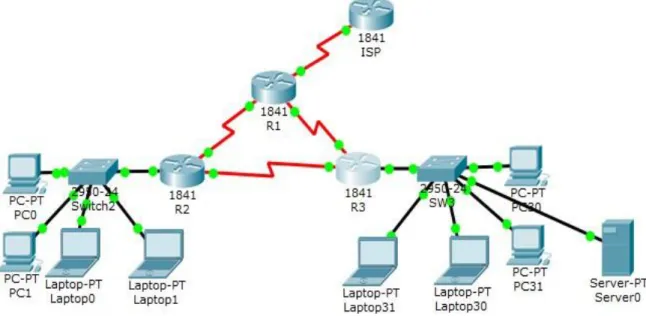
1. DESARROLLO DEL ESCENARIO PROPUESTO NÚMERO 1
Ilustración 1. Topología Escenario 1
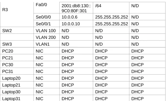
Tabla 1. Tabla de direccionamiento
El
administrador Interfaces Dirección IP
Máscara de subred
Gateway predeterminado
ISP S0/0/0 200.123.211.1 255.255.255.0 N/D
R1
Se0/0/0 200.123.211.2 255.255.255.0 N/D
Se0/1/0 10.0.0.1 255.255.255.252 N/D
Se0/1/1 10.0.0.5 255.255.255.252 N/D
R2
Fa0/0,100 192.168.20.1 255.255.255.0 N/D
Fa0/0,200 192.168.21.1 255.255.255.0 N/D
Se0/0/0 10.0.0.2 255.255.255.252 N/D
Se0/0/1 10.0.0.9 255.255.255.252 N/D
5
PC20 NIC DHCP DHCP DHCP
PC21 NIC DHCP DHCP DHCP
PC30 NIC DHCP DHCP DHCP
PC31 NIC DHCP DHCP DHCP
Laptop20 NIC DHCP DHCP DHCP
Laptop21 NIC DHCP DHCP DHCP
Laptop30 NIC DHCP DHCP DHCP
Laptop31 NIC DHCP DHCP DHCP
Tabla 2. Asignación de VLAN y de puertos
Dispositivo VLAN Nombre Interfaz
SW2 100 LAPTOPS Fa0/2-3
SW2 200 DESTOPS Fa0/4-5
SW3 1 - Todas las interfaces
Tabla 3. Enlaces troncales R3
Fa0/0 2001:db8:130::
9C0:80F:301
/64 N/D
Se0/0/0 10.0.0.6 255.255.255.252 N/D
Se0/0/1 10.0.0.10 255.255.255.252 N/D
SW2 VLAN 100 N/D N/D N/D
VLAN 200 N/D N/D N/D
SW3 VLAN1 N/D N/D N/D
Dispositivo local Interfaz local Dispositivo remoto
6 1.1 SITUACIÓN
En esta actividad, demostrará y reforzará su capacidad para implementar NAT, servidor de DHCP, RIPV2 y el routing entre VLAN, incluida la configuración de direcciones IP, las VLAN, los enlaces troncales y las subinterfaces. Todas las pruebas de alcance deben realizarse a través de ping únicamente.
1.2. DESCRIPCIÓN DE LAS ACTIVIDADES
1.2.1 SW1 VLAN y las asignaciones de puertos de VLAN se realizan de acuerdo a la tabla 1.
En SW2: Previamente se cambia el nombre del dispositivo con el comando Hostname, después se inicia la configuración de interfaces
SW2>enable
SW2#configure terminal
SW2(config)#vlan 100
SW2(config-vlan)#name LAPTOPS SW2(config-vlan)#exit
SW2(config)#vlan 200
SW2(config-vlan)#name DESTOPS SW2(config-vlan)#exit
SW2(config)#interface range fa0/2 - 3
SW2(config-if-range)# switchport mode trunk
SW2(config-if-range)#switchport trunk native vlan 100 SW2(config-if-range)#no shutdown
7 SW2(config)#interface range fa0/4 – 5
SW2(config-if-range)#port access vlan 200
SW2(config-if-range)#no shutdown SW2(config-if-range)#exit
SW2(config)#interface fa0/1
SW2(config-if)#switchport mode trunk
Procedimiento en SW3:
SW3
SW3 (config)# int range f0/1-24
SW3 (config-if-range)# switchport mode Access
SW3 (config-if-range)# switchport Access vlan 1 SW3 (config-if-range)# exit
1.2.2 Los puertos de red que no se utilizan se deshabilitan
Procedimiento en SW2:
SW2 # configure terminal
SW2 (config) # int range f0/6-24 (Los puertos del 1 al 5 se están utilizando) SW2 (config-if-range) #shutdown
SW2 (config-if-range) # exit SW2 (config) end
8 Procedimiento en SW3:
SW3 # configure terminal
SW3 (config) # int range f0/6-23 SW3 (config-if-range) #shutdown SW3 (config-if-range) # exit SW3 (config) end
SW3# wr
1.2.3 La información de dirección IP R1, R2 y R3 se configura para que cumpla con la tabla 1.
Para R1:
Router(config)#hostname R1 R1(config)#interface Serial0/0/0
R1(config-if)#ip address 200.123.211.2 255.255.255.0
R1(config-if)#no shutdown (Para activar física y lógicamente la interface) R1(config-if)#exit
R1(config)#interface Serial0/1/0
R1(config-if)#ip address 10.0.0.1 255.255.255.252 R1(config-if)#no shutdown
R1(config)#interface Serial0/1/1
R1(config-if)#ip address 10.0.0.5 255.255.255.252 R1(config-if)#no shutdown
9 Para R2:
Router(config)#hostname R2 R2(config)#interface Serial0/0/0
R2(config-if)#ip address 10.0.0.2 255.255.255.252 R2(config-if)#no shutdown
R2(config-if)#exit
R2(config)#interface Serial0/0/1
R2(config-if)#ip address 10.0.0.9 255.255.255.252
R2(config-if)#no shutdown R2(config-if)#exit
Para R3:
Router(config)#hostname R3 R3(config)#interface Serial0/0/0
R3(config-if)#ip address 10.0.0.6 255.255.255.252
R3(config-if)#no shutdown R3(config-if)#exit
R3(config)#interface Serial0/0/1
R3(config-if)#ip address 10.0.0.10 255.255.255.252 R3(config-if)#no shutdown
10
1.2.4 Laptop20, Laptop21, PC20, PC21, Laptop30, Laptop31, PC30 y PC31 deben obtener información IPv4 del servidor DHCP
En R2:
Router>en
Router#conf
Router(config)#hostname R2
R2(config)#ip dhcp pool vlan_100 (Se obtiene información de Vlan diferentes)
R2(dhcp-config)#network 192.168.20.1 255.255.255.0 R2(dhcp-config)#default-router 192.168.21.1
R2(dhcp-config)#exit R2(config)#
En R3:
Router>en
Router#conf t
Router(config)#hostname R3 R3(config)#ip dhcp pool vlan_1
R3(dhcp-config)#network 192.168.30.1 255.255.255.0 R3(dhcp-config)#default-router 192.168.30.1
R3(dhcp-config)#ipv6 dhcp pool vlan_1
R3(config-dhcpv6)#dns-server 2001:db8:130:: R3(config-dhcpv6)#exit
11
1.2.5 R1 debe realizar una NAT con sobrecarga sobre una dirección IPv4 pública. Asegúrese de que todos los terminales pueden comunicarse con Internet pública (haga ping a la dirección ISP) y la lista de acceso estándar se llama INSIDE-DEVS.
Con los siguientes comandos se crea una lista de control:
R1(config)#ip nat pool INSIDE-DEVS 200.123.211.2 200.123.211.128 netmask 255.255.255.0
R1(config)#access-list 1 permit 192.168.0.0 0.0.255.255 R1(config)#access-list 1 permit 10.0.0.0 0.0.0.255
R1(config)#ip nat inside source list 1 interface s0/0/0 overload (Se da salida a internet por medio de varios puertos)
R1(config-if)#interfa s0/0/0 R1(config-if)#ip nat outside
R1(config-if)#interfa s0/1/0 R1(config-if)#ip nat inside R1(config-if)#interfa s0/1/1
12 Ilustración 2. Ping dirección ISP
1.2.6 R1 debe tener una ruta estática predeterminada al ISP que se configuró y que incluye esa ruta en el dominio RIPv2.
R1(config)#router rip
R1(config-router)#version 2
R1(config-router)#ip route 0.0.0.0 0.0.0.0 s0/0/0
R1(config)#router rip
R1(config-router)#version 2
R1(config-router)#network 10.0.0.4
R1(config-router)#network 10.0.0.0
13
1.2.7 R2 es un servidor de DHCP para los dispositivos conectados al puerto FastEthernet0/0
Las dos direcciones iniciales on excluidas.
R2(config)#ip dhcp excluded-address 192.168.20.1 R2(config)#ip dhcp excluded-address 192.168.21.1 R2(config)#ip dhcp pool fa0/0.100
R2(dhcp-config)#network 192.168.20.0 255.255.255.0 R2(dhcp-config)#default-router 192.168.20.1
R2(dhcp-config)#dns-server 200.123.211.1 R2(dhcp-config)#exit
R2(config)#ip dhcp pool fa0/0.200
R2(dhcp-config)#network 192.168.21.0 255.255.255.0 R2(dhcp-config)#default-router 192.168.21.1
R2(dhcp-config)#dns-server 200.123.211.1
R2(dhcp-config)#
1.2.8 R2 debe, además de enrutamiento a otras partes de la red, ruta entre las VLAN 100 y 200.
R2(config)# int vlan 100
R2(config-if)# ip address 192.168.20.1 255.255.255.0 R2(config-if )# int vlan 200
R2(config-if)# ip address 192.168.20.1 255.255.255.0
14
1.2.9 El Servidor0 es sólo un servidor IPv6 y solo debe ser accesibles para los dispositivos en R3 (ping).
R3(config)#ipv6 unicast-routing R3(config)#interface fa0/0
R3(config-if)#ip address 192.168.20.1 255.255.255.0
R3(config-if)#ipv6 address 2001:db8:130::9C0:80F:301/64 R3(config-if)#ipv6 dhcp server vlan_1
R3(config-if)#ipv6 nd other-config-flag R3(config-if)#no shutdown
R3(config-if)#exit
1.2.10 La NIC instalado en direcciones IPv4 e IPv6 de Laptop30, de Laptop31, de PC30 y obligación de configurados PC31 simultáneas (dual-stack). Las direcciones se deben configurar mediante DHCP y DHCPv6
R1(config)# router rip
R1(config-router)# versión 2
Imagen 8. Ejecución del comando Show ip route connected en el R1 R1(config-router)# network 10.0.0.0
R1(config-router)# network 10.0.0.4
1.2.11 La interfaz FastEthernet 0/0 del R3 también deben tener direcciones IPv4 e IPv6 configuradas (dual- stack).
R3>
15 R3#configure terminal
R3 (config) #ipv6 unicast-routing
R3 (config) #int f0/0
R3 (config-if) # ipv6 enable
R3 (config-if) # ip address 192.168.30.1 255.255.255.0 R3 (config-if) # ipv6 address 2001:db9: : 9c0: 80F:301/64
R3 (config-if) # no shutdown
1.2.12 R1, R2 y R3 intercambian información de routing mediante RIP versión 2
En R1:
R1#config
R1(config)#router rip
R1(config-router)#version 2
R1(config-router)#do show ip route connected C 10.0.0.0/30 is directly connected, Serial0/1/0
C 10.0.0.4/30 is directly connected, Serial0/1/1 R1(config-router)#network 10.0.0.0
R1(config-router)#network 10.0.0.4
16 En R2:
R2#config
R2(config)#router rip
R2(config-router)#version 2
R2(config-router)#network 10.0.0.0
R1(config-router)#network 10.0.0.8 R2(config-router)#network 192.168.20.0 R2(config-router)#network 192.168.21.0
R2(config-router)#network 192.168.30.0 R2(config-router)#network 200.123.211.0 R2(config-router)#do show ip route connected
C 10.0.0.0/30 is directly connected, Serial0/0/0 C 10.0.0.8/30 is directly connected, Serial0/0/1
C 192.168.20.0/24 is directly connected, FastEthernet0/0.100 C 192.168.21.0/24 is directly connected, FastEthernet0/0.200 R2(config-router)#end
En R3:
R3(config)#router rip
R3(config-router)#version 2
R3(config-router)#network 10.0.0.4
17 R3(config-router)#network 192.168.30.0 R3(config-router)#network 200.123.211.0
R3(config-router)#end
R3#show ip route connected
C 10.0.0.4/30 is directly connected, Serial0/0/0 C 10.0.0.8/30 is directly connected, Serial0/0/1
C 192.168.30.0/24 is directly connected, FastEthernet0/0
1.2.13 R1, R2 y R3 deben saber sobre las rutas de cada uno y la ruta predeterminada desde R1.
En R1:
R1>enable
R1 #
R1 # configure term R1 (config) # router rip
R1 (config-router) # version 2
R1 (config-router) #network 10.0.0.0 R1 (config-router) #network 10.0.0.4
18 En R2:
R2>enable R2 #
R2 # configure terminal R2 (config) # router rip
R2 (config-router) # version 2 R2(config-router) #network 10.0.0.0 R2 (config-router) #network 10.0.0.8
R2 (config-router) # do show ip route connected R2 (config-router) #end
En R3:
R3>enable R3 #
R3 # configure terminal
R3 (config) # router rip
R3 (config-router) # version 2
R3 (config-router) #network 10.0.0.0
R3 (config-router) #network 10.0.0.8
19
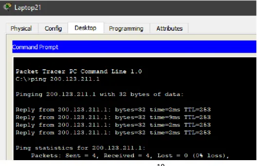
1.2.14 Verifique la conectividad. Todos los terminales deben poder hacer ping entre sí y a la dirección IP del ISP. Los terminales bajo el R3 deberían poder hacer IPv6-ping entre ellos y el servidor.
Ilustración 3. Ping PC31 ISP
20
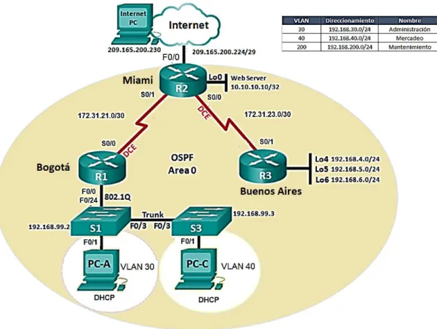
2. DESARROLLO DEL ESCENARIO PROPUESTO NÚMERO 2
Ilustración 5. Topología escenario 2
2.1 SITUACIÓN
21 2.2. DESCRIPCIÓN DE LAS ACTIVIDADES
2.2.1 Configurar el direccionamiento IP acorde con la topología de red para cada uno de los dispositivos que forman parte del escenario
2.2.1.1 Configuración PC-A:
Habilitar DHCP en PC-A IP Address: 169.254.238.140 Subnet Mask: 255.255.0.0
2.2.1.2 Configuración PC-C:
Habilitar DHCP en PC-C IP Address: 169.254.67.198 Subnet Mask: 255.255.0.0
2.2.1.3 Configuración Internet-PC:
Static
IP Address: 209.165.200.230 Subnet Mask: 255.255.255.248 Defaul gateway: 209.165.200.255
IPv6 Address: 2001:DB8:ACAD:2::30/64 Subnet Mask: 255.255.255.248
22 2.2.1.4 Configuración de R1
Router>en Router#conf t
Enter configuration commands, one per line. End with CNTL/Z. Router(config)#no ip domain-lookup
Router(config)#hostname R1 R1(config)#enable secret class R1(config)#line con
% Incomplete command. R1(config)#line con 0 R1(config-line)#pass cisco R1(config-line)#login R1(config-line)#line vty 0 4 R1(config-line)#pass cisco R1(config-line)#login R1(config-line)#exit
R1(config)#service password-encryption
R1(config)#banner motd $Acceso no Autorizado$ R1(config)#int s0/0/0
R1(config-if)#ip address 172.31.21.1 255.255.255.252 R1(config-if)#clock rate 128000
This command applies only to DCE interfaces R1(config-if)#no shutdown
%LINK-5-CHANGED: Interface Serial0/0/0, changed state to down R1(config-if)#
2.2.1.5 Configuración de R2:
Router>en Router#conf t
Enter configuration commands, one per line. End with CNTL/Z. Router(config)#no ip domain-lookup
23 R2(config-line)#login
R2(config-line)#line vty 0 4 R2(config-line)#pass cisco R2(config-line)#login R2(config-line)#exit
R2(config)#service password-encryption
R2(config)#banner motd $Se prohibe el acceso no autorizado$ R2(config)#int s0/0/0
R2(config-if)#ip address 172.31.21.2 255.255.255.252 R2(config-if)#no shutdown
%LINK-5-CHANGED: Interface Serial0/0/0, changed state to down R2(config-if)#int s0/0/1
R2(config-if)#ip address 172.31.23.2 255.255.255.252 R2(config-if)#clock rate 128000
R2(config-if)#no shutdown R2(config)#int f0/0
R2(config-if)#description conexion a ISP
R2(config-if)#ip address 209.165.200.225 255.255.255.248 R2(config-if)#no shutdown
R2(config-if)#
%LINK-5-CHANGED: Interface FastEthernet0/0, changed state to up
2.2.1.6 Configuración Servidor Web:
IP Address: 10.10.10.10 Subnet Mask: 255.255.255.0 Default Gateway: 10.10.10.1
2.2.1.7 Configuración de R3:
Router>en Router#conf t
Enter configuration commands, one per line. End with CNTL/Z. Router(config)#no ip domain-lookup
24 R3(config)#line con 0
R3(config-line)#pass cisco R3(config-line)#login R3(config-line)#exit
R3(config)#service password-encryption
R3(config)#banner motd $Se prohibe el acceso no autorizado$ R3(config)#int s0/0/1
R3(config-if)#ip address 172.31.23.2 255.255.255.252 R3(config-if)#no shutdown
R3(config-if)#
%LINK-5-CHANGED: Interface Serial0/0/1, changed state to up
%LINEPROTO-5-UPDOWN: Line protocol on Interface Serial0/0/1, changed state to up
R3(config-if)#int lo4
R3(config-if)#
%LINK-5-CHANGED: Interface Loopback4, changed state to up
%LINEPROTO-5-UPDOWN: Line protocol on Interface Loopback4, changed state to up
R3(config-if)#ip address 192.168.4.1 255.255.255.0 R3(config-if)#no shutdown
R3(config-if)#int lo5
R3(config-if)#
%LINK-5-CHANGED: Interface Loopback5, changed state to up
%LINEPROTO-5-UPDOWN: Line protocol on Interface Loopback5, changed state to up
R3(config-if)#ip address 192.168.5.1 255.255.255.0 R3(config-if)#no shutdown
R3(config-if)#int lo6
R3(config-if)#
%LINK-5-CHANGED: Interface Loopback6, changed state to up
25 R3(config-if)#int lo6
R3(config-if)#ip address 192.168.6.1 255.255.255.0 R3(config-if)#no shutdown
R3(config-if)#
2.2.1.8 Configuración de S1:
Switch>en Switch#conf t
Enter configuration commands, one per line. End with CNTL/Z. Switch(config)#no ip domain-lookup
Switch(config)#hostname S1 S1(config)#enable secret class S1(config)#line console 0 S1(config-line)#pass cisco S1(config-line)#line vty 0 4 S1(config-line)#pass cisco S1(config-line)#login S1(config-line)#exit
S1(config)#service password-encryption
S1(config)#banner motd $Prrohibido el acceso sin autorizacion$ S1(config)#exit
S1#
%SYS-5-CONFIG_I: Configured from console by console
S1#copy running-config startup-config Destination filename [startup-config]? Building configuration...
[OK] S1#
2.2.1.9 Configuración de S2:
Switch>en Switch#conf t
Enter configuration commands, one per line. End with CNTL/Z. Switch(config)#no ip domain-lookup
26 s2(config)#hostname S2
S2(config)#enable secret class S2(config)#line console 0 S2(config-line)#pass cisco S2(config-line)#line vty 0 4 S2(config-line)#pass cisco S2(config-line)#login S2(config-line)#exit
S2(config)#service password-encryption
S2(config)#banner motd $Prohibido el acceso no autorizado$ S2(config)#exit
S2#
%SYS-5-CONFIG_I: Configured from console by console
S2#copy running-config startup-config Destination filename [startup-config]? Building configuration...
[OK] S2#
2.2.2 Configurar el protocolo de enrutamiento OSPFv2 bajo los siguientes criterios:
OSPFv2 area 0
Configuration Item or Task Specification
Router ID R1 1.1.1.1
Router ID R2
5.5.5.5 Router ID R3
8.8.8.8 Configurar todas las interfaces LAN como pasivas
Establecer el ancho de banda para enlaces
seriales en 256 Kb/s
27 2.2.2.1 Router ID R1:
R1>en Password: R1#conf t
Enter configuration commands, one per line. End with CNTL/Z. R1(config)#router ospf 1
R1(config-router)#router-id 1.1.1.1
R1(config-router)#network 172.31.21.0 0.0.0.3 area 0 R1(config-router)#192.168.30.0 0.0.0.3 area 0
R1(config-router)#network 192.168.30.0 0.0.0.3 area 0 R1(config-router)#network 192.168.40.0 0.0.0.3 area 0 R1(config-router)#network 192.168.30.0 0.0.0.255 area 0 R1(config-router)#network 192.168.40.0 0.0.0.255 area 0 R1(config-router)#network 192.168.200.0 0.0.0.255 area 0 R1(config-router)#passive-interface F0/0.30
R1(config-router)#passive-interface F0/0.40 R1(config-router)#passive-interface F0/0.200
R1(config)#int s0/0/0
R1(config-if)#bandwidth 256 R1(config-if)#ip ospf cost 9500
R1(config-if)#
2.2.2.2 Router ID R2:
R2>en Password: R2#conf t
28 R2(config)#router ospf 1
R2(config-router)#router-id 5.5.5.5
R2(config-router)#network 172.31.21.0 0.0.0.3 area 0 R2(config-router)#network 172.31.23.0 0.0.0.3 area 0 R2(config-router)#network 10.10.10.0 0.0.0.255 area 0 R2(config-router)#passive-interface f0/1
R2(config-router)#auto-cost reference-bandwidth 9500 % OSPF: Reference bandwidth is changed.
Please ensure reference bandwidth is consistent across all routers.
R2(config-router)#int s0/0/0 R2(config-if)#bandwidth 256 R2(config-if)#ip ospf cost 9500
R2(config-if)#
2.2.2.3 Router ID R3:
R3>en Password:
R3#conf t
Enter configuration commands, one per line. End with CNTL/Z. R3(config)#router ospf 1
R3(config-router)#router-id 8.8.8.8
R3(config-router)#network 172.31.23.0 0.0.0.3 area 0 R3(config-router)#network 192.168.4.0 0.0.3.255 area 0
29 R3(config-router)#passive-interface lo6
R3(config-router)#auto-cost reference-bandwidth 9500
% OSPF: Reference bandwidth is changed.
Please ensure reference bandwidth is consistent across all routers. R3(config-router)#exit
R3(config)#int s0/0/1
R3(config-if)#bandwidth 256 R3(config-if)#exit
R3(config)#
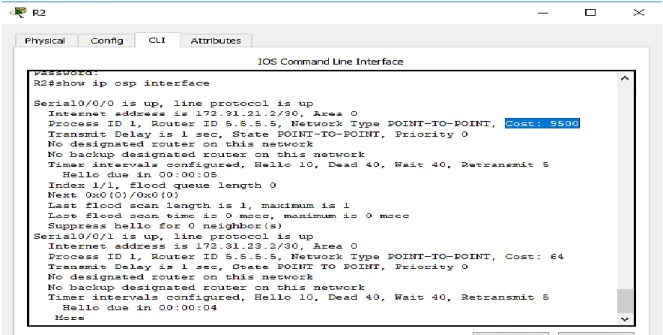
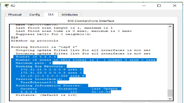
2.2.3 Verificar información de OSPF
2.2.3.1 Visualizar lista resumida de interfaces por OSPF en donde se ilustre el costo de cada interface
30
2.2.3.2 Visualizar el OSPF Process ID, Router ID, Address summarizations, Routing Networks, and passive interfaces configuradas en cada router
Ilustración 7. OSPF procesos
2.2.4. Configurar VLANs, Puertos troncales, puertos de acceso, encapsulamiento, Inter - VLAN Routing y Seguridad en los Switches acorde a la topología de red establecida.
En este paso se especifican los puertos troncales.
2.2.4.1 Configuración en S1:
S1#conf t
Enter configuration commands, one per line. End with CNTL/Z. S1(config)#vlan 30
S1(config-vlan)#name Administracion S1(config-vlan)#vlan 40
31 S1(config-vlan)#vlan 200
S1(config-vlan)#name Mantenimiento
S1(config-vlan)#exit S1(config)#
S1(config)#vlan 30
S1(config-vlan)#name Administracion
S1(config-vlan)#vlan 40
S1(config-vlan)#name mercadeo S1(config-vlan)#vlan 200
S1(config-vlan)#name Mantenimiento S1(config-vlan)#exit
S1(config)#int vlan 200
S1(config-if)#
%LINK-5-CHANGED: Interface Vlan200, changed state to up
S1(config-if)#int vlan 200
S1(config-if)#ip address 192.168.99.2 255.255.255.0 S1(config-if)#no shutdown
S1(config-if)#exit
S1(config)#ip default-gateway 192.168.99.1 S1(config)#int f0/3
S1(config-if)#switchport mode trunk S1(config-if)#
%LINEPROTO-5-UPDOWN: Line protocol on Interface FastEthernet0/3, changed state to down
32
%LINEPROTO-5-UPDOWN: Line protocol on Interface Vlan200, changed state to up
S1(config-if)#switchport trunk native vlan 1
S1(config-if)#int f0/24
S1(config-if)#switchport mode trunk
S1(config-if)#switchport trunk native vlan 1
S1(config-if)#int range fa0/2, fa0/4-23, g0/1-2 S1(config-if-range)#swtch mode access S1(config-if-range)#switch mode access
S1(config-if-range)#int fa0/1 S1(config-if)#switch mode access
S1(config-if)#switch access vlan % Incomplete command.
S1(config-if)#switch access vlan 30
S1(config-if)#int range fa0/2, fa0/4-23, g0/1-2 S1(config-if-range)#shutdown
%LINK-5-CHANGED: Interface FastEthernet0/2, changed state to administratively down
%LINK-5-CHANGED: Interface FastEthernet0/4, changed state to administratively down
%LINK-5-CHANGED: Interface FastEthernet0/5, changed state to administratively down
%LINK-5-CHANGED: Interface FastEthernet0/6, changed state to administratively down
%LINK-5-CHANGED: Interface FastEthernet0/7, changed state to administratively down
33
%LINK-5-CHANGED: Interface FastEthernet0/9, changed state to administratively down
%LINK-5-CHANGED: Interface FastEthernet0/10, changed state to
administratively down
%LINK-5-CHANGED: Interface FastEthernet0/11, changed state to
administratively down
%LINK-5-CHANGED: Interface FastEthernet0/12, changed state to
administratively down
%LINK-5-CHANGED: Interface FastEthernet0/13, changed state to
administratively down
%LINK-5-CHANGED: Interface FastEthernet0/14, changed state to
administratively down
%LINK-5-CHANGED: Interface FastEthernet0/15, changed state to
administratively down
%LINK-5-CHANGED: Interface FastEthernet0/16, changed state to
administratively down
%LINK-5-CHANGED: Interface FastEthernet0/17, changed state to
administratively down
%LINK-5-CHANGED: Interface FastEthernet0/18, changed state to
administratively down
%LINK-5-CHANGED: Interface FastEthernet0/19, changed state to
administratively down
%LINK-5-CHANGED: Interface FastEthernet0/20, changed state to
administratively down
%LINK-5-CHANGED: Interface FastEthernet0/21, changed state to
administratively down
%LINK-5-CHANGED: Interface FastEthernet0/22, changed state to
administratively down
%LINK-5-CHANGED: Interface FastEthernet0/23, changed state to
34
%LINK-5-CHANGED: Interface GigabitEthernet0/1, changed state to
administratively down
%LINK-5-CHANGED: Interface GigabitEthernet0/2, changed state to
administratively down S1(config-if-range)#
2.2.4.2 Configuración en S2:
Switch(config)#vlan 30
Switch(config-vlan)#name Administracion Switch(config-vlan)#vlan 40
Switch(config-vlan)#name mercadeo Switch(config-vlan)#vlan 200
Switch(config-vlan)#name Mantenimiento
Switch(config-vlan)#exit Switch(config)#int vlan 200 Switch(config-if)#
%LINK-5-CHANGED: Interface Vlan200, changed state to up
%LINEPROTO-5-UPDOWN: Line protocol on Interface Vlan200, changed state to up
Switch(config-if)#ip address 192.168.99.3 255.255.255.0 Switch(config-if)#no shut
Switch(config-if)#exit
35 2.2.4.3 Configuración en R1:
R1(config-subif)#encapsulation dot1q 30
R1(config-subif)#ip address 192.168.30.1 255.255.255.0 R1(config-subif)#int f0/1.40
R1(config-subif)#encapsulation dot1q 40
R1(config-subif)#ip address 192.168.40.1 255.255.255.0 R1(config-subif)#int f0/1.200
R1(config-subif)#encapsulation dot1q 200
R1(config-subif)#ip address 192.168.200.1 255.255.255.0 R1(config-subif)#exit
R1(config)#
2.2.4.4 Configurar en R1 la conexión hacia R2:
R1(config)#int s0/0/0
R1(config-if)#description Connetion to R2
R1(config-if)#ip address 172.31.21.1 255.255.255.252 R1(config-if)#clock rate 128000
This command applies only to DCE interfaces R1(config-if)#no shutdown
R1(config-if)#ip route 0.0.0.0 0.0.0.0 s0/0/0 R1(config)#
2.2.4.5 Configuración en R2:
R2(config)#int s0/0/1
36
R2(config-if)#ip address 172.31.21.2 255.255.255.252 % 172.31.21.0 overlaps with Serial0/0/0
R2(config-if)#ip address 172.31.21.2 255.255.255.252 % 172.31.21.0 overlaps with Serial0/0/0
R2(config-if)#no shutdown R2(config-if)#int s0/0/0
R2(config-if)#description connection to R3
R2(config-if)#ip address 172.31.23.1 255.255.255.252 % 172.31.23.0 overlaps with Serial0/0/1
R2(config-if)#int f0/0
R2(config-if)#ip address 209.165.200.225 255.255.255.248 R2(config-if)#no shutdown
R2(config-if)#exit R2(config)#int f0/1
R2(config-if)#ip address 10.10.10.10 255.255.255.0 R2(config-if)#no shutdown
R2(config-if)#
%LINK-5-CHANGED: Interface FastEthernet0/1, changed state to up
%LINEPROTO-5-UPDOWN: Line protocol on Interface FastEthernet0/1, changed state to up
37 2.2.4.6 Configuración en R3:
R3>en Password: R3#conf t
Enter configuration commands, one per line. End with CNTL/Z. R3(config)#int s0/0/1
R3(config-if)#description connection to R1
R3(config-if)#ip address 172.31.23.2 255.255.255.252 R3(config-if)#no shutdown
R3(config-if)#
R3(config)#int s0/0/1
R3(config-if)#description connection to R1
R3(config-if)#ip address 172.31.23.2 255.255.255.252
R3(config-if)#no shutdown R3(config-if)#int lo4
R3(config-if)#ip address 192.168.4.1 255.255.255.0
R3(config-if)#int lo4
R3(config-if)#ip address 192.168.4.1 255.255.255.0 R3(config-if)#int lo5
R3(config-if)#ip address 192.168.5.1 255.255.255.0 R3(config-if)#no shutdown
R3(config-if)#int lo6
38
2.2.5 En el Switch 3 deshabilitar DNS LOOKUP
S2#conf t
Enter configuration commands, one per line. End with CNTL/Z. S2(config)#no ip domain-lookup
S2(config)#
2.2.6 Asignar direcciones IP a los Switches acorde a los lineamientos
En S1:
S1(config)#int f0/3
S1(config-if)#exit S1(config)#int vlan 99
S1(config-if)#ip address 192.168.99.2 255.255.255.0
S1(config-if)#no shutdown S1(config-if)#
En S2:
S2>en
S2#conf t
Enter configuration commands, one per line. End with CNTL/Z. S2(config)#int vlan 99
39 S2(config-if)#no shutdown
S2(config-if)#
2.2.7 Desactivar todas las interfaces que no sean utilizadas en el esquema de red
En S1:
S1(config)#int range fa0/2-24 S1(config-if-range)#sh
%LINK-5-CHANGED: Interface FastEthernet0/24, changed state to
administratively down
S1(config-if-range)#
%LINK-5-CHANGED: Interface FastEthernet0/3, changed state to administratively down
%LINEPROTO-5-UPDOWN: Line protocol on Interface FastEthernet0/3, changed state to down
%LINEPROTO-5-UPDOWN: Line protocol on Interface Vlan200, changed state to down
En S2:
S2(config-if)#int range fa0/2-24 S2(config-if-range)#shutdown
%LINK-5-CHANGED: Interface FastEthernet0/2, changed state to administratively down
40
%LINK-5-CHANGED: Interface FastEthernet0/4, changed state to administratively down
%LINK-5-CHANGED: Interface FastEthernet0/5, changed state to administratively down
%LINK-5-CHANGED: Interface FastEthernet0/6, changed state to administratively down
%LINK-5-CHANGED: Interface FastEthernet0/7, changed state to administratively down
%LINK-5-CHANGED: Interface FastEthernet0/8, changed state to administratively down
%LINK-5-CHANGED: Interface FastEthernet0/9, changed state to administratively down
%LINK-5-CHANGED: Interface FastEthernet0/10, changed state to
administratively down
%LINK-5-CHANGED: Interface FastEthernet0/11, changed state to
administratively down
%LINK-5-CHANGED: Interface FastEthernet0/12, changed state to
administratively down
%LINK-5-CHANGED: Interface FastEthernet0/13, changed state to
administratively down
%LINK-5-CHANGED: Interface FastEthernet0/14, changed state to
administratively down
%LINK-5-CHANGED: Interface FastEthernet0/15, changed state to
administratively down
%LINK-5-CHANGED: Interface FastEthernet0/16, changed state to
administratively down
%LINK-5-CHANGED: Interface FastEthernet0/17, changed state to
administratively down
%LINK-5-CHANGED: Interface FastEthernet0/18, changed state to
41
%LINK-5-CHANGED: Interface FastEthernet0/19, changed state to
administratively down
%LINK-5-CHANGED: Interface FastEthernet0/20, changed state to
administratively down
%LINK-5-CHANGED: Interface FastEthernet0/21, changed state to
administratively down
%LINK-5-CHANGED: Interface FastEthernet0/22, changed state to
administratively down
%LINK-5-CHANGED: Interface FastEthernet0/23, changed state to
administratively down
%LINK-5-CHANGED: Interface FastEthernet0/24, changed state to
administratively down
S2(config-if-range)#
2.2.8 Implemente DHCP and NAT for IPV4
R1(config)#Ip dhcp excluded-address 192.168.30.1 192.168.30.30 R1(config)#Ip dhcp excluded-address 192.168.40.1 192.168.40.30 R1(config)#
2.2.9 Configurar R1 como servidor DHCP para las VLANs 30 y 40
Se reservan las 30 direcciones iniciales, se nombra un pool para cada vlan
42
Enter configuration commands, one per line. End with CNTL/Z. R1(config)#ip dhcp excluded-address 192.168.30.1 192.168.30.30
R1(config)#ip dhcp excluded-address 192.168.40.1 192.168.40.30 R1(config)#ip dhcp pool admin
R1(dhcp-config)#dns-server 10.10.10.11 R1(dhcp-config)#default-router 192.168.30.1
R1(dhcp-config)#network 192.168.30.0 255.255.255.0 R1(dhcp-config)#ip dhcp pool merca
R1(dhcp-config)#dns-server 10.10.10.11
R1(dhcp-config)#default-router 192.168.40.1
R1(dhcp-config)#network 192.168.40.0 255.255.255.0 R1(dhcp-config)#
2.2.10 Reservar las primeras 30 direcciones IP de las VLAN 30 y 40 para configuraciones estáticas
2.2.10.1 Configurar DHCP pool para VLAN 30
Name: ADMINISTRACION DNS-Server: 10.10.10.11 Domain-Name: ccna-unad.com Establecer default gateway.
R1#conf t
R1(config)#dhcp exclude-address 192.168.30.1 192.168.30.30 R1(config)#ip dhcp exclude-address 192.168.30.1 192.168.30.30 R1(config)#ip dhcp excluded-address 192.168.30.1 192.168.30.30
43 R1(config)#ip dhcp pool Administracion R1(dhcp-config)#dns-server 10.10.10.11
R1(dhcp-config)#domain-name ccna-unad.com R1(dhcp-config)#ip domain-name ccna-unad.com R1(config)#defo
R1(config)#
2.2.10.2 CONFIGURAR DHCP POOL PARA VLAN 40
Name: MERCADEO DNS-Server: 10.10.10.11 Domain-Name: ccna-unad.com Establecer default gateway.
R1>en Password: R1#conf t
Enter configuration commands, one per line. End with CNTL/Z. R1(config)#ip dhcp poll Mercadeo
R1(config)#ip dhcp pool Mercadeo
R1(dhcp-config)#dns-server 10.10.10.11
R1(dhcp-config)#ip domain-name ccna-unad.com R1(config)#ip dhcp pool Mercadeo
R1(dhcp-config)#default-router 192.168.40.1
44
2.2.11 Configurar NAT en R2 para permitir que los hosts puedan salir a internet
R2>en Password: R2#conf t
Enter configuration commands, one per line. End with CNTL/Z. R2(config)#ip nat in
% Incomplete command.
R2(config)#ip nat inside source static 10.10.10.10 209.165.200.224 R2(config)#interface f0/0
R2(config-if)#ip nat outside f0/1
R2(config-if)#ip nat outside R2(config-if)#interface f0/1 R2(config-if)#ip nat inside
R2(config-if)#exit
R2(config)#interface f0/0 R2(config-if)#ip nat outside
R2(config-if)#interface f0/1 R2(config-if)#ip nat inside R2(config-if)#exit
45
2.2.12 Configurar al menos dos listas de acceso de tipo estándar a su criterio en para restringir o permitir tráfico desde R1 o R3 hacia R2.
R2(config)#access-list 1 permit 192.168.30.0 0.0.0.255 R2(config)#access-list 1 permit 192.168.40.0 0.0.0.255 R2(config)#access-list 1 permit 192.168.4.0 0.0.3.255
R2(config)#
2.2.13 Configurar al menos dos listas de acceso de tipo extendido o nombradas a su criterio en para restringir o permitir tráfico desde R1 o R3 hacia R2
R1>en Password: R1#conf t
Enter configuration commands, one per line. End with CNTL/Z.
R1(config)#access-list 120 permit udp any host 192.168.40.31 eq domain R1(config)#access-list 120 permit tcp any host 192.168.40.31 eq domain
46
2.2.14 Verificar procesos de comunicación y redireccionamiento de tráfico en los routers mediante el uso de Ping y Traceroute
48 Ilustración 10. Comando ping en Internet PC.
49
CONCLUSION
De la anterior actividad práctica se puede concluir:
Con la gestión del protocolo DHCP se busca el dinamismo en cuanto al tiempo empleado cuando se trata de redes extensas
OSPF es un protocolo cuyo rendimiento mejora en redes diversas que tienen gran extensión.
OSPF divide la red en areas para optimizar el tráfico de direccionamiento que se genera.
50
REFERENTES BILBIOGRÁFICOS
CISCO. (2014). OSPF de una sola área. Principios de Enrutamiento y
Conmutación. Recuperado de
https://static-course-assets.s3.amazonaws.com/RSE50ES/module8/index.html#8.0.1.1
CISCO. (2014). DHCP. Principios de Enrutamiento y Conmutación. Recuperado
de