Imaging system applications of multichannel configuration
Jose M. Infante Herrero1 ,Juan Carlos Miñano Dominguez 1,2, Pablo Benítez 1,2; Guillermo Biot 1, Hammed Ahmadpanahi 1, Wang Lin 1 ,Liu JiaYao1,Julio C Chaves2 ,Marta C. de la Fuente3,
1Universidad Politécnica de Madrid, CeDInt, Campus Montegancedo, 28223 Madrid, Spain; 2Light Prescriptions Innovators-Europe, Edif.
CeDInt Campus Montegancedo UPM, 28223 Pozuelo, Madrid, Spain, 3Indra Sistemas SA, Joaquín Rodrigo 11, 28300 Aranjuez,
jose.infante@cedint.upm.es
ABSTRACT
While multichannel configurations are well established for non-imaging applications, they have not been used yet for imaging applications. In this paper we present for the first time some of multichannel designs for imaging systems. The multichannel comprises discontinuous optical sections which are called channels. The phase-space representation of the bundle of rays going from the object to the image is discontinuous between channels. This phase-space ray-bundle flow is divided in as many paths as channels there are but it is a single wavefront both at the source and the target. Typically, these multichannel systems are at least formed by three optical surfaces: two of them have discontinuities (either in the shape or in the shape derivative) while the last is a smooth one. Optical surfaces discontinuities cause at the phase space the wave front split in separate paths. The number of discontinuities is the same in the two first surfaces: Each channel is defined by the smooth surfaces in between discontinuities, so the surfaces forming each separate channel are all smooth. Aplanatic multichannel designs are also shown and used to explain the design procedure.
Keywords: Multichannel configuration, aplanatic system, SMS design
1. INTRODUCTION
The multichannel configuration was designed in the first place for illumination. Because of their small size and hemispheric emission, LEDs are more suitable for compact optics. The approach to designing very thin concentrators/collimators has not always been the same. All approaches have in common the idea of dividing the light flow into different “channels”, each one of them having its own optics with surfaces that are not shared with neighboring channels. Ten years ago, multichannel devices called Stepped Flow-line Optics (SFL) were developed [1], [3]. Designed with the flow-line method [4], they rapidly found applications in backlights [5], [6] and for combining light sources or efficiently distributing light to several locations [7]-[11]. The main disadvantage of these devices lies in their poor manufacturability, due to the flow-line mirrors having deep and complex shapes with much larger lateral area than aperture area.
The purpose of this paper is to show the procedure for designing multichannel systems for imaging systems. The color correction and the diffraction effects won’t be considered, and we will focus on the study of the design method and the possibilities of these kinds of configurations.
2. DESIGN OF THE MULTICHANNEL SYTEM
In this case, since the surface lis flat, all that is necessary is a straight extension of the flow-lines at the output. In this way, the irradiance (flow per unit of surface) on both supporting surfaces will be the same. This requirement is established to avoid discontinuities on the line l, in order to simplify manufacturing.
Fig 1. Design of the distributor d. The optical system to design is bounded by lines l and m.
Fig 2. The distributor ensures that the average irradiance on the supporting surface m is equal to that on the supporting surface l.
Once the distributor is known, a refractive and reflective surface can be designed according to two conditions. In the next section we will study the different conditions that we can apply to these surfaces in order to obtain designs for different applications.
3. APLANATIC DESIGN
Aplanatic systems are asymmetric optical designs free from on-axis spherical aberration and linear coma. These two conditions entail two further design conditions: (1) stigmatic on-axis image and (2) the Abbe sine condition (note that all the rays involved in these conditions are exclusively tangential). The opposite is also true: a design forming a stigmatic on-axis image and fulfilling the Abbe sine condition is aplanatic. Aplanatic designs have long been known through the work of Schwarzschild [19], Wassermann and Wolf [20], Welford [21], Mertz [22], [23] and others. Recently Lynden-Bell and Willstrop derived an analytic expression of more general aplanats [24], [25]. The Abbe sine condition can be derived from the condition of zero linear coma, but this is just one possible approach. For instance, Clausius, who derived the Abbe condition in 1864, did it from thermodynamic arguments [21] (we can also say that he used the conservation of etendue theorem [2]). In 1884, Hockin provided proof using path differences along tangential rays [21].
Aplanatic designs are particular cases of two-surface SMS 2D designs [4], [12]-[18]. An SMS design is a more general case, which in its simpler version can form a stigmatic image of two off-axis points. When these two points of the (two surface) SMS design is at an infinitesimal distance apart around the axis, the SMS design becomes an aplanatic design [14].
aplanatic systems with a continuous optical surface (that supported by l) in which the incident wavefronts are separated, individually focused, and rebuilt in different optical channels that operate in parallel.
As we explained before, the first part of the design is the design of the distributor. Depending on the application that we are looking for, the distributor has to fulfill the Abbe-sine condition. That Abbe sine condition is given by:
(1)
Here n and n’ are the indexes of refraction of the materials where the object and the image are immersed, θ is the angle of the ray coming from the object with the optical axis, and α in the angle in the image.
If the object is in the infinity and the image is not immersed in a material, the Abbe condition is given by
(2)
Here x is the height of the ray entering into the optical system, f the focal length and α is the angle of this ray with the optical axis in the image.
Using (2) we can design a multichannel configuration for an objective. We will assume a wavelength of 586 nm and a refractive index of 1.5. The focal length of the objective is 800 mm.
Fig 3. The distributor is designed in such a way that the rays coming from the image after the reflection on it find line m at a point with coordinate x=fsinθ.
After design of the distributor, we have to design each channel. Note that each channel is composed of two surfaces. Theses surfaces are calculated using the Abbe sine condition and the constant optical path length. Aplanatic design of the channels is calculated with different optical path lengths so that their refractive surfaces are continuous.
Fig 4. Aplanatic design of the objective.
It must be considered that the aplanatic design only gives us good image quality on axis. In order to obtain good image quality for more than a wavefront, the SMS method can be used or an optimization process can be applied. In the next section, we will show an example where an optimization process was applied.
4. EXAMPLES
are used in a wide range of applications such as power changers in microscopes, FLIR systems, laser beam expanders, etc.
In this section we are going to show a couple of monochromatic examples. The first one is a 6.5x telescope, located in front of a CCD camera with 122.4 mm of focal length, F/11.2 and ±0.85º of field of view.
For the afocal design we have used a similar method. The difference is the condition that the distributor as well as the two surfaces must fulfill. That condition is given by the magnification expression of the pupils:
(3)
Here x’ is the coordinate of the ray in the exit pupil and x the coordinate of the ray in the entrance pupil and M is the magnification. The design of the 6.5x telescope it shown in fig (5).
Fig 5. 6.5x Multichannel telescope.
For this example we have used BK7 as material and we have assumed a wavelength of 587 nm. To design this system we started using the aplanatic design. Afterwards we optimized it in order to minimize the angular error for each field of view
There are different ways to study the behavior of the afocal system; some computer programs simply use a very large image distance for ray tracing evaluation, while others use a “perfect lens” at the exit pupil. In this case we will evaluate the behavior of the afocal system using a “perfect lens” of 795.6 mm of focal length obtaining the following results:
Fig 6. Geometrical spot diagram versus field of view .The FOV is the FOV in the entrance pupil and RMS is diameter of the spot obtained in the image of the perfect lens.
Taking into account that the physical diameter of the Airy disc is given by:
(3)
we obtained diffraction spot of ~ 16 μm. Because of this fact we can relax the image quality on axis and focus the optimization in order to obtain the best image quality off axis, obtaining the red curve on the figure 6, where we notice that almost all the FOV of the camera is diffraction-limited.
The aplanatic design works well for laser beam expander applications, first because the color correction of the laser-based optical system is much easier due to the fact the wavelength band of the laser is extremely narrow, and secondly because laser systems are often corrected for small fields of view and this is quite suitable for aplanatic design.
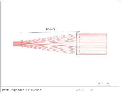
In this case we are going to compare an academic example of a laser beam expander 4x given in [26] with the multichannel configuration of a beam expander of 4x. The academic design is shown in the following figure:
Fig 6. Academic design of beam expander 4x.
In this design a wavelength of 600 nm and a refractive index of 1.52 were assumed. The multichannel configuration is completely suitable for this kind of configuration. For this design we decided to introduce some variations in relation to the previous designs. Instead of designing all the systems in a certain material, we decided to use a thin refractive element and two mirrors.
In the previous designs, we have presented configurations with obscurations. In order to avoid this we decided to design only half of the distributor. Note that the procedure is the same as with the previous afocal design. The only difference is that the entrance pupil is decentered, obtaining the following design:
Fig 7. Multichannel design of beam expander 4x with 12.5 mm of length.
The results obtained for this design can be shown in figure 8 where we present ray trace curves. In these ray trace curves the abscissa is the normalized exit pupil radius in the y direction, and the ordinate is the error between the theoretical angle of incident for this ray in exit pupil, and the real angle of incident.
Note that this is an alternative way to study the behavior of the rays for focal systems, similar to the ray trace curves for focal systems where the ordinate is the distance above or below the chief ray on the image that the rays intercept on the image plane.
(a)
(b)
Fig 8. Ray trace curves for the multichannel beam expander 4x (a) on axis, (b) 0.1 degree in the object space.
The results obtained for this example have been obtained without any optimization. Note that even if the real usable field of view of the beam expander is zero, the system must be designed over a small field of view in order to accommodate the assembly and the alignment tolerances.
5. CONCLUSIONS
We have presented a procedure to design thin optical systems, in particular an objective and a couple of examples of afocal systems. The designs contain a distributor element that makes the design thin. The remaining optical elements are grouped in channels which are designed independently to the other ones. Depending on the conditions the multichannel can be used for different applications. Two afocal systems were shown as examples: a telescope 6.5x which was optimized in order to obtain a good image quality for all the field of view considered, and a beam expander 4x. The beam expander configuration gave us an idea that the compactness of the multichannel configuration.
The results obtained for a monochromatic system show that the multichannel configuration can be a possibility in order to perform very thin optical imaging systems. The color correction of these systems needs to consider one condition more over the construction of the channels. This new condition will vary the design procedure a bit. For this reason the color correction and the considerations for the manufacturability shall be presented in a future work.
6. ACKNOWLEDGEMENT
The LPI’s devices and designs presented in this paper are protected under US and International patents pending by LPI LLC, 2400 Lincoln Avenue, Altadena, CA 91001 USA http://www.lpi-llc.com/.Authors thank the Spanish Ministries, (SEM: TSI-020302-2010-65) and the Madrid Regional Government (SPIR: 50/2010O.23/12/09,TIC2010 and O-PRO: PIE/209/2010) and UPM (Q090935C59) for the support given in the preparation of the present work. The authors also thank to Synopsys (formerly Optical Research Associates) customer service for all the help.
REFERENCES
[1] Chaves, J., Collares-Pereira, M., “Ultra flat ideal concentrators of high concentration”, Solar Energy, 69, 269-,(2000).
[2] Chaves, J., Collares-Pereira, M., “Ideal concentrators with gaps”, Appl. Opt., 41, 1267-, (2002). [3] Chaves, J., [Introduction to Nonimaging Optics], CRC Press, (2008).
[4] Winston, R., Miñano, J.C., Benítez, P., [Nonimaging Optics], Academic Press, New York, (2005). [5] Miñano, J.C., Benítez, P., Chaves, J., Falicoff, W., Parkyn, W., “Etendue-conserving illumination-optics forbacklights and frontlights”, US patent application
[6] Miñano, J.C., Benítez, P., Chaves, J., Hernandez, M., Dross, O. and Santamaria, A., “High-efficiency LED backlight optics designed with the flow-line method”, Proc. SPIE 5942, (2005).
[7] Chaves, J., Falicoff, W., Miñano, J.C., Benítez, P., Parkyn, W., Alvarez, R., Dross, O., “Optical manifold forlight-emitting diodes”, United States Patent 7380962
[8] Chaves, J., Falicoff, W., Dross, O., Miñano, J.C., Benítez, P., Parkyn, W., “Combination of light sources andlight distribution using manifold optics”, Proc. SPIE 6338, (2006).
[9] Cvetkovic, A., Dross, O., Chaves, J., Benítez, P., Miñano, J.C., and Mohedano, R., “Etendue-preserving mixing and projection optics for high-luminance LEDs, applied to automotive headlamps”, Optics Express, 14 (26),13014-13020 (2006).
[10] Dross, O., Miñano, J.C., Benítez, P., Cvetkovic, A., Chaves, J., “Non-imaging optics combine LEDs into one bright source”, SPIE Newsroom, http://newsroom.spie.org/x3596.xml (2006).
[11] Dross, O., Cvetkovic, A., Chaves, J., Benítez, P., Miñano, J.C., “LED Headlight Architecture that creates a High Quality Beam Pattern independent of LED Shortcomings”, Proc. SPIE 5942, 126-135 (2005).
[12] Miñano, J.C., González, J.C., "New method of design of nonimaging concentrators", Appl. Opt. 31, 3051-3060 (1992).
[13] Miñano, J.C., Benítez, P., Wang-Lin,, Muñoz, F., Infante, J., Santamaría, A., “Overview of the SMS design method applied to imaging optics”, Proc. SPIE 7429, 74290C (2009).
[14] Benítez, P., Miñano, J.C., "Ultra high-numerical-aperture imaging concentrator," J. Opt. Soc. Am. A 14, 1988-1997 (1988-1997).
[16] Miñano, J.C., Benítez, P., Wang-Lin,, Infante, J., Muñoz, F., Santamaría, A., "An application of the SMS method for imaging designs," Opt. Express 17, 24036-24044 (2009).
[17] Luneburg, R. K., [Mathematical Theory of Optics], University of California Press, Berkeley, (1964). [18] Stravoudis, O.N., [The Optics of Rays, Wavefronts and Caustics], Academic Press, New York, (1972). [19] Schwarzschild, K., "Astronomische Mitteilungen der Königlichen Sternwarte zu Göttingen 10, 3 (1905) ", Reprinted: Selected Papers on Astronomical Optics SPIE Milestone Ser. 73(3), (1993).
[20] Wassermann, G. D. and Wolf, E., “On the Theory of Aplanatic Aspheric Systems,” Proc. Phys. Soc. B 62, 2-8 (1949).
[21] Welford, W.T., “Aplanatism and Isoplanatism,” Progress in Optics 13, 267-293 (1976).
[22] Mertz, L., “Geometrical design for aspheric reflecting surfaces,” Appl. Opt. 18, 4182-4186 (1979). [23] Mertz, L., “Aspheric potpourri,” Appl. Opt. 20, 1127-1131 (1981).
[24] Lynden-Bell, D., “Exact Optics: A Unification of Optical Telescope Design,” MNRAS 334, 787-796 (2002). [25] Willstrop, R.V., Lynden-Bell, D., “Exact Optics — II. Exploration of Designs On- and Off-Axis,” MNRAS 342, 33-49 (2003).