Status of CIEMAT Contribution to Future Colliders
Luis García-Tabarés on Behalf of CIEMAT
XIII Jornadas de Futuros Colisionadores Lineales Zaragoza, 26 de Enero de 2017
CIEMAT & Future Particle Accelerators
1) RESOURCES Div. Basic Research Div. Fusion Div. Technology
&
ACTIVITIES Physics & Detectors Fusion Accelerators Large Facilities & Med. Accel
SC MAGNETS RESISTIVE
MAGNETS SPECIAL
MAGNETS NON-SC
RF INSTRU-
MENTATION
E-XFEL XXX XX XXX
ILC X
CLIC XX XXX XXX XXX
HL-LHC XXX
HE-LHC XXX
FCC XXX
4) RESTRICTIONS: * Group Size * Inability to permanently fix the personnel
* Permanent administrative restrictions to almost any initiative (even daily aspects) * Lack of a technological high-level policy/strategy in large facilities * Submission to MINEICO decisions.
5) PROPOSALS: * Efficient selection of technical contributions * Active participation from industry * Coordinated distribution of contributions among accelerator groups (CONECTA)
2) ACCELERATOR TYPES: LINEAR CIRCULAR
Driving Technology ILC:SC Cavities (No expertise) XX-LHC SC Magnets (Significant expertise) CLIC: Non SC Cavities FCC
3) PROJECTS &
TECHNOLOGIES
(So far developed, or
committed)
CIEMAT Contribution to HL-LHC
7th´HL-LHC Collaboration Board Meeting. MADRID. 13th November 2017
The MCBX Magnet (1)
4
A MCBXFB
Magnet Prototype
CERN & CIEAMT signed a collaboration agreement in 2014 for the development of a MCBXFB prototype in which CIEMAT takes care of the magnet & tooling design and the fabrication of the magnet, while CERN provides the cable, raw material for collars & iron yoke and the facilities for collaring and assembly.
MCBXFB &
MCBXFA Series Production
CERN, CDTI and CIEMAT are in the process of signing an Agreement for the procurement of 1+6 MCBXFA (long) magnets plus another 12 MCBXFB (short) magnets to be installed in the HL-LHC as Spanish In-Kind Contribution to the Project.
MCBXB MCBXA
7th´HL-LHC Collaboration Board Meeting. MADRID. 13th November 2017 5
The MCBX Magnet (2)
MCBXFB Technical specifications Magnet configuration Combined dipole
(Operation in X-Y square) Integrated field 2.5 Tm
Minimum free aperture 150 mm Nominal current < 2500 A Radiation resistance 40 MGy
Physical length < 1.505 m Working temperature 1.9 K
Iron geometry MQXF iron holes Field quality < 10 units (1E-4)
Fringe field < 40 mT (Out of the Cryostat)
Vertical dipole field (2.1 T)
Horizontal dipole field
(2.1 T) Combined dipole field
(Variable orientation)
Cable Parameters No. of strands 18 Strand diameter 0.48 mm Cable thickness 0.845 mm Cable width 4.37 mm Key-stone angle 0.67º
Cu:Sc 1.75
7th´HL-LHC Collaboration Board Meeting. MADRID. 13th November 2017 6
PHASE MILESTONES STATU
S Magnetic, Mechanical &
Quench Calculations
Field Quality
Mechanical Stresses
Voltages & Temperature
DONE
Short Mechanical Models
Coil Mechanical Properties
Collar Assembly Testing
Coil Stress Measurement
DONE
Magnet & Tooling Design
Coil & Magnet Drawings
Winding Tooling
Binder & Impregnation Tooling
• Assembly Tooling
ON GOING Dec 2017
Magnet Components &
Tooling Fabrication
Spacers & End Spacers
• Collars & Iron Yoke
Winding Table, Spools & Brakes
• Binder & Impregnation Tooling
ON GOING May 2018
Coil Fabrication
ID Coil Winding & Binding
ID Coil Curing
• OD Coil Winding & Binding
• OD Coil Curing
ON GOING April 2018
Magnet Assembly
• ID Coil Collaring
• ID+OD Coil Collaring
• Iron Assembly
• End Plates & Connections
NOT STARTED June 2018
The MCBX Magnet (3)
The QUACO project is a part of the IR magnets in the HL-LHC and has as an objective the production of the first two First-of-a-kind HL-LHC “two in one quadrupole magnets (MQYY)”.
Participants:
1) The European Organization for Nuclear Research (CERN),
2) Commissariat A L’Energie Atomique Et Aux Energies Alternatives (CEA),
3) Centro de Investigaciones Energéticas, Medioambientales Y Tecnológicas (CIEMAT), 4) Narodowe Centrum Badan Jadrowych (NCBJ).
It takes the form of a pre-commercial procurement (PCP) which is an approach for purchasing R&D services for the development of innovative services not yet available in the market.
The scope of QUACO is to procure 2 pilot 3,8 m quadrupole magnets (Q4) with two 90 mm aperture, an integrated gradient of 440T with 120T/m in the transverse plane, with operational temperature of 1.9K (it will be installed in the HL-LHC matching sections).
The QUACO Magnet (1)
QUACO Time Schedule
The QUACO Magnet (2 )
CIEMAT Contribution to CLIC
First CIEMAT potential contribution to CLIC:
Design and production of 90 combined function
dipoles with longitudinal variable field for the Damping Rings.
CIEMAT committed contribution to CLIC:
WP2: Construction of a Magnet Prototype
Field provided by permanent magnets
Combined function dipoles: dipolar (bending) and quadrupolar (focusing/defocusing) field
Longitudinal gradient: reduces the horizontal emittance
Four different cases were analyzed: finally the most
complicated and effective one is achieved (Trapezium profile case 1)
Longitudinal Variable Field Dipoles (1)
C-shaped Magnet with gap pointing outwards
SmCo in Low Field Region NdFeB in Medium & High Field Regions Flux concentration
Hyperbolic pole tips profile Armco
Fe-Co (Vacoflux) Flat pole tip profile Passive trimming
Dimensions:
0.65 x 0.68 x 0.56 m Weight: 1.1 T
Longitudinal Variable Field Dipoles (2)
Cavity type Travelling wave Average Accelerating gradient 100 MV/m
Frequency 12 GHz
Phase advance per cell 2π/3
Number of accelerating cells 26
Structure length 230 mm
Aperture 4,8 – 6,2 mm
Peak input power 61,3 MW
Maximum surface electric field 230 MV/m Max. pulsed surface heating
temperature 47 K
The TD26_R1_CC Accelerating Structure (1)
Second CIEMAT potential contribution to CLIC:
Design and production of the Accelerating Structures for the Main Beam.
CIEMAT committed contribution to CLIC:
WP2: Construction of a TD26_R1_CC A Accelerating Structure Prototype.
26 copper discs fabricated with ultra high precision diamond machining, with tolerances at the micron level and roughness of 25 nm.
Auxiliary copper and stainless steel parts (couplers, cooling, beam flanges, etc.)
Core structure joint by diffusion bonding of the discs.
Additional brazing processes for the auxiliary parts
CHARACTERISTICS
The TD26_R1_CC Accelerating Structure (1)
CURRENT STATUS
The 24 Central Copper disks have been fabricated &
measured PENDING ACTIVITIES
Bonding Tests December 2017 (delayed)
Fabrication of the remaining parts June 2018
Assembly, Alignment, Bonding & Brazing December 2018
Characterization Tests March 2019
Tuning & Bakeout July 2019
Final Reporting September 2019
CIEMAT Contribution to FCC
The EuroCirCol Collaboration (1)
CERN has recently launched a feasibility conceptual study for post-LHC particle accelerator options, considering the technology research and development programs that would be required to build a future circular collider in the range of 100 TeV. Among other initiatives, an international collaboration called EuroCirCol has been awarded with a H2020 grant to address the main issues of the future machine.
Spanish Contribution to the EuroCirCol Project (FCC)
WorK
Package WP Description LEADING
PARTICIPANT SPANISH PARTICIPANTS
WP1 Management, Coordination and Implementation CERN --
WP2 Arc Design: Conceptual design of the largest fraction of
the collider ring CEA --
WP3 Design of the experimental insertion regions OXFORD
UNIVERSITY --
WP4 Design of the cryogenic beam vacuum system considering
the enormous synchrotron radiation level ALBA ALBA
CIEMAT WP5 High-Field superconducting magnet design for fields up to
16T CERN CIEMAT
High Field Main Dipoles Conceptual Design
The FCC Project: EuroCirCol (2)
OVERVIEW OF MAGNET DESIGN OPTIONS EuroCirCol-P1-WP5-D5.1 Date: 19/10/2016
Grant Agreement 654305 PUBLIC 14 / 16
6. CONCLUSIONS
The activities performed to produce the first deliverable “overview of magnet design options”
consisted in setting up the tools to perform and support the design work, in exploring different design options, and in keeping a continuous contact in an iterative process between the different parties engaged in this collaboration. This aspect of the work is considered to be extremely important and was a key for the successful scientific result of the activity. The homogeneity of the different studies, and the high quality of the scientific work is the result of a remarkably effective attitude of all parts in sharing information through different channels: regular video-meetings (more than one per month in average) in addition to several meetings in person and a large amount of mail exchanges and telephone discussions, an external review, the attendance to workshops and conferences. In particular during the reference period all tasks of WP5 were represented at the EuroCirCol annual meeting (see http://indico.cern.ch/event/448415), the FCC week (see http://indico.cern.ch/event/438866), the ASC conference (see http://ascinc.org).
For each option, two different stages have been considered (18% and 14% conductor load-line margin).
This choice has opened new directions of coil cross section optimisation, in particular:
1) efficient use of the high field conductor, which can be operated at a higher current density 2) considerable decrease of the conductor amount
3) considerable reduction of the magnet inductance thanks to more compact coils and higher current
The coil cross-sections of the three designs are depicted in Figure 10, both for 18% and 14% margin.
The overview of the magnet design option is now complete and the work to finalize and compare these options for the production of the next deliverable D5.2 (identification of preferred dipole design options and cost estimates) has started.
Figure 10: Overview of the coil cross sections for the three design variants
(from left to right: block-coils, cosine-theta and common-coils). Top is the 18% margin version, bottom the 14% margin.
Block Coil (CEA) Cosine Theta (INFN) Common Coils (CIEMAT)
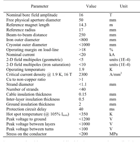
WP5 is devoted to explore different alternatives for the 16T magnets for future Colliders. Three main
options have been launched plus one additional one (Canted Cosine Theta). They are all based on
several common parameters: 50 mm magnet aperture, 2300 A/mm
2current density @16T and
stresses in the coil < 200 MPa at cold.
The Common Coil Solution developed by CIEMAT
The FCC Project: EuroCirCol (3)
2LPo1D-08
Template version 7.2a, 04 August 2016
4 provides a marginal gain, compared to the large strand
diameter. Therefore, to keep a moderate risk on the cable requirement, only the large strand diameter is implemented in the design. Table VII (Design #10) shows the results for these new parameters, which allow additional superconductor saving. In Design #10, if only superconducting strands with copper to superconductor ratio of 1 are used, FCC magnets would need 5737 tons of those strands. The rest could be produced as pure copper strands. It is a possibility under study to reduce costs [8]. Fig. 3 shows the magnetic field map at the conductors.
Detailed simulation of magnet protection was made using custom tools [7] which showed that the peak voltages of Design #10 were well above requirements: 3.2 kV to ground, 100 V between turns and 4.3 kV between layers. An alternative design has been explored using a large current of 15180 A. In this case, peak voltages are smaller (1.4 kV to ground, 80 V between turns and 2 kV between layers) but only the voltage between turns is within requirements. The drawback is the poor efficiency of the superconductor: 10018 tons are necessary for FCC magnets.
It is noticeable that the amount of stored energy is about twice that stored in an equivalent block [3] or cos-theta [4]
dipole. It is because in a common coil magnet there is no shared flux between apertures, so the high field region is larger than in the other configurations. We used a simple model of a common coil dipole with coils represented as rectangular blocks to study the sensitivity of the stored energy with the intra-beam distance: the stored energy was nearly constant for different intra-beam distances. Therefore, the only way to reduce the stored energy is to increase the superconductor efficiency to use smaller coil blocks. In that sense, we plan to include internal grading in the medium field coil or use more complicated ancillary coils [9]. A large amount of stored energy is a problem for FCC operation, since bending magnets are powered in series. Additionally, we plan to study the use of cold diodes to balance the voltages between the coils and reduce the peak voltages during quench.
Finally, it is worth to notice that the intra-beam distance can be noticeably reduced in the case of a compact design. For instance, Design #10 can be modeled with 280 mm separation between the apertures. If they are placed closer, the problems reported in Section IV.A arise again.
VII. CONCLUSION
This paper shows the ongoing optimization of a 16 T dipole in common coil configuration to be used as FCC bending magnet. In parallel, cos-theta and block layout are being studied using the same input parameters and computing tools for comparison. The main objective is to save superconductor.
We have analyzed the influence of different features (strand diameter, iron size, nominal current, number of coils, internal grading, ancillary coils) to find an optimal. The superconductor volume is reasonable, but some problems are still to be solved, mainly the peak voltages during quench.
Mechanical analysis has been recently started.
ACKNOWLEDGMENT
The authors would like to thank R. Gupta (BNL) and Q. Xu (IHEP) for fruitful discussions on the challenges of a high field common coil dipole. The authors want also to thank B.
Auchmann (PSI) for helpful suggestions to improve the Roxie optimization.
REFERENCES
[1] Horizon 2020 EuroCirCol Consortium Agreement, number 654305.
[2] D. Tommasini, et al., “The 16 T dipole development program for FCC”, this Conference.
[3] C. Lorin, M. Durante, M. Segreti, EuroCirCol “16 T block-coils dipole option for the Future Circular Collider”, IEEE Trans. Appl. Supercond.,
submitted for publication.
Fig. 3. Magnetic field at the cables for Design #10, with ancillary coils and a safety margin of 14% on load line.
Fig. 2. Magnetic field at the iron for Design #9. Return turns of upper ancillary coil are at the outer iron diameter. Return turns of lower ancillary coil are at the non-shown aperture.
Other CIEMAT Contributions
The FTECs Program
This programme is aimed at recent graduates from university or higher technical institutes seeking further training in a wide area of projects. Selected trainees will join a team working at CERN and have the opportunity to enlarge their knowledge through participation in the Hi-Tech activities of the laboratory, in fields such superconducting and resistive magnets, power converters and their associated electronics, cryogenics and vacuum technologies and electronics for detectors, including radiation resistance issues, and related activities on infrastructures with a potential industrial return.
The FTEC (Formacion en las TEcnologias del CERN) Trainee Programme has
been established through a bilateral agreement between CERN and CIEMAT
with the contribution of the SEIDI from the Ministerio de Economía y
Competitividad, as well as the CDTI.
7th´HL-LHC Collaboration Board Meeting. MADRID. 13th November 2017 20
Our Future Plans on Accelerator Technologies
PRISMAC: A CIEMAT-CDTI Collaboration Program for Research on High Field Magnets, Supported by SEIDI & CERN
HL-LHC
MCBX Magnets In-Kind
Contribution
•Training & Support on magnets and facilities
•Use of Facilities during the set-up of CIEMAT Laboratory
•Qualification of CIEMAT as a Technological Partner
• Providing a team, facilities and economical resources to all the activities
• Prototype Development
• Technology Transfer to Industry
• Series Fabrication Follow-up
• Qualification of Industry as
Industrial Partners
• Management of IK contribution to CERN
•Project Funding
•Industrial
exploitation of the associated
technologies (Early Alert)
•Dissemination of the developed technologies to other fields (i.e.
Space. Fusion, Light Sources, Energy..)
•Funding the series production,
components and new personnel
•Supporting the Spanish
Traineeship Program (FTEC)
• Supporting the R&D Program on Key Technologies
Facility for very high field
superconducting magnet prototypes
Development of FCC magnet prototypes
SECRETARIA DE ESTADO DE INVESTIGACION DESARROLLO E INNOVACION
21
Thank you for your attention