Hot rolling mills usually consist of the following process steps: conditioning of the input (sharpening, grinding); heating to rolling temperature; descaling; rolling (roughing including width reduction, rolling to final dimension and properties) and finishing (pruning, cutting, cutting). In 1994, Germany produced about 35% of the sliver, with 1.9 million tons, followed by Italy and France each with a production of 0.9 million tons.
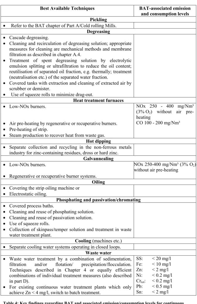
Part B: Continuous Hot Dip Coating
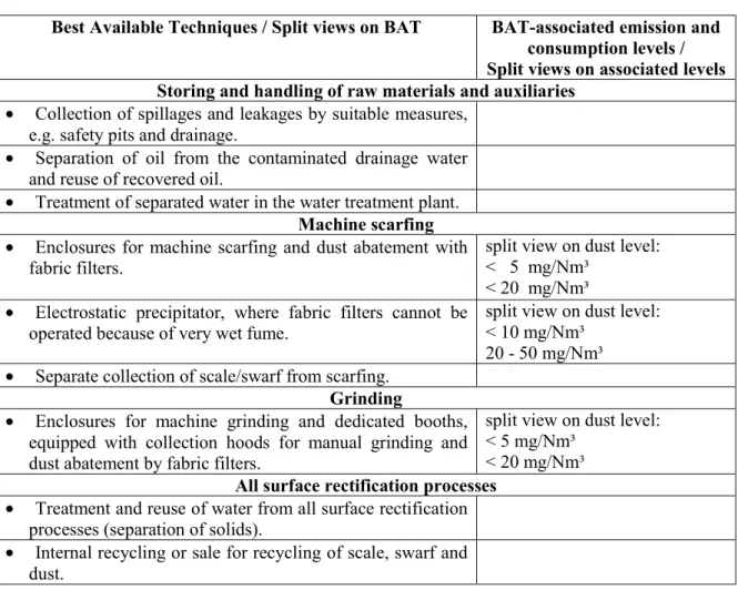
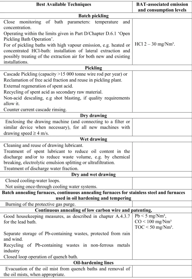
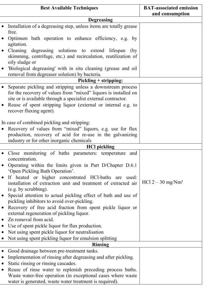
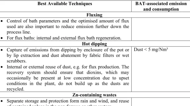
There was consensus in the TWG on the best available techniques and associated emission/consumption levels presented in the table. Waste water-free operation (in exceptional cases where waste water is generated, waste water treatment is required).
PREFACE
- Status of this document
- Objective of this Document
- Information Sources
- How to understand and use this document
In addition, Annex IV of the Directive contains a list of “considerations to be taken into account in general or in specific cases when determining best available techniques. In all circumstances, the terms of the permit must include provisions to minimize long-range or transboundary pollution and ensure a high level of protection of the environment as a whole.
Scope
Ferrous Metals Processing
PART A
Hot and Cold Forming
GENERAL INFORMATION ON HOT AND COLD FORMING
The hot and cold part of the ferrous metal processing sector includes various manufacturing methods such as hot rolling, cold rolling and drawing of steel. It is difficult to compile general information about the sector, statistical data (productivity, number/size of plants, distribution, etc.) and economic information, as most of the available data sources use different bases and different breakdowns of the sector, making it impossible to compare the given data.
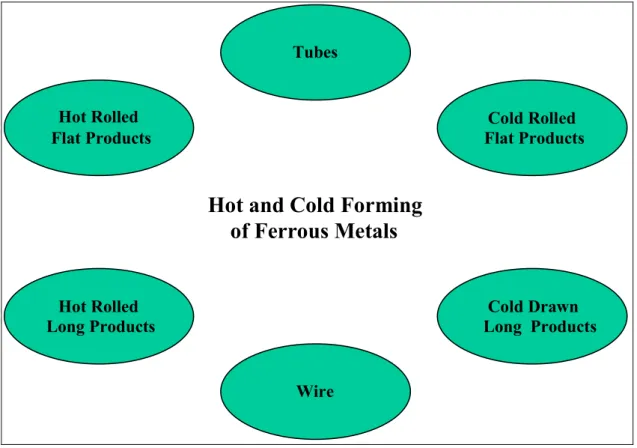
Hot and Cold Forming of Ferrous Metals
- Hot Rolled Flat Products
- Hot Rolled Long Products
- Tubes
- Cold Rolled Flat Products
- Cold Drawn Long Products/ Bright Steel Bars
- Wire
- APPLIED PROCESSES AND TECHNIQUES IN HOT AND COLD FORMING
- Hot Rolling Mills
In terms of total HR housing production, Germany is the largest producer with more than twice the output of downstream producers (France, Belgium, Italy and the UK). About two-thirds of all narrow strip needs in the EU are produced by slitting wide sheet.
![Table A.1-1: Production of Flat Products in EU 15 in 1996 [Stat97]](https://thumb-us.123doks.com/thumbv2/123dok_es/12314991.0/42.892.87.731.239.585/table-production-flat-products-eu-stat.webp)
Flat Products
Long Products Bars
Blooming/Slabbing Mills
Blooming and slabbing mills are used to roll cast ingots into semi-finished products such as blooms and slabs for further processing in other mills. This is related to the characteristics of the product, since slabbing mills are mainly used for rolling flat semi-finished products, they require a higher lift height of the upper rolls.
Hot Strip Mills
Temperature-controlled rolling in the final set with controlled cooling of the strip installed on the delivery rolling table ensures the required technological parameters (strength, toughness, etc.) of the hot strip. At the end of the rolling mill, the finished product is rolled into a coil.
![Figure A.2-4: STECKEL Mill with coiling furnaces [EUROFER HR]](https://thumb-us.123doks.com/thumbv2/123dok_es/12314991.0/55.892.171.845.212.371/figure-steckel-coiling-furnaces-eurofer-hr.webp)
Plate Mills
Mills of this type are characterized by the use of rotating spare rollers that drive the working rollers so that the surface of the latter moves in the opposite direction to the surface of the workpiece. After the cooling process on the cooling bed, secondary sheet metal processing is carried out in finishing (shearing, side trimming, cutting to length).
Bar and Rod Mills
Crop shears are installed between the different sections of the mill and are used to provide a clean cut for improved feed into the subsequent roller stand. In-line heat treatment of the wire rod is carried out with water cooling ramps located between the final rolling stands and the coils, followed by air cooling of the coils laid on conveyor belts.
Structural/Section Mills
Bare steel bars are mainly round, square, rectangular or hexagonal cross-section, but all kinds of cross-sections can be produced as required. Section mills are increasingly using nearly net-shaped, continuously cast stocks, also known as beam blanks (see Figure A.2-12) to increase productivity and reduce energy input.
![Figure A.2-9: Universal stands for parallel flanged products [EUROFER HR]](https://thumb-us.123doks.com/thumbv2/123dok_es/12314991.0/60.892.85.557.92.470/figure-universal-stands-parallel-flanged-products-eurofer-hr.webp)
Tube Mill Seamless tube
The most important is the continuous tube rolling process as it is one of the most efficient and productive processes. The reduction of the wall thickness takes place between the rollers and a cylindrically lubricated mandrel.
![Figure A.2-14: Plug mill [Tech Metal]](https://thumb-us.123doks.com/thumbv2/123dok_es/12314991.0/63.892.173.810.94.543/figure-a-plug-mill-tech-metal.webp)
Surface Rectification and Conditioning of Input
The grinding wheel is mounted on a carriage, which allows it to be moved back and forth over the workpiece. Wedge-shaped slabs, which are the result of width adjustment in the continuous casting plant (shape adjustment) and batch size change, must be conditioned by flame cutting to obtain the desired geometric shape.
Reheating- and Heat Treatment Furnaces
- Batch Furnaces
- Continuous Furnaces
Manual grinding is carried out with hand-held power tools, in some cases with booths equipped with fume extraction on bag filter units. When the desired temperature is reached, the door is opened, the carriage with the stock is removed, and the plate or casting is taken away for further use. The stock is either pushed through the furnace by the next stock (push furnace) or moved through by moving beams (moving beam furnaces), moving hearth, or on/between rollers.
During the furnace campaign (fireplace is running) the material is heated and discharged after completion of a rotation.
![Figure A.2-17: Pit furnace [ETSU-NP-54]](https://thumb-us.123doks.com/thumbv2/123dok_es/12314991.0/67.892.169.795.96.432/figure-a-pit-furnace-etsu-np.webp)
Descaling
Edging
Roughing
Strip Rolling/Finishing Train
Rod Rolling/Finishing Train
Plate Rolling
Transport of Roll Stock between Rolling Stands
Cooling Lines
Typically, the nozzles (located at the top and bottom of the orifice line) are grouped into sections, sometimes with different water flow volumes. The cooling lines and the individual sprays are computer controlled, while the spray headers are switched on and off according to complex mathematical-empirical models, supported by peripheral temperature measurements.
Sheet and Plate Production
Plate Heat Treatment
Each section and/or each header is individually controllable so that desired cooling temperature can be realized.
Roll Shop
Water Circuits / Water Management in Hot Rolling Mills
The pre-cleaned overflow is piped to the filter batteries, the number, size and capacity of which are matched to the water volume. The high-quality feed material contained in the sludge is further dewatered and drained or returned to the steelmaking process, if the right technical equipment is available. Depending on the temperature of the mixed water, the filtered water is returned to the various consumers in the hot mill and only the overflow is discharged.
Process water from loops 2 and 3 is sent to the treatment plants of loop 1 and drain water can also be discharged to loop 1.
![Figure A.2-24: Example of semi-closed water circuit [EUROFER HR]](https://thumb-us.123doks.com/thumbv2/123dok_es/12314991.0/74.892.83.727.647.852/figure-example-semi-closed-water-circuit-eurofer-hr.webp)
Waste and By-product Management in Hot Rolling Mills
The loops are connected so that the water feed for loop 2 and 3 is supplied by the clean water side of loop 1. Oil and grease, separated and collected at different stages, are energy sources and can be used as a secondary fuel, e.g. injection into the blast furnace or in the coke making process. Alternatively, these materials can be used in coking plants to increase the bulk density of coal prior to carbonization.
Used emulsion from the deli or other consumers can be broken down into components: oil and water.
Cold Rolling Mills
- Process Overview
Cold Rolling Mills (CR Strip Mills)
Reversing Mill
Tandem Mill
- Pickling of Low Alloy and Alloy HR Steel
- Annealing (I) and Pickling (I) of High Alloy HR Steel
- Cold Rolling of the Pickled Hot Rolled Strip .1 Low Alloy and Alloy Steel
- High Alloy Steel
- Annealing of Low Alloy and Alloy Steel The basic stages of the annealing process comprise
- Batch Annealing
- Continuous Annealing
- Annealing (II) and Pickling (II) of High Alloy Steel Degreasing
- Tempering of Cold Rolled Strip .1 Low Alloy and Alloy Steel
- High Alloy Steel
- Finishing
- Roll Shop
- Water and Process Baths Management in Cold Rolling Mills Water is used in cold rolling mills to clean the surface of rolling stock, for preparation of
- Emulsion System
- Degreasing Solution System
- Cooling Water Systems
- Waste Water Treatment
- Waste and By-product Management in Cold Rolling Mills
- WIRE PLANTS
- Wire Drawing Process Overview
- Wire Rod Preparation
- Drawing
- Heat Treatment of Wire
- In-line Pickling
- PRESENT CONSUMPTION AND EMISSION LEVELS FOR HOT AND COLD FORMING
- Hot Rolling Mills
At higher Si contents, the butt welding of the head and tail of the coils to the endless strip must be replaced by "grafting" the ends of the coils. Strip oiling (note that this may not be necessary on a combination pickling and rolling line). Tandem emulsion filtration (using techniques such as magnetic filters, paper filters, precoat filters).
Before the final annealing process, it may be necessary to degrease the strip to remove any contaminants from the steel surface.
![Figure A.2-29: Cold rolling process line with continuous annealing [EUROFER CR]](https://thumb-us.123doks.com/thumbv2/123dok_es/12314991.0/80.892.88.728.365.597/figure-cold-rolling-process-line-continuous-annealing-eurofer.webp)
Hot Rolling Mill
Surface Rectification and Conditioning of Input
The consumption of fuel (natural gas, liquid petroleum or plant gases) and oxygen for scarfing depends on the dimensions of the rolling stock. Typical consumption for automatic billet drying was reported as 5 m3 oxygen/h and 25 MJ (propane)/h processed steel. There is no data available on water consumption for scarves or on the amount of wastewater, which is generally discharged to the rolling mill or continuous casting water treatment plant and reused in the mill water system.
- Reheating and Heat Treatment Furnaces Energy consumption
- GJ/t Shell
Due to the nature of the fuel used (BFG pre-dusted, NG dust-free), dust emissions are low. The level of NOx emissions depends primarily on the type of fuel and on the type and design of the burner, e.g. The use of recuperators or a regenerative system increases the thermal efficiency of the furnace, but can also cause a higher concentration of NOx (up to 3500 mg/Nm3).
Preheating the combustion air (with recovery or regeneration systems) can increase the NOx level exponentially.
GJ/t Water Cooling
- Descaling Waste
- Hot Rolling
- Roll Shop è No data available
- Oil, Grease and Hydraulic Oil Flow
- Hot Rolling Mill Waste Water Treatment Plant
- Waste and Recycling
- Noise Issues in Hot Rolling
- Commissioning and Decommissioning
- Cold Rolling Mills
- Mass Stream Overview
The coarse portion of scale can be removed in settling tanks and recycled into the metallurgical process due to its relatively low oil content. Energy consumption for motor-driven rollers depends on the degree of deformation, the temperature of the workpiece and the hardness of the material. The type and amount of intake depends mainly on the design of the treatment plant and the measures used for water treatment, e.g. use of flocculants or acids.
In addition to the waste generation data for each sub-process, Table A.3-6 shows an overview of the total waste generated during hot rolling and the possibilities of use.

Cold Rolling Mill
Pickling of Low Alloy, Alloy and High Alloy Steel
- Hydrochloric Acid Pickling Line and Regeneration Plant
It also depends on the specific surface that has been pickled and the thickness of the oxide layer. A primary objective should be to reduce wastewater volume and minimize contaminant loading of the waste streams by optimizing the pickling process. Acid fumes from the pickling tanks (HCl, H2SO4), emitted from the exhaust stack of the pickling tank smoke exhaust absorber and from the exhaust gas stack of the acid renewal plant.
Therefore, some of the consumption and emission data presented for the individual pickling processes in the following chapters include the regeneration process.
![Figure A.3-5: Flow sheet for HCl pickling and acid regeneration [EUROFER CR]](https://thumb-us.123doks.com/thumbv2/123dok_es/12314991.0/115.892.163.818.456.1056/figure-flow-sheet-hcl-pickling-acid-regeneration-eurofer.webp)
HCl 3
- Sulphuric Acid Pickling Line and Regeneration Plant
- Mixed (HNO 3 -HF) Acid Pickling Line and Acid Recovery
- Cold Rolling .1 Low Alloy
- High Alloy/Reversing Mill
- Annealing of Low Alloy and Alloy Steel .1 Batch Annealing
- Continuous Annealing
- Annealing and Pickling of High Alloy Steel
- Tempering (Low alloy/High Alloy)
- Finishing (Cutting, Inspection, Packing) Input / Consumption Level
- Roll Shop
- Hydraulic Fluids and Lubricants Management
- Cold Rolling Mill Waste Water Treatment Plant
- Waste and Recycling
- Noise Issues in Cold Rolling è No specific information for cold rolling submitted
- Wire Plant
- Mass Stream Overview
- Wire Rod Preparation
- Drawing of Wire .1 Dry Drawing
- Heat Treatment of Wire
- Noise Issues in a Wire Plant
- TECHNIQUES TO CONSIDER IN THE DETERMINATION OF BAT FOR HOT AND COLD FORMING
- HOT ROLLING MILL
The cooling water is not contaminated and can be used for cooling some parts of the furnace. Radiant burners in the roof of the furnace, due to rapid distribution of energy, produce lower NOx levels. The performance is likely to be much worse than in the case of the running ball furnace.
Due to the very high temperatures of the flue gas (75 % above 520°C) an experimental type of catalyst must be used. The resulting temperature of the waste gas is in the range C and must be reheated for the SCR catalyst to work properly. In the waste heat boiler, the heat content of the waste gas is used to generate steam.

- Optimised Skid Design to Reduce Skid Marks Description
- Reduction of Energy Loss through Stock Transportation Device
- Evaporative Furnace Skid Cooling Description
A 1% reduction in power consumption in skids, skid mark compensation or skid wheels and NOx emissions of 1% have been reported. In particular, the loss due to stock transport systems in continuous (pass-through) furnaces can amount to 6 to 12% of the fuel input under typical operating conditions. Near the end of the furnace's operating campaign, when the insulation of the cooled components begins to deteriorate, the loss can be 20 to 25.
Losses from bearing structures can be minimized at the design stage by optimizing/reducing the number of chilled beams and supports and by using appropriate insulation.
Investment cost [M ECU]
- Feedstock Preheating Description
- Heat Conservation Box / Thermal Covers Description
- Hot Charging / Direct Rolling Description
- Near Net Shape Casting / Thin Slab Casting Description
- Near Net Shape Casting/ Beam Blank Casting Description
- Descaling
- Material Tracking Description
- Use of High-pressure Storage Equipment Description
- Edging Sizing Press
- Automatic Width Control Comprising Short Stroke Control Description
- Roughing
- Process Automation Description
- Transport of Rolled Stock from Roughing Mill to Finishing Train .1 Coil Box
- Coil Recovery Furnace Description
- Heat Shields on Transfer Tables Description
- Strip Edge Heating Description
- Rolling
- Crop Optimisation System Description
- Work Roll Lubrication System Description
- Forced Interstand Strip Cooling Description
- Interstand Strip Tension Control Description
- Strip Profile and Flatness Control Description
- Work Roll Cooling Description
- Finishing Train Automation - Process- and Basic Automation Description
- Reduction of Fugitive Emissions / Oxide Removal System Description
- Prevention of Hydrocarbon Contamination Description
- Hydraulic Coilers Comprising Step Control Description
- Shape Rolling / Plan View Control Description
- On Line Heat Treatment (Accelerated Cooling) Description
- Thermo Mechanical Rolling Operation Description
- Cooling Lines
- Optimized Water Pumps for Laminar Flows Description
- Subsequent Sheet Production .1 Leveller Dust Removal
- Roll Shop
- Good Operational Practice for Roll Shops Description
- Water Treatment
- Reduction of Water Consumption and Discharge Description
- Treatment of Scale and Oil Bearing Process Water Description
- Cooling Water Treatment Description
- Waste/By-product Treatment and Recycling .1 Internal Recycling of Dry or Drained Oxides
Heat losses from the slabs are reduced and the charging temperature is maintained at a high level. In-line size presses, due to the forging effect on the sheet, also increase the material thickness in the center of the sheet. These parts of the hot strip must be removed for subsequent processing in the cold roll.
Water from the finishing mill contains fine scales and more than 80% oil and grease consumption.
![Figure A.4-5: Principle of slab preheating by waste gas [StuE-113-10]](https://thumb-us.123doks.com/thumbv2/123dok_es/12314991.0/168.892.90.674.443.789/figure-principle-slab-preheating-waste-gas-stue.webp)
![Figure A.2-21: Roller arrangement of wire rod finishing section [EUROFER HR]](https://thumb-us.123doks.com/thumbv2/123dok_es/12314991.0/71.892.169.698.111.466/figure-roller-arrangement-wire-rod-finishing-section-eurofer.webp)
