It is essential that these persons read and fully understand this manual before commencing work. The basic condition for safe work is to follow the safety instructions and all the instructions in this manual. The illustrations in this manual are mainly for information purposes and may differ from the actual design.
The information in this manual has been compiled with reference to the applicable standards and guidelines, the state of the art, and our expertise and experience of many years. The actual scope of delivery may differ from the information in this manual for custom constructions, additional ordering options or due to recent technical changes. For details regarding defect liability, please refer to Section VI, Warranty Claims, of the delivery and payment conditions of TROX GmbH.
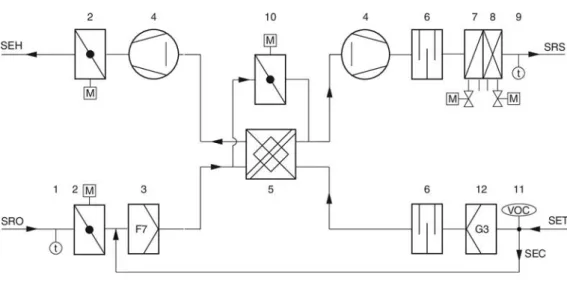
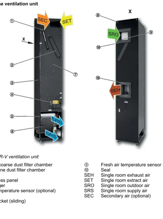
If necessary, the air is heated or cooled by the heat exchanger before it is discharged to the room as a displacement flow (for 4-pipe systems this is optional). The exhaust air first passes a G3 filter, then flows through the recuperative heat exchanger, the exhaust air fan and the motorized shut-off damper before being discharged outside as exhaust air.
Symbols used in this manual
Correct use
Use, installation, operation, maintenance or repair not described in this manual - Work should be carried out by unqualified individuals. Use of non-original spare parts or accessories whose quality and performance are not equivalent to the original parts.
Safety signs
Electric shock hazard
Risks from rotating parts
Health risks due to hygiene issues
Risks caused by an unsuitable installation
Qualified staff
Personal protective equipment
Safety shoes protect the feet from crushing, falling parts and prevent slipping on a slippery floor. Note the damage on the shipping documents or on the shipping company's delivery note. If possible, take the module in its transport packaging to the installation site.
General installation information
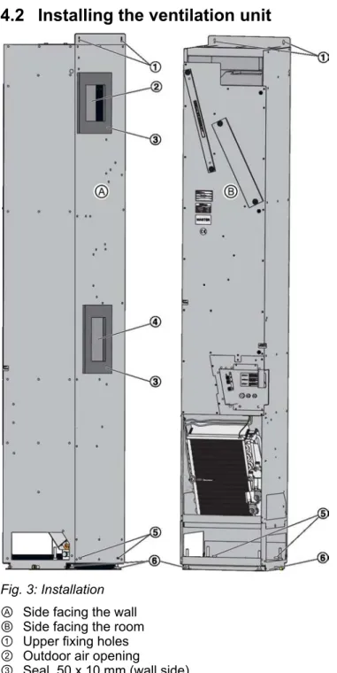
Installing the ventilation unit
Ensure that the unit can be connected to the pipework and to the mains supply. The openings for the air (Fig. 3/2 and Fig. 3/4) must be in line with the prepared openings in the outer wall; adjust the feet if necessary. Protect the ventilation unit with the optional outer casing or by another outer casing supplied by others.
The outer casing must prevent unauthorized individuals from entering the unit and being injured (eg by electric shock). Make sure that the air can circulate around the unit even with the outer casing. If there is a long gap between installation and commissioning of the unit, we recommend the following measures to avoid cumbersome cleaning procedures at the time of commissioning.
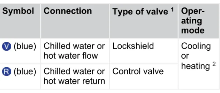
Connecting the water pipes
Making electrical connections
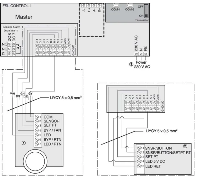
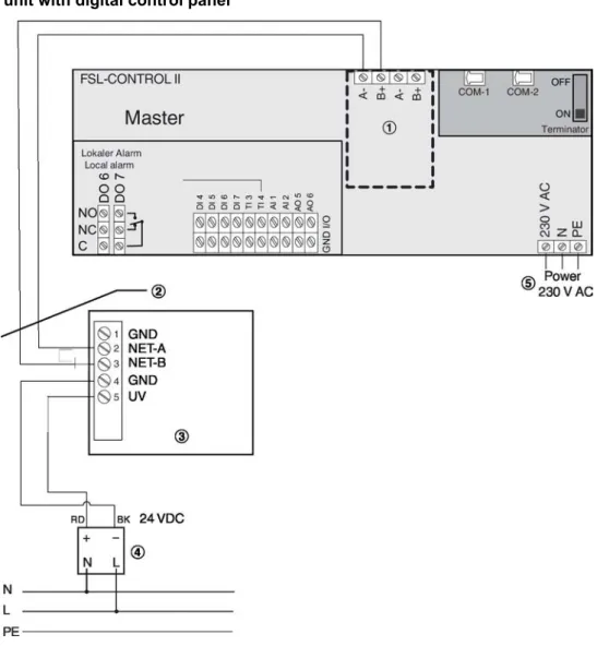
Wiring
The digital control panel is a dedicated device that can be used together with the ventilation unit (master). Both carry the same serial number, which is found on the rating plate (ventilation unit) or on the packaging (control panel). Note: The overall dimensions depend on the frame chosen for the switch.
Attach the LON interface card to the screws (other) in the distribution box; max. Place the mounting ring of the LON interface card flat against the side of the wall; do not cover with paint or wallpaper. ② Analog control panel with or without selector switch (digital control panel can only be used for independent operation of the ventilation unit).
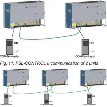
FSL-CONTROL II communication
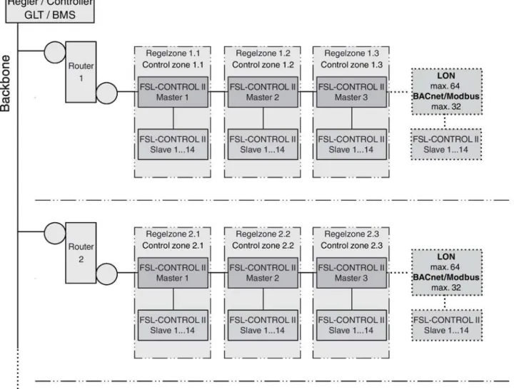
You can interconnect control zones using a standard network such as LON FTT10, BACnet MS/TP or Modbus RTU. This requires a bus interface card to be connected to the FSL-CONTROL II master controller. If the master controller is integrated with a central BMS (by others), it acts as a slave within the bus network, but as a master within the FSL-CONTROL II system.
Depending on the network topology, controllers at the end of a chain may be connected to one bus, controllers in other positions in the chain may be connected to two buses. Strip the insulation from the bus cable (at least two wires), insert the bare wires into the terminals and tighten the screws by hand. Commissioning: Press the service pin push button and download the application software for the LonWorks node.
Binding: Creates the logical bindings for the network variables to be transferred by the LonWorks interface card (expansion module). Before using a BACnet MS/TP or Modbus RTU interface card, you must configure it on the actual application. Check and make sure that the actual supply voltage is the same as the one given on the rating plate.
For units with the integral FSL‑CONTROL II control system Ä Installation and Configuration Manual, FSL‑CONTROL II Single Room Control.
Analogue control panel
Digital control panel
Before you start working on the device, you must switch off the power supply and secure it against unintentional switching on again. The degree of contamination of a ventilation unit largely depends on the location of the building and the duration of daily use of the unit. During the first three months after initial commissioning, increased exposure to dust due to construction work is to be expected; therefore, the filters should be replaced after three months and the device cleaned.
We also recommend that you randomly check the contamination level of the filters every three months during the first year and use the result as a basis for setting further maintenance intervals. Hygiene inspections should be carried out by suitably qualified persons and on a random selection of typical ventilation units. Do not use organic solvents (such as acetone or methanol) to clean the heat exchanger.
Maintenance
Checking and replacing the filter
If the filter is intact, free of contamination or deposits and has been used for less than 1 year, place it back in the filter chamber. If the filter has been in use for a year or no longer meets the technical or hygienic requirements, replace it. If the filter operating hours counter is used in FSL-CONTROL II, reset it after a filter change Ä Installation and configuration manual FSL-CONTROL II.
Cleaning the heat exchanger and con-
Switch off the supply voltage and secure it against being switched on again before working on the unit.
Cleaning the recuperative heat
Be careful not to damage the fiberglass cloth or insulation when cleaning or servicing the unit after the cover plate has been opened or removed. Do not use organic solvents (such as ace- Maintenance> Cleaning the recovery heat. Place the recovery heat exchanger in an upright position and let it dry overnight.
Place the recuperative heat exchanger on the rails and push it back into the opening. Be sure to insert the protective earth conductor (Fig. 26/5) when attaching the cover plate. Place the protective earth conductor (Fig. 26/5) on the cover plate, then place the panel back on the ventilation unit (Fig. 26/3).

Replacement parts list
Repair
Repair
Hold the new actuator in the same position as the one you removed, then push it onto the drive shaft. Disconnect the plug connections (Fig. 32/4) for the actuators; to do this, pull the plugs from above. Be sure to insert the protective earth conductor when fixing the inspection access panel.
Technical data
Performance data
We hereby declare that the machine is in compliance with all relevant provisions of the following EU Directives: Electromagnetic compatibility) Directive 2004/108/EC of the European Parliament and of the Council of 15 December 2004 on the approximation of the laws of the Member States relating to electromagnetic compatibility and repealing Directive 89/336/EEC. Voltage limits) Directive of the European Parliament and of the Council of 12 December 2006 on the harmonization of the laws of the Member States relating to electrical equipment designed for use within certain voltage limits (codified version).
TROX GmbH, Heinrich-Trox-Platz, D-47504 Neukirchen-Vluyn, Germany, hereby confirms that the decentralized ventilation units of types SCHOOLAIR-B/-D/-V meet the hygiene requirements specified by the standards and regulations listed below. For the purpose of this declaration of conformity, a sample of each type mentioned above at the TROX GmbH factory, Heinrich-Trox-Platz, 47504 Neukirchen-Vluyn, Germany, was viewed and related data sheets, technical literature and inspection reports were assessed. The examination of the above sample equipment and the evaluation of the available documents showed that the hygiene requirements specified by the above standards and regulations are met.
We hereby confirm that the decentralized ventilation units of the SCHOOLAIR-B/-D/-V types meet the hygiene requirements of the specified standards and regulations.