Time averaged adiabatic Potentials (TAAP)
(1 µK iso-potential surfaces in a TAAP trap)
PRL 99:8 083001 (2007)
Time averaged adiabatic Potentials (TAAP)
(1 µK iso-potential surfaces in a TAAP trap)
PRL 99:8 083001 (2007)
Cretan Matter-Waves Group
FORTH IESL
Guided MatterWave Interferometers
Wolf von Klitzing
Benasque
06.05.2015
Outline
• Interferometry — Why? How?
• Time-Averaged Adiabatic Potentials (TAAP)
• Bucket Atomtronics
• Atom Lasers
Matter-Wave Interferometry Why???
Plus
+ Internal States
+ Gravitation
+ Atom-Atom Interaction
! Heisenberg Limited Detection
Sensitivity (Sagnac)
5x10 10
⇤ = 4⇥
v ⇥A
⇥ atom
⇥ light = light c 0
h/m =
8.2 m 2
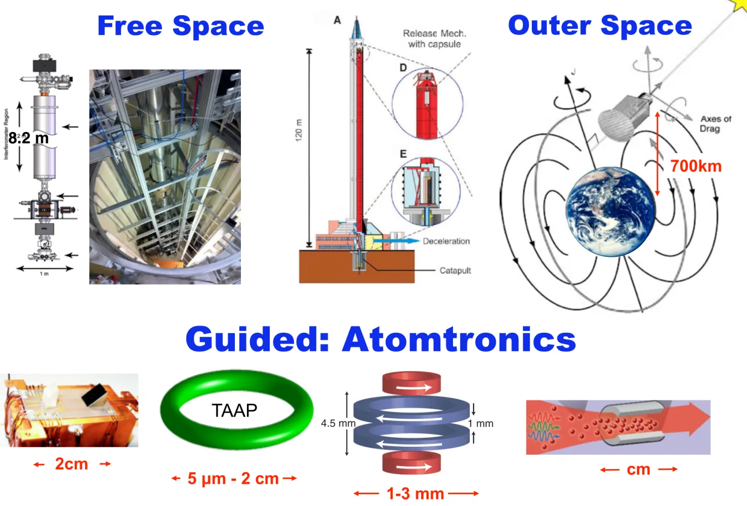
Free Space
ESA STE-QUEST
700km
Stanford
Outer Space
Matter-Wave Interferometers
120 m
ZARM drop Tower
Repetition rate:
~23 μHz
Preparation time:
~10 years
Shown here is the Goddard-designed breadboard laser system critical to advancing atom-optics instruments. The device will be tested in the Stanford
University drop tower. Credit: NASA/Pat Izzo
http://www.sciencedaily.com/releases/2012/10/121018185947.htm
8.2 m 2
Free Space
Stanford
Matter-Wave Interferometers
120 m
ZARM drop Tower
Repetition rate:
~23 μHz
Preparation time:
~10 years 700km
Outer Space
Matter-Wave Interferometers
5 µm - 2 cm
TAAP
Bose-Einstein Condensation in a Circular Waveguide
S. Gupta, K. W. Murch, K. L. Moore, T. P. Purdy, and D. M. Stamper-Kurn
Department of Physics, University of California, Berkeley, California 94720, USA (Received 27 April 2005; published 29 September 2005)
We have produced Bose-Einstein condensates in a ring-shaped magnetic waveguide. The few- millimeter diameter, nonzero-bias ring is formed from a time-averaged quadrupole ring. Condensates that propagate around the ring make several revolutions within the time it takes for them to expand to fill the ring. The ring shape is ideally suited for studies of vorticity in a multiply connected geometry and is promising as a rotation sensor.
DOI: 10.1103/PhysRevLett.95.143201 PACS numbers: 39.20.+q, 03.75.2b, 05.30.Jp, 39.25.+k
The long range phase coherence of superfluids and superconductors, aside from leading to interesting physical effects, is also of practical importance in allowing for precise measurement devices based on quantum interfer- ence. In such devices, spatially separated paths forming a multiply connected geometry are imposed on the macro- scopic quantum system. For example, a SQUID magne- tometer makes use of a superconducting ring interrupted by Josephson junctions to allow continuous sensitivity to magnetic fields. A similar geometry was used in a super- fluid
3He gyroscope [1].
Dilute gas superfluids have now enabled novel forms of matter-wave interferometry. Precise sensors of rotation, acceleration, and other sources of quantal phases [2,3]
using trapped or guided atoms have been envisioned. In particular, the sensitivity of atom-interferometric gyro- scopes is proportional to the area enclosed by the closed loop around which atoms are guided [4]. Such consider- ations motivate the development of closed-loop atom waveguides that enclose a sizable area.
A number of multiply connected trapping geometries for cold atoms have been discussed. Optical traps using high- order Gauss-Laguerre beams were proposed [5,6], and hollow light beams were used to trap nondegenerate atoms in an array of small-radius rings [7]. Large-scale magnetic storage rings were developed for cold neutrons [8] and discussed for atomic hydrogen [9]. More recently, closed-loop magnetic waveguides were demonstrated for laser cooled atoms [10,11]. Unfortunately, these guides are characterized by large variations in the potential energy along the waveguide and by high transmission losses at points where the magnetic field vanishes.
In this Letter, we report the creation of a smooth, stable circular waveguide for ultracold atoms. A simple arrange- ment of coaxial electromagnetic coils was used to produce a static ring-shaped magnetic trap, which we call the quadrupole ring (Q ring), in which strong transverse con- finement is provided by a two-dimensional quadrupole field. Atoms trapped in the Q ring experience large Majorana losses, but we can eliminate such losses with a time-orbiting ring trap (TORT) [12]. In this manner, stable circular waveguides with diameters ranging from 1.2 to
3 mm were produced. Finally, we report on the production of Bose-Einstein condensates (BECs) in a portion of the circular waveguide, and on the guiding of an ultracold atomic beam for several revolutions around the guide.
This ring-shaped trap presents opportunities for studies of BECs that are homogeneous in one dimension and therefore of the unterminated propagation of sound waves [13] and solitons [14–16], of persistent currents [17–20], of quantum gases in low dimensions, and of matter-wave interferometry.
To explain the origin of the quadrupole ring trap, we consider a cylindrically symmetric static magnetic field B ~
cin a source-free region. Expanding B ~
cto low order about a point (taken as the origin) on the axis where the field magnitude has a local quadratic minimum, we have
B ~
c! B
0z ^ " B
00z2
!"
z
2# x
2" y
22
#
z ^ # z $ x x ^ " y y ^ %
$
; (1) where B
0> 0 is the field magnitude at the origin, B
00zis the
x z y
(a)
x z
(b)
z
x (c)
(d) z
x 1 mm
4.5 mm
FIG. 1 (color). Forming a circular magnetic waveguide.
(a) Four coaxial circular electromagnets (see [21] for details) are used to generate both the static (currents as shown) and rotating fields needed for the waveguide. Axes are indicated;
gravity points along # z. (b) As shown schematically, the field ^ (arrows) from just the two outer coils (curvature coils, outer pair) points axially in the midplane between the coils, with largest fields at the axis. (c) Adding a uniform opposing bias field (using antibias coils, inner pair) produces a ring of field zeros ( & ) in the x- ^ y ^ plane around which weak-field seeking atoms (shaded re- gion) are trapped. (d) Rapidly rotating the field zeros around the trapped atoms produces the TORT.
PRL 95, 143201 (2005) P H Y S I C A L R E V I E W L E T T E R S
week ending30 SEPTEMBER 2005
0031-9007= 05=95(14)=143201(4)$23.00 143201-1 © 2005 The American Physical Society
1-3 mm 2cm
Guided: Atomtronics
cm 8.2 m 2
700km
Outer Space
Free Space
Why Guiding is BAD
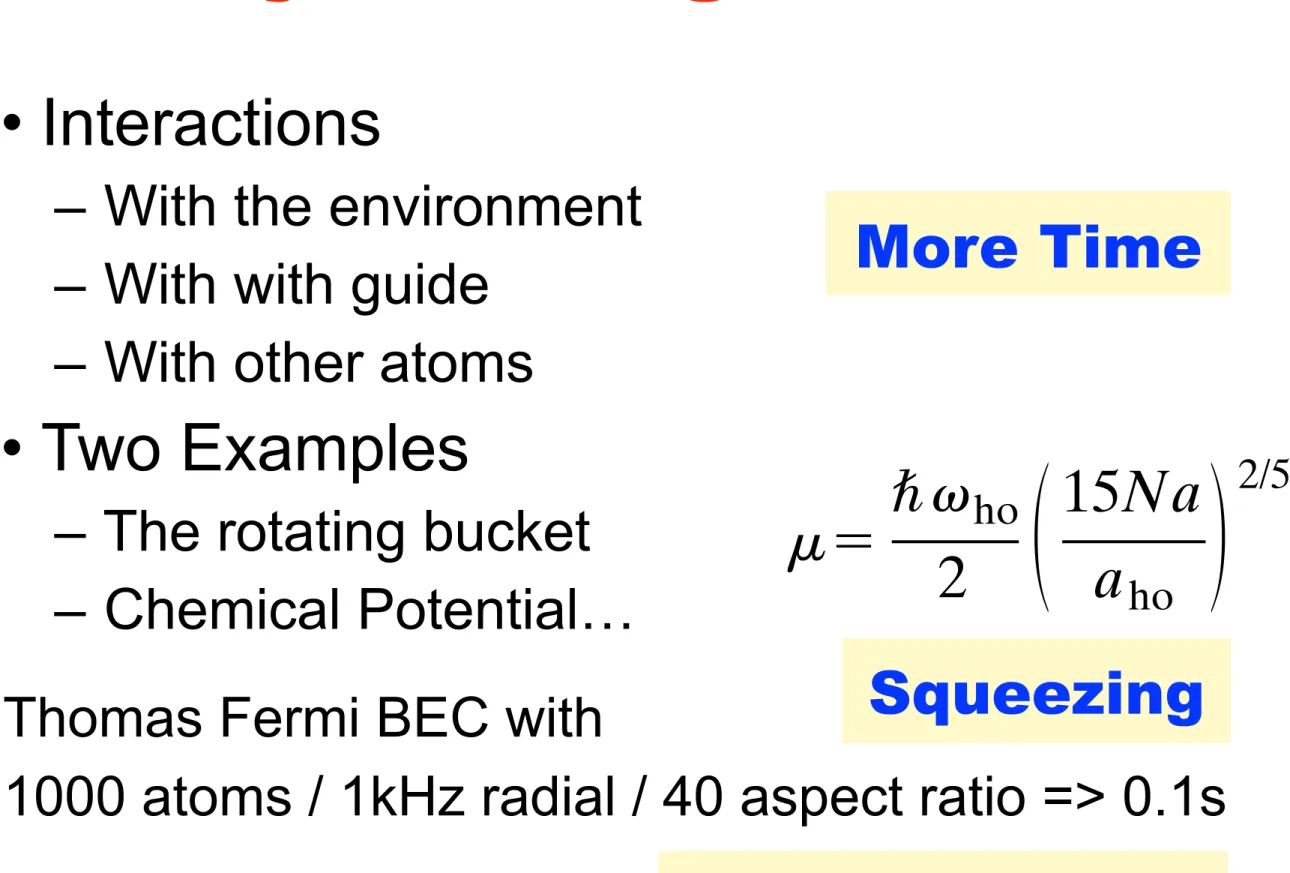
• Interactions
– With the environment – With with guide
– With other atoms
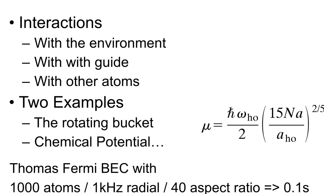
• Two Examples
– The rotating bucket – Chemical Potential…
Stoof, and Hulet (1998), Ueda and Huang (1998), and Ueda and Leggett (1998).
D. Large-N limit for repulsive forces
In the case of atoms with repulsive interaction ( a . 0), the limit Na / a ho @ 1 is particularly interesting, since this condition is well satisfied by the parameters N, a, and a ho used in most of current experiments. More- over, in this limit the predictions of mean-field theory take a rather simple analytic form (Edwards and Bur- nett, 1995; Baym and Pethick, 1996).
As regards the ground state, the effect of increasing the parameter Na / a ho is clearly seen in Fig. 9: the atoms are pushed outwards, the central density becomes rather flat, and the radius grows. As a consequence, the quantum-pressure term in the Gross-Pitaevskii Eq. (39), proportional to π 2 A n ( r), takes a significant contribution only near the boundary and becomes less and less im- portant with respect to the interaction energy. If one neglects completely the quantum pressure in Eq. (39), one gets the density profile in the form
n ~ r ! 5 f 2 ~ r ! 5 g 2 1 @ m 2 V ext ~ r !# (50) in the region where m . V ext ( r), and n 5 0 outside. This is often referred to as Thomas-Fermi (TF) approxima- tion.
The normalization condition on n ( r) provides the re- lation between chemical potential and number of par- ticles:
m 5 \ v ho
2 S 15Na a ho D 2/5 . (51)
Note that the chemical potential depends on the trap- ping frequencies, entering the potential V ext given in Eq.
(1), only through the geometric average v ho [see Eq.
(4)]. Moreover, since m 5 ] E / ] N , the energy per particle turns out to be E / N 5 (5/7) m . This energy is the sum of the interaction and oscillator energies, since the kinetic energy gives a vanishing contribution for large N. Fi- nally, in the same limit, the release energy (45) coincides with the interaction energy: E rel / N 5 (2/7) m .
The chemical potential, as well as the interaction and oscillator energies obtained by numerically solving the GP Eq. (39) become closer and closer to the Thomas- Fermi values when N increases (see, for instance, Dal- fovo and Stringari, 1996). For sodium atoms in the MIT traps, where N is larger than 10 6 , the Thomas-Fermi ap- proximation is practically indistinguishable from the so- lution of the GP equation. The release energy per par- ticle measured by Mewes et al. (1996a) is indeed well fit with a N 2/5 law, as shown in Fig. 11. The same agreement is expected to occur for rubidium atoms in the most re- cent JILA traps, having N larger than 10 5 (Matthews et al., 1998).
The density profile (50) has the form of an inverted parabola, which vanishes at the classical turning point R defined by the condition m 5 V ext ( R). For a spherical
trap, this implies m 5 m v ho 2 R 2 /2 and, using result (51) for
m , one finds the following expression for the radius of the condensate
R 5 a ho S 15Na a ho D 1/5 (52)
which grows with N. For an axially symmetric trap, the widths in the radial and axial directions are fixed by the conditions m 5 m v ' 2 R ' 2 /2 5 m v z 2 Z 2 /2. It is worth men- tioning that, in the case of the cigar-shaped trap used at MIT, with a condensate of about 10 7 sodium atoms, the axial width becomes macroscopically large ( Z ; 0.3 mm), allowing for direct in situ measurements.
The value of the density (50) in the center of the trap is n TF (0) 5 m / g . It is worth stressing that this density is much lower than the one predicted for noninteracting particles. In the latter case, using Eq. (3) one gets n ho (0) 5 N /( p 3/2 a ho 3 ). The ratio between the central densities in the two cases is then
n TF ~ 0 !
n ho ~ 0 ! 5 15 2/5 p 1/2
8 S Na a ho D 2 3/5 , (53)
and decreases with N. For the available traps with 23 Na and 87 Rb, where Na / a ho ranges from about 10 to 10 4 , the atom-atom repulsion reduces the density by one or two orders of magnitude, which is a quite remarkable effect for such a dilute system. An example was already shown in Fig. 3; in that case, the number of particles is about 80 000 and Na / a ho ; 300.
In Fig. 13(a) we show the density profile for a gas in a spherical trap with Na / a ho 5 100. The comparison with the exact solution of the GP Eq. (39) shows that the TF
FIG. 13. Density profile for atoms interacting with repulsive forces in a spherical trap, with Na / a ho 5 100. Solid line: solu- tion of the stationary GP Eq. (39). Dashed line: Thomas-Fermi approximation (50). In the upper part, the atom density is plot- ted in arbitrary units, while the distance from the center of the trap is in units of a ho . The classical turning point is at R . 4.31a ho . In the lower part, the column density for the same system is reported.
478 Dalfovo et al. : Bose-Einstein condensation in trapped gases
Rev. Mod. Phys., Vol. 71, No. 3, April 1999
Thomas Fermi BEC with
1000 atoms / 1kHz radial / 40 aspect ratio => 0.1s
Why Guiding is GOOD
• Interactions
– With the environment – With with guide
– With other atoms
• Two Examples
– The rotating bucket – Chemical Potential…
Stoof, and Hulet (1998), Ueda and Huang (1998), and Ueda and Leggett (1998).
D. Large-N limit for repulsive forces
In the case of atoms with repulsive interaction ( a . 0), the limit Na / a ho @ 1 is particularly interesting, since this condition is well satisfied by the parameters N, a, and a ho used in most of current experiments. More- over, in this limit the predictions of mean-field theory take a rather simple analytic form (Edwards and Bur- nett, 1995; Baym and Pethick, 1996).
As regards the ground state, the effect of increasing the parameter Na / a ho is clearly seen in Fig. 9: the atoms are pushed outwards, the central density becomes rather flat, and the radius grows. As a consequence, the quantum-pressure term in the Gross-Pitaevskii Eq. (39), proportional to π 2 A n ( r), takes a significant contribution only near the boundary and becomes less and less im- portant with respect to the interaction energy. If one neglects completely the quantum pressure in Eq. (39), one gets the density profile in the form
n ~ r ! 5 f 2 ~ r ! 5 g 2 1 @ m 2 V ext ~ r !# (50) in the region where m . V ext ( r), and n 5 0 outside. This is often referred to as Thomas-Fermi (TF) approxima- tion.
The normalization condition on n ( r) provides the re- lation between chemical potential and number of par- ticles:
m 5 \ v ho
2 S 15Na a ho D 2/5 . (51)
Note that the chemical potential depends on the trap- ping frequencies, entering the potential V ext given in Eq.
(1), only through the geometric average v ho [see Eq.
(4)]. Moreover, since m 5 ] E / ] N , the energy per particle turns out to be E / N 5 (5/7) m . This energy is the sum of the interaction and oscillator energies, since the kinetic energy gives a vanishing contribution for large N. Fi- nally, in the same limit, the release energy (45) coincides with the interaction energy: E rel / N 5 (2/7) m .
The chemical potential, as well as the interaction and oscillator energies obtained by numerically solving the GP Eq. (39) become closer and closer to the Thomas- Fermi values when N increases (see, for instance, Dal- fovo and Stringari, 1996). For sodium atoms in the MIT traps, where N is larger than 10 6 , the Thomas-Fermi ap- proximation is practically indistinguishable from the so- lution of the GP equation. The release energy per par- ticle measured by Mewes et al. (1996a) is indeed well fit with a N 2/5 law, as shown in Fig. 11. The same agreement is expected to occur for rubidium atoms in the most re- cent JILA traps, having N larger than 10 5 (Matthews et al., 1998).
The density profile (50) has the form of an inverted parabola, which vanishes at the classical turning point R defined by the condition m 5 V ext ( R). For a spherical
trap, this implies m 5 m v ho 2 R 2 /2 and, using result (51) for
m , one finds the following expression for the radius of the condensate
R 5 a ho S 15Na a ho D 1/5 (52)
which grows with N. For an axially symmetric trap, the widths in the radial and axial directions are fixed by the conditions m 5 m v ' 2 R ' 2 /2 5 m v z 2 Z 2 /2. It is worth men- tioning that, in the case of the cigar-shaped trap used at MIT, with a condensate of about 10 7 sodium atoms, the axial width becomes macroscopically large ( Z ; 0.3 mm), allowing for direct in situ measurements.
The value of the density (50) in the center of the trap is n TF (0) 5 m / g . It is worth stressing that this density is much lower than the one predicted for noninteracting particles. In the latter case, using Eq. (3) one gets n ho (0) 5 N /( p 3/2 a ho 3 ). The ratio between the central densities in the two cases is then
n TF ~ 0 !
n ho ~ 0 ! 5 15 2/5 p 1/2
8 S Na a ho D 2 3/5 , (53)
and decreases with N. For the available traps with 23 Na and 87 Rb, where Na / a ho ranges from about 10 to 10 4 , the atom-atom repulsion reduces the density by one or two orders of magnitude, which is a quite remarkable effect for such a dilute system. An example was already shown in Fig. 3; in that case, the number of particles is about 80 000 and Na / a ho ; 300.
In Fig. 13(a) we show the density profile for a gas in a spherical trap with Na / a ho 5 100. The comparison with the exact solution of the GP Eq. (39) shows that the TF
FIG. 13. Density profile for atoms interacting with repulsive forces in a spherical trap, with Na / a ho 5 100. Solid line: solu- tion of the stationary GP Eq. (39). Dashed line: Thomas-Fermi approximation (50). In the upper part, the atom density is plot- ted in arbitrary units, while the distance from the center of the trap is in units of a ho . The classical turning point is at R . 4.31a ho . In the lower part, the column density for the same system is reported.
478 Dalfovo et al. : Bose-Einstein condensation in trapped gases
Rev. Mod. Phys., Vol. 71, No. 3, April 1999
Thomas Fermi BEC with
1000 atoms / 1kHz radial / 40 aspect ratio => 0.1s
Squeezing More Time
Miniaturisation!
Atomtronics Circuits
• Bend - Closed Loop
• Smooth / Coherent
• Dynamically Controllable
Matter-Wave Guides
Boshier, Benasque 2015
Atomtronics Circuits
• Bend - Closed Loop
• Smooth / Coherent
• Dynamically Controllable
Matter-Wave Guides
Boshier Criteria of Atomtronics
• L oop
• S mooth
• D ynamic
Boshier, Benasque 2015
Atomtronics Circuits
• Bend - Closed Loop
• Smooth / Coherent
• Dynamically Controllable
Matter-Wave Guides
• Dipole Traps & Guides
• Magnetic Fields
Boshier Criteria of Atomtronics
• L oop
• S mooth
• D ynamic
Boshier, Benasque 2015
Dipole Guides
9.6 Theory of the dipole force 199
The force that depends on the in-phase component of the dipole u is the dipole force and the other part is the scattering force. Using the expressions for u and v given in eqn 7.68 and the Rabi frequency Ω = eX 12 E 0 / ! , we find that
F scatt = ! k Γ 2
Ω 2 /2
δ 2 + Ω 2 /2 + Γ 2 /4 , (9.42) which is consistent with eqn 9.4, and
F dipole = − ! δ 2
Ω
δ 2 + Ω 2 /2 + Γ 2 /4
∂ Ω
∂ z , (9.43)
where δ = ω − ω 0 is the frequency detuning from resonance. The ex- pression for the scattering force has been repeated here for ease of com- parison with eqn 9.43. These forces have essentially the same frequency dependence as in the classical model, with a line width that is power broadened so that β ←→ Γ(1 + 2Ω 2 /Γ 2 ) 1/2 . The dipole force is zero on resonance (F dipole = 0 for δ = 0), and for | δ | ≫ Γ (and an intensity such that | δ | ≫ Ω) the dipole force equals the derivative of the light shift (eqn 7.93):
F dipole ≃ − ∂
∂ z
! ! Ω 2 4δ
"
. (9.44)
Thus the light shift, or a.c. Stark shift, for an atom in the ground state acts as a potential U dipole in which the atom moves. More generally, in three dimensions
F dipole = −
#
$ e x ∂
∂ x + $ e y ∂
∂ y + $ e z ∂
∂ z
%
U dipole = −∇ U dipole , (9.45) where
U dipole ≃ ! Ω 2
4δ ≡ ! Γ 8
Γ δ
I
I sat . (9.46)
When δ is positive (ω > ω 0 ) this potential has a maximum where the intensity is highest—the atom is repelled from regions of high intensity.
In the opposite case of frequency detuning to the red ( δ negative) the dipole force acts in the direction of increasing I , and U dipole is an at- tractive potential—atoms in a tightly-focused laser beam are attracted towards the region of high intensity, both in the radial direction and along the axis of the beam. This dipole force confines atoms at the fo- cus of a laser beam in an analogous way to optical tweezers to create
a dipole-force trap. 42 Normally, dipole traps operate at large frequency 42 The situation for an atom with de- tuning δ < 0 resembles that of a di- electric sphere with a refractive index greater than the surrounding medium.
detuning ( | δ | ≫ Γ), where to a good approximation eqn 9.3 becomes R scatt ≃ Γ
8
Γ 2 δ 2
I
I sat . (9.47)
This scattering rate depends on I/δ 2 , whereas the trap depth is pro- portional to I/δ (in eqn 9.46). Thus working at a sufficiently large fre- quency detuning reduces the scattering whilst maintaining a reasonable trap depth (for a high intensity at the focus of the laser beam). Usually
- Free space beams - Lattices
- Paintings
- Fibres
Dipole Guides: Beam Splitters
- Free space beams - Lattices
- Paintings
- Fibres
Dipole: Rings
Experimental demonstration of painting arbitrary and dynamic potentials for Bose-Einstein condensates K. Henderson et al. N.J.Phys 11: 043030 (2009)
- Free space beams - Lattices
- Paintings
- Fibres
G. D. MCDONALD et al. PHYSICAL REVIEW A 88, 053620 (2013)
Cross DM
Imaging DM
Lattice
Lattice Waveguide
Science Cell
y
x z
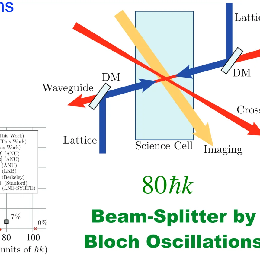
FIG. 2. (Color online) We form a BEC in a cross-beam dipole trap, before releasing it into the waveguide. After it has expanded for 125 ms, we flash on the cross beam again to apply δ-kick cooling to the atoms. Our interferometer is formed by Bragg and Bloch pulses from counterpropagating beams aligned collinearly with the waveguide beam with the use of dichroic mirrors (DM).
however this implementation uses the optically generated harmonic potential of our dipole cross beam. This technique effectively rotates the ellipse describing position-momentum correlation along the waveguide so as to have minimal spread in momenta across the cloud [see Fig. 3(c)]. In the case of a nonpoint source of atoms, and due to both the finite size and anharmonicity of our dipole cross-beam potential, our δ -kick cooling is not ideal, so in practice we calibrate the process by measuring the fringe visibility of a 40¯ hk interferometer performed after various configurations. We find t f = 125 ms for our optimal δ -kick cooling configuration. Figure 3(e) shows this calibration and demonstrates that a narrow-momentum- width atom source is critical for reasonable fringe visibility in an LMT interferometer. By a fit to the expanding δ -kick-cooled cloud width [Fig. 3(f), yellow triangles] we see that our inter- ferometric atom source now has a momentum width of 0.05¯ hk.
Our optical-lattice laser setup has been described previously [5]. We have up to 50 mW in each of two counterpropagating beams. These are aligned collinearly with the waveguide in a two-step process. First, the small fraction of waveguide light which reflects off the dichroic mirror (see Fig. 2) is back- coupled into the optical fiber which one of the lattice beams comes from. Second, the other lattice beam is coupled into the same optical fiber. The lattice beams are collimated with a full e 1
2width of 1.85 mm and detuned 105 GHz to the blue from the | F = 1 ⟩ → | F ′ = 2 ⟩ transition of the D 2 line in 87 Rb, which keeps the number of spontaneous emissions below 1%
of our total atom number during our interferometric sequence.
Arbitrary, independent control of the frequency detuning and amplitude of each beam is achieved using a direct digital synthesizer. Prior to our interferometer, a velocity-selection Bragg pulse of 10¯ hk is used to isolate the portion of atoms ( ≈ 80%) with a narrow momentum width σ p from those not properly cooled by our δ -kick process. For clarity, our constant-acceleration Bloch (CAB) interferometer sequences will be described in the frame of these velocity-selected atoms, which are themselves moving at 10¯ hk with respect to the laboratory frame. Each part of the sequence is labeled with roman numerals corresponding to its depiction in Fig. 4.
(i) Our CAB (CAB2) sequence begins with a 2n¯ hk π 2 Bragg pulse with n = 5 applied to the atoms to coherently split them
0 100 200 300
0 100 200 300 400 σ z
0.1 0.2 0.3 0.4
50 100 150
W av eguide In tensit y during delta-kic k (W)
5.1 4.9 4.7 4.5 4.3 4.1 3.9 3.7
x x x
(a) (b) (c)
(d) (e)
(f)
delta-kicked
p x p x p x
Time before δ -kick (ms)
FIG. 3. (Color online) (a) Immediately after the condensate is released into the waveguide, it has a minimal spread in spatial extent and in momentum width. (b) Over time, the cloud expands ballistically until momentum is well correlated with position along the guide. (c) Application of a harmonic potential for a short time (the δ kick) reduces the momentum spread of the cloud, which now has a larger spatial extent. (d) It is important to adjust the waveguide intensity so that the δ-kick cross-beam pulse is applied symmetrically over the cold cloud, otherwise transverse oscillations will occur in the guide. Here we show this adjustment process, in which the cloud is photographed a certain time after δ-kick cooling. The cloud is observed to oscillate if the waveguide power is either side of 4.5 W.
At 3.7 W we can see atoms falling out of the guide as they oscillate.
(e) We optimize our δ-kick cooling by looking at the fringe visibility (as measured by a sinusoidal fit) of a 40¯ hk interferometer. We find our best visibility when our cross beam flashes on 125 ms after the atoms are released into the waveguide. (f) Of course, this collimation is imperfect; here we show the longitudinal width σ
xof the cloud expanding after release as measured by the standard deviation of a Gaussian fit, both with (yellow triangles) and without (blue diamonds) the cross-beam flash at 125 ms. Also shown is the transverse width σ
z(red squares). All widths are measured after an extra 22 ms of ballistic expansion after the waveguide expansion time shown in (f).
into two momentum states, one in the initial 0¯ hk state, the other traveling at 10¯ hk. (ii) This is followed by an extra 10¯ hk Bragg kick which is given to the faster 10¯ hk atoms, taking them to 20¯ hk. (iii) The 0¯ hk atoms are then loaded into a Bloch lattice of 10–20 recoil energies over a rise time of T r = 110 µs which is accelerated in the other direction up to 2n b hk ¯ = − 60¯ hk ,
053620-2
Dipole Guides: Beam Splitters
PHYSICAL REVIEW A 88, 053620 (2013)
80¯ hk momentum separation with Bloch oscillations in an optically guided atom interferometer
G. D. McDonald,
*C. C. N. Kuhn, S. Bennetts, J. E. Debs, K. S. Hardman, M. Johnsson, J. D. Close, and N. P. Robins
Quantum Sensors Laboratory, Department of Quantum Science, Australian National University, Canberra, Australian Capital Territory 0200, Australia
(Received 30 June 2013; published 18 November 2013)
We demonstrate phase sensitivity in a horizontally guided, acceleration-sensitive atom interferometer with a momentum separation of 80¯ hk between its arms. A fringe visibility of 7% is observed. Our coherent pulse sequence accelerates the cold cloud in an optical waveguide, an inherently scalable route to large momentum separation and high sensitivity. We maintain coherence at high momentum separation due to both the transverse confinement provided by the guide and our use of optical δ-kick cooling on our cold-atom cloud. We also construct a horizontal interferometric gradiometer to measure the longitudinal curvature of our optical waveguide.
DOI: 10.1103/PhysRevA.88.053620 PACS number(s): 37.25. + k, 03.75.Gg, 37.10.Jk, 67.85.Hj
Cold-atom interferometers measure parameters of interest (for example an acceleration) by comparing the phase accu- mulated by an atom as it traverses either of two trajectories, known as the arms of the interferometer. Applications for such high-precision measurement devices include inertial sensing [1], gravitational-wave detection [2], measurements of the fine-structure constant [3], and tests of general relativity [4].
The sensitivity of an atom-interferometric accelerometer is proportional to its enclosed space-time area. Therefore, a key technology to enable the next generation of these devices is large momentum transfer (LMT), in which the enclosed space- time area is enlarged by increasing the momentum difference
" p of the two interferometer arms. Various configurations
for an LMT interferometer have been demonstrated [5–13]
(see Fig. 1) with " p up to 102¯ hk [10], k being the wave vector of the light used to effect the transition. However, a direct measurement of the interferometric phase and hence the ability to make an acceleration measurement has proved elusive beyond " p = 24¯ hk [6].
Here we measure the interferometric phase in a Bloch- oscillation-based optically guided LMT atom interferometer with a momentum separation of " p up to 80¯ hk. We use this phase measurement to calculate the tilt of the waveguide with respect to gravity. We maintain a fringe visibility of 7%
at 80¯ hk separation, as measured by a sinusoidal fit to the data [14], which we attribute to both our narrow longitudinal velocity width after optical δ -kick cooling and the transverse confinement of the optical guide. We characterize the longi- tudinal curvature of our optical waveguide by constructing a gradiometer in the guide. We also demonstrate a single beam splitter with " p = 510¯ hk , and an exponential decay time for the atoms held in the optical waveguide of 3.3 s, demonstrating the scalability of this approach to LMT.
Our interferometric source is a
87Rb condensate formed by radio-frequency evaporation of atoms in their
| F = 1,m
F= − 1 ⟩ lower ground state in a hybrid magnetic and optical configuration [15] before transferring them into a crossed-beam optical-dipole trap (shown in Fig. 2). The cross beam is sourced from a 2-nm-linewidth metal cutting laser operating at 1090 nm, while the waveguide beam is
*
[email protected]; http://atomlaser.anu.edu.au/
0 20 40 60 80 100
0 20 40 60 80 100
Fr in ge V is ib ili ty (% )
CAB (This Work)CAB2 (This Work) MZ (This Work)
Ref. [5] (ANU) Ref. [12] (ANU) Ref. [13] (ANU)
Ref. [6] (Berkeley) Ref. [8] (LNE-SYRTE) Ref. [10] (Stanford) Ref. [7] (LKB)
7% 0%
Momentum Separation ∆p (units of k)
FIG. 1. (Color online) Fringe visibility for various LMT ac- celerometer experiments [5–13] as measured by the peak-to-peak amplitude of a sinusoidal fit to each fringe set. A standard 10¯ hk Mach-Zehnder (MZ) and both the constant-acceleration Bloch (CAB) and CAB2 pulse sequences used in this work (see text) are displayed for comparison. It should be noted that the fringe visibility of the interferometer with " p = 102¯ hk in Ref. [10] is zero, as phase noise prevented any phase measurement from being performed.
a single-frequency laser with 1 MHz linewidth operating at 1064 nm. The crossed dipole beams are adiabatically ramped down from 12 W each to 4.3 W and 175 mW, respectively, over 3 s which further evaporatively cools the atoms, producing a Bose-Einstein condensate (BEC) of 2 × 10
6atoms with a repetition rate of 2.5/min. We measure the axial trap frequency just before release into the waveguide to be 9 Hz, by measuring the momentum oscillations after a 2¯ hk Bloch acceleration. Similarly, by misaligning the Bragg beams and giving a kick after release into the waveguide we measure the transverse (radial) frequency to be 60 Hz. As the cross beam is adiabatically ramped off, the waveguide intensity is increased back to 4.5 W so as to hold the atoms against gravity.
We then wait a time t
ffor the atoms to expand in the guide, during which time they convert their mean-field energy into the kinetic energy of their velocity spread [5,12] and then expand further until the position along the guide is well correlated with momentum [see Figs. 3(a) and 3(b)]. Now the dipole cross beam is flashed on again for 2 ms, providing an approximately harmonic potential which decelerates the faster atoms. This is an example of δ-kick cooling, which has been employed previously using quadrupole-Ioffe magnetic traps [16,17],
053620-1
1050-2947/2013/88(5)/053620(5) ©2013 American Physical Society
Beam-Splitter by Bloch Oscillations
80 ! k
G D McDonald et al. PHYSICAL REVIEW A 88:5 053620 (2013)
- Free space beams - Lattices
- Paintings
- Fibres
Dipole: Paintings
Experimental demonstration of painting arbitrary and dynamic potentials for Bose-Einstein condensates K. Henderson et al. N.J.Phys 11: 043030 (2009)
- Free space beams - Lattices
- Paintings - Fibres
5
Figure 1. (a) A single optical tweezer is focused by a 0.4 NA lens (Edmund Optics NT49-111) onto a sheet of light where atoms are evaporated and then condensed into time-averaged potentials. Two AODs (IntraAction DTD- 274HA6) are driven by two AWGs (National Instruments PXI-5422) which control the location of the optical tweezer. The inset shows an enlarged view of the trapping region. (b)–(e) Four examples showingin situabsorption images of BECs formed in the crossed dipole trap with the optical tweezer painting a torus, diamond, ring of ten spots, and a three by three lattice with defects, respectively.
also been released into circular waveguides forming large ring traps [19, 20], although toridal condensates have not yet been produced in these systems. The ⇠5µm condensate thickness seen in figure 1(b) reflects our finite imaging resolution and the actual dimension is much smaller. Wavefunctions computed numerically for our conditions have a radial thickness of less than 1µm.
New Journal of Physics11(2009) 043030 (http://www.njp.org/)
3
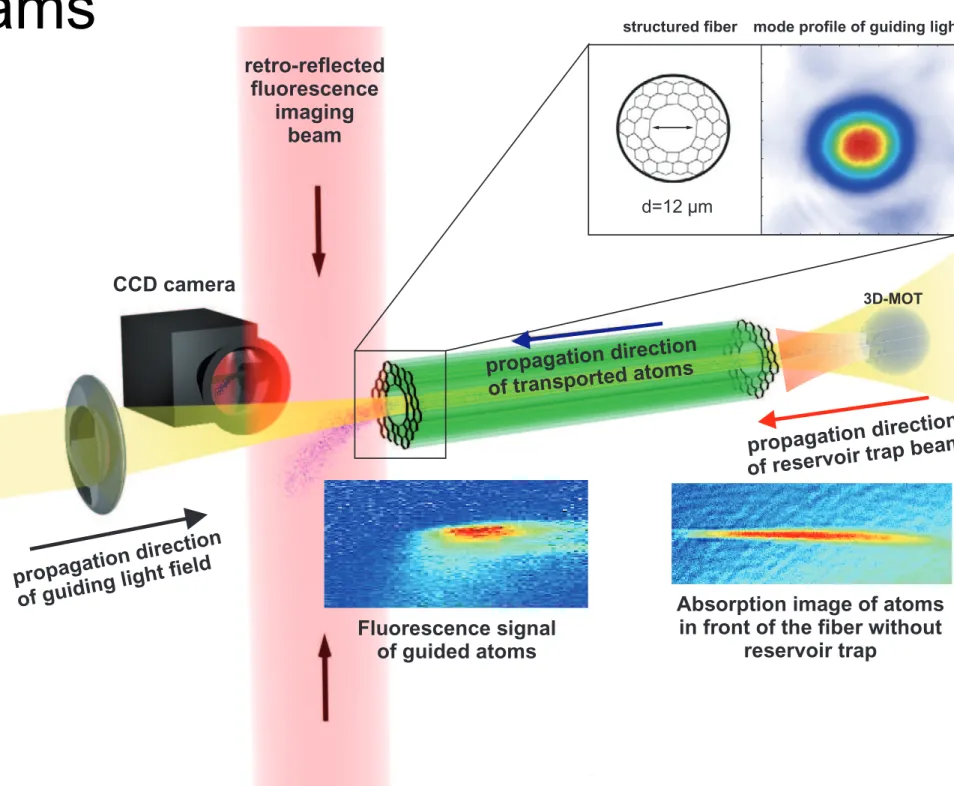
d=12 µm
Fluorescence signal of guided atoms
Absorption image of atoms in front of the fiber without
reservoir trap retro-reflected
fluorescence imaging
beam
CCD camera
structured fiber mode profile of guiding light
3D-MOT
propagation direction of guiding light field
propagation direction of transported atoms
propagation direction of reservoir trap beam
Figure 1. Schematic drawing of the experimental setup. A cloud of laser-cooled atoms is prepared in front of the photonic band gap fiber and moved into the trapping region of the fiber trap by changing the position of the magneto-optical trap (MOT) with an additional magnetic field. After transport through the fiber, the atoms are detected by fluorescence imaging with a retro-reflected laser beam and collecting the photons with an intensified CCD camera. For optimization purposes, absorption imaging can be performed of the atoms trapped by the guiding light exiting at the atom-input side of the fiber.
on the guiding process itself. This behavior can not yet be explained. In figure 3(a), the guiding potential and the guiding process are further illustrated. With the above parameters, a potential depth of up to 8.2 mK can be obtained. An input guiding light coupling efficiency of over 80%
is achieved by placing the final focusing lens inside the vacuum chamber
4. As the source for the cold atomic sample, we use a three-dimensional (3D) MOT at one end of the HCPBG fiber, which is efficiently loaded with a cold beam from a 2D MOT in a separate vacuum chamber.
By adiabatically ramping up a homogeneous magnetic field during the MOT phase, the cloud is moved close to the fiber tip and, during a subsequent dark spot MOT and a dark spot molasses phase, a density of 1.5 ⇥ 10
11atoms cm
3and a temperature of 10 µK are obtained. These atoms can be efficiently transferred into the guiding potential. After transport through the fiber, the guided atoms are detected on the opposite side by fluorescence imaging. The necessary sensitivity is obtained by using an intensified CCD camera, which integrates the signal for
4
Aspherical lens with focal length 11 mm, numerical aperture 0.25.
New Journal of Physics 12 (2010) 123015 (http://www.njp.org/)
Dipole Guides: Optical Fibres
S. Vorrath, S. A. Möller, P. Windpassinger, K. Bongs, and K. Sengstock New Journal of Physics 12:12 123015 (2010)
- Free space beams - Lattices
- Paintings
- Fibres
• Dipole Traps
- Guides - Lattices - Paintings - Fibres
Dipole
Matter-Wave Guides
Boshier Criteria of Atomtronics
• L oop
• S mooth
• D ynamic
LSD
LSD
LSD
LSD
• Magnetic Fields
- IP-Trap
- Atomic chips - Mini-traps
- Adiabatic
Magnetic
Matter-Wave Guides
Boshier Criteria of Atomtronics
• L oop
• S mooth
• D ynamic
!"##"$% #& '(#)$"
!"#$%&'()* +,-'+ ).#)/&% 011,'22234567893:;< *++
7=>4? 6@>4ABC< @DE8>F 69:@4;C;?DG 5 =654F58F <>:8;9C9:68;4>:=
H8;:9==,+3 "C6@;7?@ 5 I58>96D ;J J5E8>:56>;4 69:@4>K79= :54 E9 7=9F L=9I985C ?8;7H= @5I9 F9I9C;H9F :7=6;< H8;:9==9=,MG0NOG 5
=654F58F H8;:9== @5= 6@9 5FI5465?9 ;J E9>4? 5I5>C5EC9 6; 4;4A
<>:8;69:@4;C;?D C5E;856;8>9=3
P4 ;78 :@>H 685H=G 6@9 685HH>4? H;6946>5C >= H8;F7:9F ED =7H98A H;=>4? 6@9 B9CF ;J 6@9 C>6@;?85H@>: :;4F7:6;8= 2>6@ 5 @;<;A
?949;7=G 9Q69845C E>5= B9CF !13 " P;JJ9RS8>6:@58F H;6946>5C L4;4A T98; B9CF >4 6@9 <>4><7<G 54F K75F856>: F9H94F94:9 :C;=9 6; 6@>=
<>4><7<O >= :89569F 7=>4? 6@9 UVWA=@5H9F :;4F7:6;8 =@;24 >4 D9CC;2 >4 X>?3 ,5Y 6@9 :94685C H586 ;J 6@>= :;4F7:6;8 @5= 5 C94?6@ ;J ,3ZN <<3 X>?789 ,E =@;2= 6@9 <5?496>: H;6946>5C= :89569F ED 6@>=
2>89 2>6@ 5 :788946 ;J !1 ! 0 " J;8 62; F>JJ98946 I5C79= ;J 6@9 9Q69845C E>5= B9CFG !1 ! "#"# ""$"$ L2@989 "# 54F "$ 589 74>6 I9:6;8=O[ L"# ! 1G "$ ! \ ]O 54F L"# ! ,!Z ]G "$ ! NN ]OG :;889A
=H;4F>4? 6; 6@9 62; 9Q689<9 I5C79= 7=9F >4 6@9 9QH98><9463 ^>6@
>4:895=>4? E>5= B9CFG 6@9 685H :94689 <;I9= :C;=98 6; 6@9 =78J5:9G J8;<%1 !++N!< 6;%1 !_1!<3 #@9 H;6946>5C= I58D K75F856>:5CCD 2>6@ 6@9 F>=654:9 J8;< 6@9 685H :94689 J;8 I98D =<5CC F>=654:9=3 P4 6@9
<5>4 H586 ;J 6@9 685HG 6@9 6854=I98=9 F9H94F94:9 :54 E9 5HH8;Q>A
<569CD :@585:698>T9F ED 6@9 ?85F>946 ;J 6@9 2>89 B9CF 56 %13 #@>=
?85F>946 8>=9= ED 5 J5:6;8 ;J -_`J8;< 011 ] :<!,6; _G-11 ] :<!,` J;8 6@9 62; H;6946>5C= >4 6@9 B?7893 #@9 :94685C H586 ;J 6@9 C;4?A
>67F>45C H;6946>5CG ;4 6@9 ;6@98 @54FG :@54?9= I98D C>66C9 2@>C9 >6=
=699H 25CC= ?8;2 @>?@98 2>6@ 685H :;<H89==>;43
#@9 :@>H 6@56 :89569= 6@9=9 H;6946>5C= >= <;7469F J5:9 F;24 >4 5
?C5== :9CC ;J >4498 F><94=>;4= -1"-1",,1 <<Y 6@>= :9CC >= H586 ;J 5 =><HC9 I5:77< =D=69< H7<H9F ED 5 0N C =!,>;4 H7<H 54F 5 =<5CC 6>654>7< =7EC><56;8 LX>?3 0O3 #@9 <5?496>: 685H C>J96><9 >= 7H 6; N =G 2@>:@ >4F>:569= 5 E5:a?8;74F H89==789 >4 6@9 ,1!Z<E58
854?93 #@98<5C 87E>F>7< I5H;78 >= H8;F7:9F J8;< 5 87E>F>7<
F>=H94=98,_3 ^9 ;H98569 >6 56 C;2G :;4=6546G :788946G =; 6@56 6@9 87E>F>7< H586>5C H89==789 89<5>4= C;2 54F 89F7:9= 6@9 <5?496>:
685H C>J96><9 ED C9== 6@54 01b3 c78>4? 6@9 <5?496;A;H6>:5C 685H Ld)#O C;5F>4? H@5=9G 5 -1A^ @5C;?94 89e9:6;8 E7CE >= =2>6:@9F ;4 6; 69<H;858>CD >4:895=9 6@9 87E>F>7< H89==789 ED C>?@6A>4F7:9F F9=;8H6>;4,\3 #@9 d)# C;5F9F >4 6@>= 25D :;465>4= 5E;76 N",1M 56;<= ;J \_%E 5J698 5 C;5F>4? 6><9 ;J -R_ =3
#85H C;5F>4? >= 5 :87:>5C =69H >4 895C>T>4? 5 <5?496>: <>:8;685H3
^9 7=9 6@9 <>88;8Ad)# 69:@4>K79 F9I9C;H9F >4 ;78 ?8;7H 54F F9=:8>E9F >4 F965>C >4 89J= N 54F ,+3 #@>= I58>546 ;J 6@9 29CCAa4;24 d)# H8;I>F9= 5 =5<HC9 ;J C5=98A:;;C9F 56;<= 56 5 F>=654:9 ;J C9==
6@54 , << J8;< 6@9 =7E=68569 =78J5:9G 54F 945EC9= &' (&)* 6854=J98
>46; 6@9 <5?496>: <>:8;685H 2>6@;76 89K7>8>4? 54 >4698<9F>569G
<5:8;=:;H>: <5?496>: 685H3 P4 6@>= 25D 29 6DH>:5CCD C;5F -",1M 56;<= >46; 6@9 <5?496>: 685H 5J698 ;H6>:5C H7<H>4? >46; 6@9 + ! 0G ,X ! 0 ?8;74F =65693
#@9 >4>6>5C <5?496>: 685HH>4? H;6946>5C >= =@;24 >4 F5=@9F C>49=
>4 X>?3 ,E3 #@>= 685H @5= J89K794:>9= !# ! 0\ fT 54F !$"% ! 001 fT3
#@9 69<H9856789 54F H95a F94=>6DG <95=789F 011 <= 5J698 6854=J98 J8;< 6@9 d)#G 589 !+N!g 54F !N",1,1:<#-G 89=H9:6>I9CD3 P<<9F>569CD 5J698 6@9 6854=J98G 29 >4:895=9 6@9 E>5= B9CF "$ >4 -11 <= 6; 5 B45C I5C79 ;J NN ]G C95F>4? 6; 6@9 H;6946>5C =@;24 >4
=;C>F C>49= >4 X>?3 ,E3 #@7=G =68;4? :;<H89==>;4 ;::78= >4 6@9 6854=I98=9 L$G%O HC549G 2@9895= 6@9 C;4?>67F>45C H;6946>5C 74F98?;9=
5 :;<H5856>I9CD =<5CC :@54?93 #@9 I98D 54>=;68;H>: B45C H;6946>5C
@5= 5 6854=I98=9 :78I56789 ;J 0!+",1_ ] :<#0 4958 6@9 :94689G C95F>4? 6; 5 :5C:7C569F 6854=I98=9 ;=:>CC56>;4 J89K794:D ;J
!$"% ! M!0 afTG 2@>C9 6@9 C;4?>67F>45C J89K794:D >= ;4CD
!# ! ,_ fT3 &QH98><9465CCDG 29 @5I9 7=9F 62; F>JJ98946 69:@4>K79=
LF>89:6 ;E=98I56>;4 ;J 6@9 ;=:>CC56>;4 54F H585<968>: @956>4?O 6;
<95=789 6@9=9 J89K794:>9=G 54F J;74F ?;;F 5?899<946 ;J :5C:7C569F 54F <95=789F J89K794:>9=3
P<<9F>569CD 5J698 :;<H89==>;4G 29 >4>6>569 J;8:9F 9I5H;856>I9 :;;C>4? 2>6@ 5 C>4958 85F>;AJ89K794:D =299H J8;< -1 dfT 6;
\ dfT3 #@>= =299H >= 6DH>:5CCD H98J;8<9F >4 Z11 <=G 54F 89F7:9=
6@9 47<E98 ;J 56;<= 6; N",1N3 X8;< @989G 29 :54 H8;:99F 6; /&.
ED 62; F>JJ98946 8;769=G E;6@ ;J 2@>:@ >4I;CI9 54 5F>5E56>: :@54?9 >4 6@9 H;6946>5C3 P4 6@9 B8=6 :5=9G 6@9 685H >= =><HCD F9:;<H89==9F ED 89F7:>4?!1`C95F>4? 6; 5 I98D 9C;4?569F :;4F94=569 :94689F 56 6@9 H;=>6>;4 ., >4 X>?3 ,53 P4 6@9 =9:;4F 5HH8;5:@G 6@9 2>89 :788946= 589
z (mm) x (mm)
1
0 2
10 60
B (G)
–1 0 1
10 60
B (G)
I0 IM1
I0 I1
IQ IM2
I1 1.95 mm
a
b
C1 C2
x y
18.4 mm
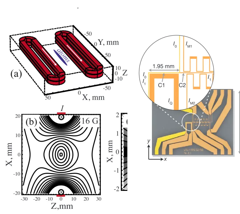
!"#$%& '!"# $"%& '() *"# +',(#*%$ &-*#(*%'./ *"'* %* $0#'*#/1(2 3'4-5* -6 *"# .%*"-,0'&"%$
,-.) 7%0#/ -( *"# /58/*0'*#1 !"# %(/#* /"-7/ *"# 0#.#9'(* &'0* -6 *"# $-()5$*-0 &'**#0(1!:2
!;2!<;'()!<=$0#'*# *"# 9'0%-5/ +',(#*%$ &-*#(*%'./ 6-0 *0'&&%(, >/##)? '() *0'(/&-0*2 '/
)#/$0%8#) %( *"# +'%( *#@*2!A%/ 5/#) -(.4 )50%(, *0'& .-')%(, >%(*#0+#)%'*# <B! /*#&C?1 )2 D-*#(*%'./ $0#'*#) 84 ' 7%0# $500#(*!: != E 6-0 *7- )%66#0#(* 9'.5#/ -6 *"# #@*#0('.
8%'/ F#.)2 >"# ! :2"$ ! G H? >)'/"#) .%(#/? '() >"# !;!I H2"$ ! CC H? >/-.%) .%(#/?1
To pumps
Substrate (upside down)
Copper block Rubidium dispenser
Glass cell Electrical feedthrough
!"#$%& *J'$55+ /4/*#+1 K#$'5/# -6 *"# #6F$%#(* #9'&-0'*%-( %( *"# $"%& *0'&2 *"%/ 9#04 /%+&.# /#*L5& %/ /56F$%#(* *- '$"%#9# K-/#MN%(/*#%( $-()#(/'*%-( >KNO?1 !"# /58/*0'*# %/
+-5(*#) 6'$%(, )-7(7'0)/2 /- *"'* *"# '*-+ $.-5) +'4 8# 0#.#'/#) *- #@&'() %( 60## 6'..
>*%+#L-6LP%,"* '('.4/%/?1
© 2001 Macmillan Magazines Ltd
the device. The magnetic guide can be transported by mov- ing the guiding structure
21but the constraints on the physical motion are substantial; therefore, it is desirable to keep the position of the guiding structure fixed while translating the position of the guiding potential by using time-dependent currents. Chip-based geometries using 50 ! m scale wires are capable of transporting atom microtraps over mm distance
22and can potentially achieve smooth cm scale trans- lations of atom guides.
23Here we investigate the coherence properties of an atom interferometer whose guiding potential is generated by macroscopic current coils that allow a smooth translation of the guided atoms over distances ex- ceeding 5 mm. If used for translation in a multiple-conductor design ! instead of two " , the symmetric guide would not com- promise smooth translation of atoms because symmetry as- sures that zero field position does not move from one con- ductor to another ! even in gaps " while wiring coils in series assures that the guide position is exactly in the symmetry axis.
II. MAGNETIC GUIDE DESCRIPTION
The guiding structure developed here is based on race- track coils with macroscopic copper tape ! bridgeport mag- netics " wrapped around aluminum structures as shown in
Fig. 1 ! a " . Such a guide allows dynamical cancellation of
magnetic field and provides in situ loading into a surface magneto-optical trap ! MOT " . It is easily fabricated and does not require water cooling to generate large field gradients.
Each coil has a 150 " 15 mm
2aluminum core and consists of N =29 turns of double conductor tape ! 6.35 mm wide and 0.25 mm thick " with a 0.025-mm-thick layer of Kapton in- sulator on one side. The spacing between two coils 2h can be varied to accommodate vacuum cells of different sizes. We enclose each coil in glass-epoxy dielectric retainers to ensure that the coils are straight and parallel to each other. In the
experiment, we place the guiding structure outside of an ul- trahigh vacuum glass cell with square ! 4 " 4 cm
2" cross- section. The guide is mounted on two translational and two rotational stages that allow initial alignment of the guide axis with respect to the optical beams. In the stationary guide regime we use only one set of conductors from each coil, which are connected in series. Open air provides enough heat dissipation for the applied current of up to 50 A in the pulsed current regime with a typical duty cycle of up to 45%.
In our setup the quadrupole guiding potential is created along the symmetry axis between coils 2 cm away from the outer turn of each coil. A peak current I =50 A in the guiding regime provides a field gradient of 80 G/cm and a guide depth of # 2.7 mK for the $ F =1, m
F= −1 % ground state of
87
Rb & see Fig. 1 ! c "' . The transverse magnetic field to the
lowest order about the symmetry axis can be written as:
B !
!! x, z " # b
0( 2z ) h 1
2− ! h + 1 $ "
2* x ˆ
+ 2x ) ! h + 1 $ "
2+ 1
h
2* z ˆ + , ! 1 "
where $ is the effective width of the aluminum core in each electromagnet, b
0is a constant, which is a function of the number of turns in each coil N, the width of the conductor tape w, and is proportional to current I. In our design we set
$ # h to optimize the field gradient and potential depth, while keeping relatively compact the design of the structure.
From Eq. ! 1 " , the magnetic field and radial gradient of the field at a small displacement from the symmetry axis scale with coils separation as #1 / h
2. Microscopic separation of the coils can provide field gradients of the order of a few ki- logauss per centimeter, which can be beneficial for some applications.
24The major advantage of our design is the sup- pressed longitudinal curvature of the field. The curved poten- tials from the top and bottom conductors due to the finite size of each coil have equal value and opposite sign curvatures and therefore cancel in the symmetry axis. Figure 1 ! d " shows the contour plot of the magnetic field along the guiding axis.
The divergence of the equipotential lines due to the edges at a small displacement from the symmetry axis is less than 0.3 mrad and orders of magnitude less than that if we only con- sider the central 50% of the guide length. If we take into account the desired radial dimension of the guided atoms of 2 % # 200 ! m and its lateral dimension of 1 cm ! ultimately limited by the size of the glass cell " then the divergence caused by the guiding potential is much lower than the typi- cal accepted limit of 0.1–0.3 mrad in a so-called “quantum freeze” regime,
25where the longitudinal excitation does not couple to the transverse direction.
As a comparison, we performed calculation of the field of the similar size macroscopic guide in conventional counter-propagating current geometry ! see Fig. 2 " . Such a conventional “atom-chip” design provides atom confinement close to the chip surface ! in our case at a height of 10.4 mm " . The contour plot of the field along the guiding axis, as shown in Fig. 2 ! b " , gives the harmonic shape of the potential with the field lines divergence of # 20 mrad, which is several orders of magnitude more than the curvature of the same size (c)
-30 -20 -10 0 10 20 30
Z,mm
-20 -10 0 10 20
X, mm
0 -50
50
X, mm
-50 0
50
Y, mm
-10010
Z
(a)
x
x
(b) 16 G
Z, mm
B, G
I
atoms
-60 -40 -20 0 20 40 60
Y, mm
-2 -1 0 1 2
X, m m
1.6 G
(d)
FIG. 1. ! Color online " Symmetric guide configuration ! a " , and numerically calculated magnetic field of the guide for current of 50 A; ! b " contour plot of the magnetic field vs position ! x , z " ! the separation between the lines is 16 G, the tape conductors from two coils and direction of the current are shown for the reference " ; ! c " magnetic field vs x; ! d " contour plot of the magnetic field vs long axis y ! black color represents zero of the field, the separation between the equipotential lines is 1.6 G " .
094904-2 A. Tonyushkin and M. Prentiss J. Appl. Phys. 108, 094904 !2010"
Downloaded 17 May 2011 to 139.91.197.113. Redistribution subject to AIP license or copyright; see http://jap.aip.org/about/rights_and_permissions
Magnetic Guides
• Magnetic Fields
- IP-Trap
- Atomic chips - Mini-traps
- TAAPs
Alexey Tonyushkin and Mara Prentiss Journal of Applied Physics 108:9 094904 (2010)
!"##"$% #& '(#)$"
!"#$%&'()* +,-'+ ).#)/&% 011,'22234567893:;< *++
7=>4? 6@>4ABC< @DE8>F 69:@4;C;?DG 5 =654F58F <>:8;9C9:68;4>:=
H8;:9==,+3 "C6@;7?@ 5 I58>96D ;J J5E8>:56>;4 69:@4>K79= :54 E9 7=9F L=9I985C ?8;7H= @5I9 F9I9C;H9F :7=6;< H8;:9==9=,MG0NOG 5
=654F58F H8;:9== @5= 6@9 5FI5465?9 ;J E9>4? 5I5>C5EC9 6; 4;4A
<>:8;69:@4;C;?D C5E;856;8>9=3
P4 ;78 :@>H 685H=G 6@9 685HH>4? H;6946>5C >= H8;F7:9F ED =7H98A H;=>4? 6@9 B9CF ;J 6@9 C>6@;?85H@>: :;4F7:6;8= 2>6@ 5 @;<;A
?949;7=G 9Q69845C E>5= B9CF !13 " P;JJ9RS8>6:@58F H;6946>5C L4;4A T98; B9CF >4 6@9 <>4><7<G 54F K75F856>: F9H94F94:9 :C;=9 6; 6@>=
<>4><7<O >= :89569F 7=>4? 6@9 UVWA=@5H9F :;4F7:6;8 =@;24 >4 D9CC;2 >4 X>?3 ,5Y 6@9 :94685C H586 ;J 6@>= :;4F7:6;8 @5= 5 C94?6@ ;J ,3ZN <<3 X>?789 ,E =@;2= 6@9 <5?496>: H;6946>5C= :89569F ED 6@>=
2>89 2>6@ 5 :788946 ;J !1 ! 0 " J;8 62; F>JJ98946 I5C79= ;J 6@9 9Q69845C E>5= B9CFG !1 ! "#"# ""$"$ L2@989 "# 54F "$ 589 74>6 I9:6;8=O[ L"# ! 1G "$ ! \ ]O 54F L"# ! ,!Z ]G "$ ! NN ]OG :;889A
=H;4F>4? 6; 6@9 62; 9Q689<9 I5C79= 7=9F >4 6@9 9QH98><9463 ^>6@
>4:895=>4? E>5= B9CFG 6@9 685H :94689 <;I9= :C;=98 6; 6@9 =78J5:9G J8;<%1 !++N!< 6;%1 !_1!<3 #@9 H;6946>5C= I58D K75F856>:5CCD 2>6@ 6@9 F>=654:9 J8;< 6@9 685H :94689 J;8 I98D =<5CC F>=654:9=3 P4 6@9
<5>4 H586 ;J 6@9 685HG 6@9 6854=I98=9 F9H94F94:9 :54 E9 5HH8;Q>A
<569CD :@585:698>T9F ED 6@9 ?85F>946 ;J 6@9 2>89 B9CF 56 %13 #@>=
?85F>946 8>=9= ED 5 J5:6;8 ;J -_`J8;< 011 ] :<!,6; _G-11 ] :<!,` J;8 6@9 62; H;6946>5C= >4 6@9 B?7893 #@9 :94685C H586 ;J 6@9 C;4?A
>67F>45C H;6946>5CG ;4 6@9 ;6@98 @54FG :@54?9= I98D C>66C9 2@>C9 >6=
=699H 25CC= ?8;2 @>?@98 2>6@ 685H :;<H89==>;43
#@9 :@>H 6@56 :89569= 6@9=9 H;6946>5C= >= <;7469F J5:9 F;24 >4 5
?C5== :9CC ;J >4498 F><94=>;4= -1"-1",,1 <<Y 6@>= :9CC >= H586 ;J 5 =><HC9 I5:77< =D=69< H7<H9F ED 5 0N C =!,>;4 H7<H 54F 5 =<5CC 6>654>7< =7EC><56;8 LX>?3 0O3 #@9 <5?496>: 685H C>J96><9 >= 7H 6; N =G 2@>:@ >4F>:569= 5 E5:a?8;74F H89==789 >4 6@9 ,1!Z<E58
854?93 #@98<5C 87E>F>7< I5H;78 >= H8;F7:9F J8;< 5 87E>F>7<
F>=H94=98,_3 ^9 ;H98569 >6 56 C;2G :;4=6546G :788946G =; 6@56 6@9 87E>F>7< H586>5C H89==789 89<5>4= C;2 54F 89F7:9= 6@9 <5?496>:
685H C>J96><9 ED C9== 6@54 01b3 c78>4? 6@9 <5?496;A;H6>:5C 685H Ld)#O C;5F>4? H@5=9G 5 -1A^ @5C;?94 89e9:6;8 E7CE >= =2>6:@9F ;4 6; 69<H;858>CD >4:895=9 6@9 87E>F>7< H89==789 ED C>?@6A>4F7:9F F9=;8H6>;4,\3 #@9 d)# C;5F9F >4 6@>= 25D :;465>4= 5E;76 N",1M 56;<= ;J \_%E 5J698 5 C;5F>4? 6><9 ;J -R_ =3
#85H C;5F>4? >= 5 :87:>5C =69H >4 895C>T>4? 5 <5?496>: <>:8;685H3
^9 7=9 6@9 <>88;8Ad)# 69:@4>K79 F9I9C;H9F >4 ;78 ?8;7H 54F F9=:8>E9F >4 F965>C >4 89J= N 54F ,+3 #@>= I58>546 ;J 6@9 29CCAa4;24 d)# H8;I>F9= 5 =5<HC9 ;J C5=98A:;;C9F 56;<= 56 5 F>=654:9 ;J C9==
6@54 , << J8;< 6@9 =7E=68569 =78J5:9G 54F 945EC9= &' (&)* 6854=J98
>46; 6@9 <5?496>: <>:8;685H 2>6@;76 89K7>8>4? 54 >4698<9F>569G
<5:8;=:;H>: <5?496>: 685H3 P4 6@>= 25D 29 6DH>:5CCD C;5F -",1M 56;<= >46; 6@9 <5?496>: 685H 5J698 ;H6>:5C H7<H>4? >46; 6@9 + ! 0G ,X ! 0 ?8;74F =65693
#@9 >4>6>5C <5?496>: 685HH>4? H;6946>5C >= =@;24 >4 F5=@9F C>49=
>4 X>?3 ,E3 #@>= 685H @5= J89K794:>9= !# ! 0\ fT 54F !$"% ! 001 fT3
#@9 69<H9856789 54F H95a F94=>6DG <95=789F 011 <= 5J698 6854=J98 J8;< 6@9 d)#G 589 !+N!g 54F !N",1,1:<#-G 89=H9:6>I9CD3 P<<9F>569CD 5J698 6@9 6854=J98G 29 >4:895=9 6@9 E>5= B9CF "$ >4 -11 <= 6; 5 B45C I5C79 ;J NN ]G C95F>4? 6; 6@9 H;6946>5C =@;24 >4
=;C>F C>49= >4 X>?3 ,E3 #@7=G =68;4? :;<H89==>;4 ;::78= >4 6@9 6854=I98=9 L$G%O HC549G 2@9895= 6@9 C;4?>67F>45C H;6946>5C 74F98?;9=
5 :;<H5856>I9CD =<5CC :@54?93 #@9 I98D 54>=;68;H>: B45C H;6946>5C
@5= 5 6854=I98=9 :78I56789 ;J 0!+",1_ ] :<#0 4958 6@9 :94689G C95F>4? 6; 5 :5C:7C569F 6854=I98=9 ;=:>CC56>;4 J89K794:D ;J
!$"% ! M!0 afTG 2@>C9 6@9 C;4?>67F>45C J89K794:D >= ;4CD
!# ! ,_ fT3 &QH98><9465CCDG 29 @5I9 7=9F 62; F>JJ98946 69:@4>K79=
LF>89:6 ;E=98I56>;4 ;J 6@9 ;=:>CC56>;4 54F H585<968>: @956>4?O 6;
<95=789 6@9=9 J89K794:>9=G 54F J;74F ?;;F 5?899<946 ;J :5C:7C569F 54F <95=789F J89K794:>9=3
P<<9F>569CD 5J698 :;<H89==>;4G 29 >4>6>569 J;8:9F 9I5H;856>I9 :;;C>4? 2>6@ 5 C>4958 85F>;AJ89K794:D =299H J8;< -1 dfT 6;
\ dfT3 #@>= =299H >= 6DH>:5CCD H98J;8<9F >4 Z11 <=G 54F 89F7:9=
6@9 47<E98 ;J 56;<= 6; N",1N3 X8;< @989G 29 :54 H8;:99F 6; /&.
ED 62; F>JJ98946 8;769=G E;6@ ;J 2@>:@ >4I;CI9 54 5F>5E56>: :@54?9 >4 6@9 H;6946>5C3 P4 6@9 B8=6 :5=9G 6@9 685H >= =><HCD F9:;<H89==9F ED 89F7:>4?!1`C95F>4? 6; 5 I98D 9C;4?569F :;4F94=569 :94689F 56 6@9 H;=>6>;4 ., >4 X>?3 ,53 P4 6@9 =9:;4F 5HH8;5:@G 6@9 2>89 :788946= 589
z (mm) x (mm)
1
0 2
10 60
B (G)
–1 0 1
10 60
B (G)
I0 IM1
I0 I1
IQ IM2
I1 1.95 mm
a
b
C1 C2
x y
18.4 mm
!"#$%& '!"# $"%& '() *"# +',(#*%$ &-*#(*%'./ *"'* %* $0#'*#/1(2 3'4-5* -6 *"# .%*"-,0'&"%$
,-.) 7%0#/ -( *"# /58/*0'*#1 !"# %(/#* /"-7/ *"# 0#.#9'(* &'0* -6 *"# $-()5$*-0 &'**#0(1!:2
!;2!<;'()!<=$0#'*# *"# 9'0%-5/ +',(#*%$ &-*#(*%'./ 6-0 *0'&&%(, >/##)? '() *0'(/&-0*2 '/
)#/$0%8#) %( *"# +'%( *#@*2!A%/ 5/#) -(.4 )50%(, *0'& .-')%(, >%(*#0+#)%'*# <B! /*#&C?1 )2 D-*#(*%'./ $0#'*#) 84 ' 7%0# $500#(*!: != E 6-0 *7- )%66#0#(* 9'.5#/ -6 *"# #@*#0('.
8%'/ F#.)2 >"# ! :2"$ ! G H? >)'/"#) .%(#/? '() >"# !;!I H2"$ ! CC H? >/-.%) .%(#/?1
To pumps
Substrate (upside down)
Copper block Rubidium dispenser
Glass cell Electrical feedthrough
!"#$%& *J'$55+ /4/*#+1 K#$'5/# -6 *"# #6F$%#(* #9'&-0'*%-( %( *"# $"%& *0'&2 *"%/ 9#04 /%+&.# /#*L5& %/ /56F$%#(* *- '$"%#9# K-/#MN%(/*#%( $-()#(/'*%-( >KNO?1 !"# /58/*0'*# %/
+-5(*#) 6'$%(, )-7(7'0)/2 /- *"'* *"# '*-+ $.-5) +'4 8# 0#.#'/#) *- #@&'() %( 60## 6'..
>*%+#L-6LP%,"* '('.4/%/?1
© 2001 Macmillan Magazines Ltd
the device. The magnetic guide can be transported by mov- ing the guiding structure
21but the constraints on the physical motion are substantial; therefore, it is desirable to keep the position of the guiding structure fixed while translating the position of the guiding potential by using time-dependent currents. Chip-based geometries using 50 ! m scale wires are capable of transporting atom microtraps over mm distance
22and can potentially achieve smooth cm scale trans- lations of atom guides.
23Here we investigate the coherence properties of an atom interferometer whose guiding potential is generated by macroscopic current coils that allow a smooth translation of the guided atoms over distances ex- ceeding 5 mm. If used for translation in a multiple-conductor design ! instead of two " , the symmetric guide would not com- promise smooth translation of atoms because symmetry as- sures that zero field position does not move from one con- ductor to another ! even in gaps " while wiring coils in series assures that the guide position is exactly in the symmetry axis.
II. MAGNETIC GUIDE DESCRIPTION
The guiding structure developed here is based on race- track coils with macroscopic copper tape ! bridgeport mag- netics " wrapped around aluminum structures as shown in
Fig. 1 ! a " . Such a guide allows dynamical cancellation of
magnetic field and provides in situ loading into a surface magneto-optical trap ! MOT " . It is easily fabricated and does not require water cooling to generate large field gradients.
Each coil has a 150 " 15 mm
2aluminum core and consists of N =29 turns of double conductor tape ! 6.35 mm wide and 0.25 mm thick " with a 0.025-mm-thick layer of Kapton in- sulator on one side. The spacing between two coils 2h can be varied to accommodate vacuum cells of different sizes. We enclose each coil in glass-epoxy dielectric retainers to ensure that the coils are straight and parallel to each other. In the
experiment, we place the guiding structure outside of an ul- trahigh vacuum glass cell with square ! 4 " 4 cm
2" cross- section. The guide is mounted on two translational and two rotational stages that allow initial alignment of the guide axis with respect to the optical beams. In the stationary guide regime we use only one set of conductors from each coil, which are connected in series. Open air provides enough heat dissipation for the applied current of up to 50 A in the pulsed current regime with a typical duty cycle of up to 45%.
In our setup the quadrupole guiding potential is created along the symmetry axis between coils 2 cm away from the outer turn of each coil. A peak current I =50 A in the guiding regime provides a field gradient of 80 G/cm and a guide depth of # 2.7 mK for the $ F =1, m
F= −1 % ground state of
87
Rb & see Fig. 1 ! c "' . The transverse magnetic field to the
lowest order about the symmetry axis can be written as:
B !
!! x, z " # b
0( 2z ) h 1
2− ! h + 1 $ "
2* x ˆ
+ 2x ) ! h + 1 $ "
2+ 1
h
2* z ˆ + , ! 1 "
where $ is the effective width of the aluminum core in each electromagnet, b
0is a constant, which is a function of the number of turns in each coil N, the width of the conductor tape w, and is proportional to current I. In our design we set
$ # h to optimize the field gradient and potential depth, while keeping relatively compact the design of the structure.
From Eq. ! 1 " , the magnetic field and radial gradient of the field at a small displacement from the symmetry axis scale with coils separation as #1 / h
2. Microscopic separation of the coils can provide field gradients of the order of a few ki- logauss per centimeter, which can be beneficial for some applications.
24The major advantage of our design is the sup- pressed longitudinal curvature of the field. The curved poten- tials from the top and bottom conductors due to the finite size of each coil have equal value and opposite sign curvatures and therefore cancel in the symmetry axis. Figure 1 ! d " shows the contour plot of the magnetic field along the guiding axis.
The divergence of the equipotential lines due to the edges at a small displacement from the symmetry axis is less than 0.3 mrad and orders of magnitude less than that if we only con- sider the central 50% of the guide length. If we take into account the desired radial dimension of the guided atoms of 2 % # 200 ! m and its lateral dimension of 1 cm ! ultimately limited by the size of the glass cell " then the divergence caused by the guiding potential is much lower than the typi- cal accepted limit of 0.1–0.3 mrad in a so-called “quantum freeze” regime,
25where the longitudinal excitation does not couple to the transverse direction.
As a comparison, we performed calculation of the field of the similar size macroscopic guide in conventional counter-propagating current geometry ! see Fig. 2 " . Such a conventional “atom-chip” design provides atom confinement close to the chip surface ! in our case at a height of 10.4 mm " . The contour plot of the field along the guiding axis, as shown in Fig. 2 ! b " , gives the harmonic shape of the potential with the field lines divergence of # 20 mrad, which is several orders of magnitude more than the curvature of the same size (c)
-30 -20 -10 0 10 20 30
Z,mm
-20 -10 0 10 20
X, mm
0 -50
50
X, mm
-50 0
50
Y, mm
-10010
Z
(a)
x
x
(b) 16 G
Z, mm
B, G
I
atoms
-60 -40 -20 0 20 40 60
Y, mm
-2 -1 0 1 2
X, m m
1.6 G
(d)
FIG. 1. ! Color online " Symmetric guide configuration ! a " , and numerically calculated magnetic field of the guide for current of 50 A; ! b " contour plot of the magnetic field vs position ! x , z " ! the separation between the lines is 16 G, the tape conductors from two coils and direction of the current are shown for the reference " ; ! c " magnetic field vs x; ! d " contour plot of the magnetic field vs long axis y ! black color represents zero of the field, the separation between the equipotential lines is 1.6 G " .
094904-2 A. Tonyushkin and M. Prentiss J. Appl. Phys. 108, 094904 !2010"
Downloaded 17 May 2011 to 139.91.197.113. Redistribution subject to AIP license or copyright; see http://jap.aip.org/about/rights_and_permissions
Magnetic Guides
• M

![FIG. 1. (Color online) Fringe visibility for various LMT ac- ac-celerometer experiments [5–13] as measured by the peak-to-peak amplitude of a sinusoidal fit to each fringe set](https://thumb-us.123doks.com/thumbv2/123dok_es/12537686.0/18.1536.162.758.622.1060/fringe-visibility-various-celerometer-experiments-measured-amplitude-sinusoidal.webp)