JOURNAL OF MARITIME RESEARCHVOL.VI No2 AUGUST 2009
G. Oliver
AUTOMAR NETWORK
B. Garau, M. Bonet, A. Alvarez, S. Ruiz and A. Pascual
PATH PLANNING FOR AUTONOMOUS UNDERWATER VEHICLES IN REALISTIC OCEANIC CURRENT FIELDS: APPLICATION TO GLIDERS IN THE WESTERN MEDITERRANEAN SEA
S. Gomariz, J. Prat, P. Gaya and J. Sole
AN AUTONOMOUS VEHICLE DEVELOPMENT FOR SUBMARINE OBSERVATION
O. Calvo, A. Sousa, J. Bibiloni, H. Curti, G. Acosta and A. Rozenfeld LOW-COST AUTONOMOUS UNDERWATER VEHICLE FOR UNDERWATER ACOUSTIC INSPECTIONS
R. Ferreiro, R. Haro and J.L. Calvo
ON SENSOR FDI BY FUNCTIONAL AND PHYSICAL REDUNDANCY APPLIED TO DP SYSTEMS
D. Moreno, D. Chaos, J. Aranda, R. Muñoz, J. M. Díaz and S. Dormido-Canto
APPLICATION OF AN AERONAUTIC CONTROL FOR SHIP PATH FOLLOWING
A. Ortiz and J. Antich
BAYESIAN VISUAL TRACKING FOR INSPECTION OF UNDERSEA POWER AND TELECOMMUNICATION CABLES
VOL.VI N o 2
Carlos A. Pérez Labajos Editor
Amable López Piñeiro Assistant Editor Alberto Pigazo López Associate Editor Ana Alegría de la Colina Marlén Izquierdo Fernández Kenneth Friedman Sean Scurfield Gema Diego Hazas Language Revision Committee Antonio Trueba Cortés Andrés Ortega Piris Navigation
Francisco Correa Ruiz Máximo Azofra Colina Diana Díaz Guazo Marine Safety
Francisco J. Velasco González Automation in Marine Systems Beatriz Blanco Rojo José R. San Cristobal Shipping Business Julio Barros Guadalupe Víctor M. Moreno Sáiz Alberto Pigazo López Ramón I. Diego García Electronic and Electrical Systems
EDITORIAL BOARD University of the Basque Country Fernando Cayuela Camarero Escuela Técnica Superior de Náutica y Máquinas Navales
Miguel Ángel Gomez Solaetxe Dep. de Ciencias y Técnicas de la Navegación, Máquinas y Construcciones Navales
University of Cantabria Carlos A. Pérez-Labajos Escuela Técnica Superior de Náutica Félix M. Otero González Dep. de Ciencias y Técnicas de la Navegación y de la Construcción Naval
University of Oviedo Rafael García Méndez Escuela Superior de la Marina Civil Daniel Ponte Gutiérrez Dpto. de Ciencia y Tecnología Náutica
University of La Coruña Álvaro Baaliña Insúa
Escuela Técnica Superior de Náutica y Máquinas José A. Orosa García
Dep. de Energía y Propulsión Marina Santiago Iglesias Boniela Dep. de Ciencias de la Navegación y de la Tierra
University of Cádiz Juan Moreno Gutiérrez Facultad de Ciencias Náuticas Francisco Piniella Corbacho Dep. de Ciencias y Técnicas de la Navegación y Teoría de la Señal y Comunicaciones
The Polytechnic University of Catalonia Ricard Mari Sagarra Facultad de Náutica
Ricard Rodríguez Martos Dauer Dep. de Ciencia e Ingeniería Náuticas
University of La Laguna Alexis Dionis Melian
E.T. S. de Náutica, Máquinas y Radioelectrónica Naval Isidro Padrón Armas
Dep. de Ciencias y Técnicas de la Navegación Pedro Rivero Rodríguez Dep. de Ingeniería Marítima UNIVERSITY OF CANTABRIA
Escuela Técnica Superior de Náutica c/ Gamazo nº1, 39004 SANTANDER Telfno (942) 201362; Fax (942) 201303 e-mail: [email protected]
http://www.jmr.unican.es Layout:JMR
Printed bay: Gráficas Fisa, S.L.
ISSN:1697-4840 D. Legal: SA-368-2004
C
C O O N N T T E E N N T T S S
Automar network
G. Oliver 3
Path Planning for Autonomous Underwater Vehicles in Realistic Oceanic Current Fields: Application to Gliders in the Western Mediterranean Sea
B. Garau, M. Bonet, A. Alvarez, S. Ruiz and A. Pascual 5
An Autonomous Vehicle Development for Submarine Observation
S. Gomariz, J. Prat, P. Gaya and J. Sole 23
Low-cost Autonomous Underwater Vehicle for underwater Acoustic Inspections
O. Calvo, A. Sousa, J. Bibiloni, H. Curti, G. Acosta and A. Rozenfeld 37
On Sensor FDI by Functional and Physical Redundancy Applied to DP Systems
R. Ferreiro, R. Haro and J.L. Calvo 53
Application of an Aeronautic Control for Ship Path Following
D. Moreno, D. Chaos, J. Aranda, R. Muñoz, J. M. Díaz
and S. Dormido-Canto 71
Bayesian Visual Tracking for Inspection of Undersea Power and Telecommunication Cables
A. Ortiz and J. Antich 83
Automar Scientific Committee
Gabriel Oliver (UIB) Manel Frigola (UPC) Rafael García (UdG) Yolanda González (UIB)
Pablo González de Santos (IAI-CSIC) Antoni Mánuel (SARTI/UPC)
Jaume Piera (UTM-CSIC) Pere Ridao (UdG)
Roque Saltarén (UPM)
Carlos Silvestre (IST)
Francisco Velasco (UC)
Automar is a research network in auto- matic control and robotics for the ma- rine industry and marine sciences. Au- tomar brings together scholars from universities and research centres, en- couraging knowledge exchange, train- ing and cooperation among the different members of the scientific and industrial community. To that end, the members of the network organize scientific and technical meetings, courses, tutorials and conferences on a regular basis.
Since its initial steps in 2002, Au- tomar has organized more than ten events, promoting scientific education or cooperation and disseminating know-how among its partners, indus- trial companies and marine technology end-users. Throughout that time, the size of the network has progressively ex- panded to include more than fifteen re- search groups.
In September 2008, around forty re- searchers and students attended the Jor- nadas Automar, a three-day event held at the Universitat de les Illes Balears campus, in Palma (Spain). The first day Prof. Car- los F. Silvestre, from the Instituto Superior Técnicoof Lisbon, conducted a tutorial about the design of tracking controllers for unmanned vehicles. During the sec- ond and third days, both researchers and PhD students presented twenty-one re- search and development projects.
In this issue, the reader will find some of the research works presented during the above-mentioned Automar meeting. The original manuscripts of the selected papers were extended and adapted to meet the JMR publication guidelines. They were additionally re- viewed by an ad-hoc technical commit- tee. As a matter of fact, the present selec- tion does not intend to cover all the top-
Some of the participants of the Jornadas Automar 2008
Automar network
ics in marine robotics and automation.
Still, it can be considered representative of Automar partners’ activity.
Four papers focus on AUV design and applications, probably one of the more dynamic and challenging areas at the moment. Sousa et al. present the de- sign and preliminary results of a low- cost AUV for acoustic inspection. Re- searchers at the Technical University of Catalonia in Vilanova describe an au- tonomous hybrid (surface/underwater) vehicle as a solution for intensive vertical profile logging in oceanographic sys- tems. Gliders are also extensively used in many oceanographic tasks and thus the paper from researchers at IMEDEA- CSIC proposes a path-planning strategy that uses large-scale current fields in- formation to optimize power consump- tion and guarantee the completion of long-term missions with that type of ve- hicles. Ortiz and Antich present a new solution, based on particle filters, for vi- sual vehicle guidance in underwater ca- ble inspection. The article authored by Moreno et al. focuses on the path follow- ing control of an unmanned surface ve- hicle, which is a highly relevant and top-
ical issue in autonomous navigation.
Last but not least, researchers from Uni- versities of A Coruña and Cádiz present a new methodology to ensure sensor fault detection and isolation applied to the thruster equipment of a dynamic positioning control system.
To end with, I would like to thank all the individuals and institutions that made this Special Issue of JMR possi- ble. I remain indebted to all the members of the research groups involved in the Automar network for actively partici- pating in this fruitful experience and to the University of Balearic Islands for hosting the Jornadas. Thanks are also due to the authors for their contribu- tions and to the reviewers for their inter- est and efficient fulfilment of all the re- quirements in the submission process.
Finally, my gratitude goes to people from the Journal of Maritime Research, who have provided us with constant guidance and support.
A special mention should be made to the Spanish Ministry of Education and Science for funding Automar network activities with the project DPI2006- 28345-E.
Gabriel Oliver Codina DPI2006-28435-E Project Leader
PATH PLANNING FOR AUTONOMOUS
UNDERWATER VEHICLES IN REALISTIC OCEANIC CURRENT FIELDS: APPLICATION TO GLIDERS IN THE WESTERN MEDITERRANEAN SEA
B. Garau1*, M. Bonet1, A. Alvarez2, S. Ruiz1and A. Pascual1
Received 22 September 2008; received in revised form 29 September 2008; accepted 15 April 2009
ABSTRACT
Autonomous Underwater Vehicles (AUVs) usually operate in ocean environments characterized by complex spatial variability which can jeopardize their missions. To avoid this, planning safety routes with minimum energy cost is of primary impor- tance. This work revisits the benefits, in terms of travelling time, of path planning in marine environments showing spatial variability. By means of a path planner pre- sented in a previous paper, this work focuses on the application to a real environ- ment of such techniques. Extensive computations have been carried out to calculate optimal paths on realistic ocean environments, based on autonomous underwater glider properties as the mobile platform.
Unlike previous works, the more realistic and applied case of an autonomous underwater glider surveying the Western Mediterranean Sea is considered. Results indicate that substantial energy savings of planned paths compared to straight line trajectories are obtained when the current intensity and the vehicle speed are com- parable. Conversely, the straight line path betwe en starting and ending points can be considered an optimum path when the current speed does not exceed half of the vehicle velocity. In both situations, benefits of path planning seem dependent also on the spatial structure of the current field.
Keywords:path planning, autonomous underwater vehicles, ocean variability.
Journal of Maritime Research, Vol. VI. No. II, pp. 5-22, 2009 Copyright © 2009. SEECMAR
Printed in Santander (Spain). All rights reserved ISSN: 1697-4840
1Instituto Mediterraneo de Estudios Avanzados, Mallorca, Spain.2NATO Undersea Research Centre, La Spezia, Italy. *Corresponding author ([email protected]) IMEDEA (UIB-CSIC). C/Miquel Marques, 2107190, Esporles, Islas Baleares, Spain.
INTRODUCTION
Autonomous underwater vehicles (AUVs) must frequently operate in ocean environments characterized by complex spatial variability (Schmidt and Bovio, 2000). This spatial complexity is induced by the turbulent nature of the ocean, described by the continuous change of a wide range of spatial and time scales. Ener- getic flows induced by tides and topographic perturbations, instabilities and currents induced by local wind effects, are only few examples of ocean variability. This vari- ability can strongly perturb the development of AUVs operations (Galea, 1999). In particular, AUVs usually encounter strong current fields in the marine environment that can jeopardize their missions. Determining and predicting ocean currents is then a fundamental requirement to optimize certain aspects of the AUV’s perform- ance, specifically when vehicles have to operate energy-exhaustive missions in ocean areas characterized by comparatively strong currents. In such cases, it is of primary importance to plan safety routes with minimum energy cost.
Nowadays, several systems can provide an estimation of the existing current field in a certain region. Numerical ocean models can provide nowcasts and forecasts of ocean variability (Holland and McWilliams, 1987). A typical numerical ocean model consists of finite difference equations representing the momentum, heat and salt bal- ance in a determined area. These equations are integrated forward in time to predict the time evolution of the horizontal and vertical structure of the fluid flow as well as the temperature and salinity within the domain, given the wind stresses and buoyancy forcing at the sea surface. Satellites can also provide current fields derived from their observations of the sea level. The procedure consists of merging into one map the sea level anomalies measured by altimetric satellites along their tracks. Current fields can be derived applying the geostrophic assumption on the resulting merged map. Infor- mation of the environmental current field, obtained either from the ocean models or from satellites observations, can be incorporated into existing path finding algorithms to plan safety routes with minimum energy cost (Alvarez and Caiti, 2001).
Traditionally in AUVs, path planning has been related to safety conditions. The path should be devoid of known obstacles or hazardous areas. Different computa- tional methods were employed to plan safety paths for AUVs. Warren (Warren, 1990) used potential field algorithms to solve the path planning problem. The algo- rithm used artificial potential fields applied to the obstacles and goal positions, employing the resulting field to influence the path of the AUV. Graph searching techniques were employed by Carroll et al. (Carroll et al, 1992) for AUV path plan- ning. In this case, a chart or graph is produced showing free space where no collision will occur and forbidden spaces where a collision will occur. Based on this graph, a path is selected by piecing together the free spaces or by tracing around the forbid- den spaces. Techniques such as case-based reasoning (Vasudevan and Ganesan, 1996) and genetic algorithms (Sugihara and Yuh, 1997) have also been applied to the motion planning for underwater robotic vehicles.
Alvarez and Caiti (Alvarez and Caiti, 2002) employed dynamic programming to carry out a systematic simulation study of the energy savings obtained through opti- mal AUV path planning, taking into account the spatial structure of the current velocity field. The study had the objective of putting in relation the spatial scales of the current field variability with the expected energy saving due to the optimized path planning. Results indicated a substantial energy saving, as compared to straight line paths, when ocean eddy structures were greater than one-third of the total cross- ing distance. Finally, the problem of AUV mission planning optimizing the energy cost in ocean environments with real current fields was considered by Alvarez et al.
(Alvarez, Caiti and Onken, 2004). The developed planning algorithm integrated the current predictions obtained from the Harvard Ocean Prediction System (HOPS) (Robinson et al, 1996) to an evolutionary navigator, providing the path with mini- mum energy requirements. In these studies incorporating the current field, the AUV speed with respect to the bottom was assumed to be constant. Thus, the considered AUV was able to adapt its speed depending on the current field where it was immersed, being the total speed constant through the planned path.
Recently, Garau et al (Garau, Alvarez and Oliver, 2005) considered a more com- mon situation on actual AUVs, where the thrust power is usually kept constant dur- ing the mission. Thus, in the usual situation the optimization of energy consumption agrees with finding the minimum-time path. This defines an optimization problem in oceans with spatial variability, different from the previously studied. Minimum- time paths were computed in simulated ocean basins with different eddy sizes and current speeds. Results showed the path planner performance depends on different parameters like current strength or eddy size.
In this article we apply the proposed techniques in the abovementioned paper, in the more realistic and applied case of current fields derived from different models as well as satellite altimetry. The real path followed by an actual platform is also com- pared to the planned path.
The paper is organized as follows: Section II details the designing of the route planner while Section III describes the different ocean environments employed in the simulations. A real platform is presented in section IV. Results from two differ- ent deployments are shown in Section V and discussed in Section VI.
THE PATH PLANNER
The presented path planner considers the case of AUV motion on the horizon- tal plane. This simplification is justified by the interest in the effect of horizontal ocean structures on AUVs because vertical motions in ocean structures are generally negligible. Moreover, the scales of variability that can be forecasted by models or observed from satellites are large enough to suppose that the main movement of the vehicle will be on a horizontal plane.
B. GARAU, M. BONET, A. ALVAREZ, S. RUIZ ANDA. PASCUAL
The dimensions of the AUV are considered much smaller than the dimensions of the ocean basin and ocean structures. Thus static route planning, which does not account for the AUVs dynamics, is appropriate. Consider the two-dimensional underwater environment discretized in space over a grid. Any point in the grid defines a node whose coordinates units will be measured in degrees (latitude and longitude), a coherent decision taking into account the size of the region to be con- sidered. This grid, conversely to the previous version of the path planner, can be reg- ular or irregular, and it can even be a triangular mesh like the ones produced by finite element methods. A path between a starting node and a destination node is defined through a sequence of nodes which are interconnected, and it is made by straight- line segments connecting any two adjacent nodes. In practice, it is assumed that the AUV navigation is defined through via-points that are the nodes of the grid. A cur- rent velocity vector is defined at any point in space.
Within this setting, the path planning problem can be enunciated as follows:
given a start node s, a destination node dand a current velocity field, find a path such that the time required for a vehicle travelling along the path at a constant thrust power is minimum, subject to the constraints that the path does not intersect any solid obstacle.
The travelling time required by a given path is evaluated computing and adding up the time required covering each segment constituting the path. Consider a seg- ment connecting two nodes ni–lniof any arbitrary path; let diindicate its length, and let be a unitary vector oriented along the segment in the direction of desired motion of the vehicle. At any point (x,y) along the segment the vehicle must have a nominal velocity given by:
(1)
where is the speed of the vehicle relative to the current, is constant and propor- tional to the cubic root of the constant thrust.The time to cross the segment is given by, (2)
and the total travelling time of the path is finally given by the summation . Computational difficulties on evaluating expression (2) appear when current speeds are different in the surrounding nodes. In these cases, a unique velocity can- not be defined for the entire segment. A recursive approach has been implemented
1 m
ti
∑
i i i
i
d e t
= v
vr
vr
( , ) ( , ) ( , ), ( , ) 1
i r c i i
v x y =v x y +v x y ∀ x y ∈n n− ( , )
v x yi
ei
to overcome the problem. The segment is split into sub-segments until the differ- ence between the interpolated current speeds at the end points of each subsegment, do not exceed a given threshold. Then, equation (2) is applied to each sub-segment with a current speed obtained from averaging the current velocities at the subseg- ment end points. The total time required to cover the segment is the summation of the travelling times of each sub-segments.
An A* algorithm has been implemented as a search engine to find the optimum path in a given ocean environment. The traditional Euclidean distance between the field point and the destination goal, divided by the maximum possible nominal speed (maximum current speed plus the vehicle speed) was employed like heuristic function. This election ensures that the heuristic cost will be always lower than the actual cost to reach the goal from a given node and thus, the optimum solution is guaranteed. Moreover, previous works have showed that this simple heuristic func- tion guides the search, reducing the computation time.
An improvement applied on the initial path planner is made on the conversion from the initial grid to graph, which is the input to the path planner. While the pre- vious version considered the typical 8-connectivity to generate the edges between nodes of the grid, in this study it has been increased to 16-connectivity. This is a sub- set of the 24-connectivity, dismissing the edges that represent a path reproducible exactly with edges from the 8-connectivity. This improvement provides more flexi- bility to the path planner to adapt the path to the current direction. It also increases the number of edges in the searching graph, increasing the computational effort.
Nevertheless, the heuristic function guides the search and helps in not increasing the computation time due to the larger number of edges.
In order to test the path planner performance in the work presented by Garau et al (Garau, Alvarez and Oliver, 2005), the current fields used for their simulations were obtained from a streamfunction field Ψ(x,y) randomly generated from a specif- ic isotropic power spectrum peaked at determined scales with random phases. This procedure allows the generation of current fields with controlled features. Therefore, it is feasible to study the path planner performance based on the predominating scales over the field, their maximum current intensity or any other parameter of interest. The current fields were defined on a regular grid with a fixed distance between grid points, expressed in meters, for easiness of computation.
REALISTIC OCEAN ENVIRONMENTS
While the abovementioned work evaluated path planner performance, this work presents the application of the same path planner on realistic situations. The previ- ous assumptions of a regular grid points equidistant and the randomly generated stream function fields are not used. Instead of a regular grid, a graph is used, allowing either for regular or irregular grids, as well as meshes produced by finite elements
B. GARAU, M. BONET, A. ALVAREZ, S. RUIZ ANDA. PASCUAL
methods. These changes are introduced to improve the adaptability of the path plan- ner to different sources of oceanographic information.
Oceanographic environmental information can be extracted either from in-situ or remote observations, or numerical forecast models. The oceanographic observa- tions are characterized by their spatial distribution as point time-series, trajectories, profiles or 2D grids. Examples of that are moorings, gliders, CTD ship cruises or satellite observations, respectively. The numerical models usually provide 2D or 3D information about marine environment properties. For the case of the path planner, the gridded data is the required information, and so, several trials will be done with satellite observations as well as forecast model outputs.
Several model outputs and satellite observations can be used for the realistic path planning. Examples of these sources are, among others, MFS (Mediterranean Forecast System), IFOSY (IMEDEA Forecast System), ESEOO (Establecimiento Español de un Sistema de Oceanografía Operacional) or AVISO.
MFS is the output of the numerical forecast model that has been setup and is running operationally at INGV (Istituto Nazionale di Geofisica e Vulcanologia). It uses GFDL-MOM (Geophysical Fluid Dynamics Laboratory-Modular Ocean Model, Pakanowsky et al., 1990) which is a three-dimensional primitive equation ocean general circulation model designed by Bryan, (1969) and Cox (1984). MFS provides forecasts outputs on a regular grid with a resolution of 1/16° that covers the whole Mediterranean Sea.
AVISO provides near real time images of absolute dynamic topography and geostrophic currents obtained from a process of optimal interpolation combining all the available altimeters ( Jason-1, Envisat, Geosat Follow-On). The absolute dynamic topography is obtained through the sum of the sea level anomaly measured by the altimeter plus a mean dynamic topography (Rio et. al., 2007). Currents are computed applying the geostrophic approximation.The spatial resolution of this product is 1/8°.
Besides the different spatial resolution and limits, the heterogeneity of data sources is an issue to be tackled. The Centro Operacional de Datos Oceanográficos (CODO) located in Mallorca as part of the Tecnologías Marinas, Oceanografía Operacional y Sostenibilidad (TMOOS) department of the Institut Mediterrani d’Estudis Avançats (IMEDEA) is working on the standardization of the data from different sources in the Western Mediterranean Area for its distribution. The path planner has been tested with information resulting of this work. This standardiza- tion allows using different data sources over the same area without changing the path planner software.
An international data format standard for the oceanographic data has been adopted. NetCDF (network Common Data Format) is a set of software libraries and machine-independent data formats that support the creation, access, and sharing of array-oriented scientific data. The oceanographic data is associated to a geospatial location that can be stored in the NetCDF files. However, the format does not
determine the relationship between the data and its spatial distribution in terms of latitude and longitude or depth. The conventions for climate and forecast (CF) metadata are designed to promote the processing and sharing of files created with the NetCDF API.
CF are increasingly gaining acceptance and have been adopted by a number of European projects and groups as a primary standard. The conventions define meta- data that provide a definitive description of what the data in each variable represents, and the spatial and temporal properties of the data. This enables data users from dif- ferent sources to decide which quantities are comparable, and facilitates building applications with powerful extraction, regridding, and display capabilities. Using data with these conventions makes it easier to the path planner for reading the input current fields. The path planner uses the NetCDF/CF format due to its advantage and because CF conventions generalize and extend other conventions on NetCDF such the COARDS conventions, thus, being backward compatible.
Besides the data format, the access mechanism to it has to be taken into account, since it tends to be distributed over internet and the datasets are relatively large. For the distribution of oceanographic data the most extended protocol is the OpenDAP (Open-source Project for a Network Data Access Protocol). OpenDAP is a frame- work that simplifies all aspects of scientific data networking. OpenDAP provides software which makes local data accessible to remote locations regardless of local storage format. The OpenDAP protocol allows the access to a concrete variable of the file without downloading the whole file. In the case of the path planner, the cur- rent fields are extracted from a remote file, and the software works with them as if the data was stored locally.
IMEDEA has a data catalog using THREDDS (TDS, Thematic Real-time Environmental Distributed Data Services) [http://dataserver.imedea.uib- csic.es:8080/thredds]. TDS is a web server that provides metadata and data access for scientific datasets, using OPeNDAP, OGC WMS and WCS, HTTP, and other data access protocols.
IMEDEA has been using a special type of AUV as an in-situ observing plat- form for several purposes. The platform is integrated in the CODO data manage- ment system as well as other platforms such as moorings, uses NetCDF/CF as data format delivery and its information is organized on the same Thredds catalogue as the models and the satellite information. This AUV, which is presented in the next section, and some of its missions have been used in this work to test the path planner performance.
OCEANOGRAPHIC AUV PLATFORM
An underwater glider is a type of autonomous underwater vehicle (AUV) that uses small changes in its buoyancy in conjunction with wings to convert vertical
B. GARAU, M. BONET, A. ALVAREZ, S. RUIZ ANDA. PASCUAL
motion to horizontal, and thereby propel itself forward with very low power con- sumption. Gliders follow an up-and-down, sawtooth-like profile through the water, providing data on temporal and spatial scales unavailable to previous AUVs.
In the presented experiment the deployed platform was a Slocum shallow elec- tric glider manufactured by Webb Research Corporation. The Slocum glider, named after Joshua Slocum, the first person to solo circumnavigate the world, is a torpedo shaped, winged vehicle that is 1.5 meters long, weighs 52 kilograms and has a hull diameter of 21.3 cm (Creed et al, 2002). The wings, made of composite material are mounted just aft of the centre of buoyancy.
There are three main hull sections plus wet fore and aft sections. The front wet section or nose dome houses a 200 kHz transducer for altimeter use. This section also has a hole on the centerline for large bore movement of water as is created by the displacement piston pump. The first main hull section contains the displacement piston pump, pitch vernier mechanism, altimeter electronics, ballast weights and a large alkaline battery pack that supplies power and serves as the mass moved by the pitch control during ascent and descent. The middle hull section encloses the science payload, additional energy and ballast weights. The third main hull section houses the back chassis that holds the navigation and communication electronics, the cata- lyst, the air pump system for the air bladder, battery power, vehicle controller, hard- ware interface board and attitude sensor.
A pressure transducer is ported through the aft end cap. The aft battery pack can be manually rotated for static roll offsets. The air bladder, steering assembly, burn wire, jettison weight and power umbilical are housed in the wet tail section. This sec- tion also has provisions for external trim weights and wet sensors. Protruding through the aft end cap and through the tail cone is the antenna fin support. This boom is a pressure proof conduit for the antenna leads and low noise amplifier for the GPS. Below the boom is a protected conduit for the steering motor linkage.
Attached to the boom is the antenna fin.
Prior to a mission, the glider is ballasted to make it neutrally buoyant in the waters it has to operate in. To dive, the displacement piston pump moves water into the nose making the vehicle’s nose heavy. To ascend, water is pushed out of the nose by the piston pump making the glider buoyant. The volume of water is approximate- ly 233 cm3, and causes two effects on the glider: changes its buoyancy and moves the centre of gravity along the longitudinal axis of the vehicle. The buoyancy change induces on the glider a force that accelerates the vehicle in the vertical axis. This acceleration increases the glider vertical speed. The drag force, proportional to the square of the speed, also increases until an equilibrium point is reached. When both forces are equal, the glider vertical speed is kept constant through the dive or climb.
It is designed to operate between the surface and 200 m of depth. During the ascent or descent, the glider moves the pitch batteries to fine adjust the centre of gravity and therefore the diving angle.
Typical values for its vertical speed are around 0.2 m/s. The vehicle is designed also to acquire a pitch angle close to 26°. Therefore, adding a small angle of attack (approx. 1°) of the glider, the horizontal speed it can reach is . This nominal speed, without taking currents into account, will be the one used by the path planner as the thrust produced by the vehicle.
The air bladder in the aft section provides buoyancy and stability while the glid- er is surfaced. The inflated air bladder also lifts the tail fin out of the water to facili- tate communication of the glider with its Command Center. To steer the glider the back portion of the tail fin is moved as a controlled plane that acts as a rudder. Com- munication with the glider is done using line of sight radio frequency (RF) modem (FreeWave) for local high speed communications, ARGOS for a recovery beacon and Iridium for bi-directional satellite communications.
Figure 1. Schema of a glider inflection.
Deployment region and duration, dependent upon what scientific measure- ments are being taken and what type of communication is being used averages 30 days with a range of 1500 km. The deployment is defined as a set of waypoints that the glider has to navigate.
Glider navigation is done using GPS, internal dead reckoning and the altimeter.
While underwater, the glider dead reckons its position relative to the water. When surfaced, the glider receives a precise location from its gps. Assuming that the dead reckoning and GPS are perfect, any errors between the gps fix and the final dead
0, 2 0.4 / tan(27) ≈ m s
B. GARAU, M. BONET, A. ALVAREZ, S. RUIZ ANDA. PASCUAL
reckoned position must be due to the currents fields. The glider can use the meas- ured water current in its next underwater segment to navigate better.
As shown in figure 2, at time Ta, the glider dives and surfaces at time Tb.
The dotted line connecting Ta and Tb represents the actual path the glider performed underwater. The solid line linking Ta and Tb repre- sent the dead reckoned trajectory of the glider. Tc represents the first GPS fix position. During this time, the glider drifts on surface due to the wind effect. To estimate this drift, the glider waits until Td to fix a new GPS position. Assuming a constant surface drift, the glider is able to esti- mate the position where it surfaced.
Then, it can compute the distance between the dead reckoned position and the actual one in order to estimate the inte- grated drift while underwater.
RESULTS
Previous works established that path planning provides substantial improvements when currents strengths are close to the AUV nominal speed. In this work, two dif- ferent glider deployments have been considered to exemplify in a real scenario such conditions. First, a glider mission in the North of the Balearic Islands is shown to provide the case of weak currents. Also, a more interesting case in the Alboran Sea is shown, where the current intensities are even higher than the vehicle nominal speed.
Missions and Scientific Goals
During the JASMIN cruise, performed in August 2008, between the 12th and the 27th, a coastal glider followed the JASon satellite 70 track from MINorca to the Iberian Peninsula coast. This track is of particular interest because it runs perpendi- cular to the main oceanographic features in the Balearic Sea (Ruiz et al, 2008; Bouf- fard et al, 2009). The JASMIN cruise was conducted during the calibration phase of the satellite Jason-2 in the frame of the OST Proposal “Improvement, validation and merging of altimeter products for coastal and regional applications”.
One month before, in the framework of the EU funded SESAME project, the same glider was deployed in July 2008, starting on the 2ndand ending on the 21st.
Figure 2. Schema of glider current estimation.
There were several specific objectives of this mission. One of them was to test the feasibility of the gliders technology usage in an area with intense current and high mesoscale variability. There was interest in exploring the feasibility of new assimila- tion techniques of data from different platforms (gliders, satellites, buoys, etc…) on high resolution models (2km) and also providing boundary conditions for SESAME numerical models. And finally, one of the major interests was to charac- terize the ocean variability and interaction between the Atlantic and Mediterranean water in the eastern Alboran Sea.
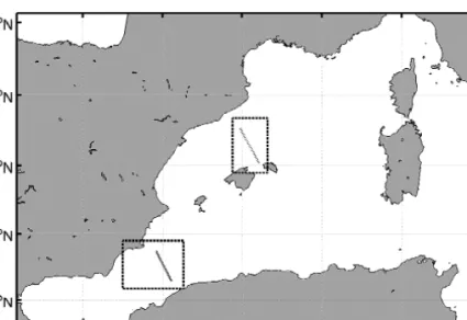
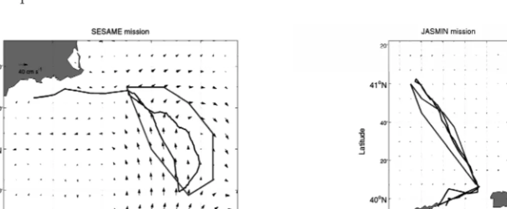
Figure 3 shows a general map of the region. Figure 4 presents two maps, one for each mission, showing the glider trajectories along with its own currents estimation during navigation. Endpoints are marked also in figure 4 as WP1 and WP2. The first segment of each mission covers the navigation between WP1 and WP2, while the second segement goes from WP2 to WP1
Figure 3.Map of WMED with the study areas marked with dashed lines and tracks marked with dotted lines.
Environmental Conditions
During the two abovementioned missions, the Thredds catalogue provided access to environmental information. Several model outputs as well as altimetry maps where available to evaluate the current field the glider was to be operating in. Figures 5 and 6 show the current fields that were considered most relevant: MFS model output and altimetry maps. The maximum agreement between the current fields and the currents estimated by the glider is achieved with altimetry.
B. GARAU, M. BONET, A. ALVAREZ, S. RUIZ ANDA. PASCUAL
Figure 4.Glider trajectories and its estimated currents.
Figure 5.SESAME and JASMIN missions and altimetry derived current field.
Figure 6.SESAME and JASMIN missions and MFS current field.
Figures 5 and 6 also show the trajectory that the glider followed when com- manded to navigate along the satellite tracks. In the case of JASMIN mission, at the right hand side of both figures, currents were weak, and the glider was able to follow the expected straight line path when moving towards the northwest and southeast.
However, during the SESAME mission, on the left hand side of both figures, a instability with strong currents was found on the glider path. This feature made the glider unable to follow the commanded route, and it was advected by the flow when performing the first segment. The second segment, where the glider moved north- west, was accomplished correctly by the glider since it was helped by the currents.
For JASMIN mission, the glider needed 5.53 days to travel the first segment (from south to north) and 4.45 days to make the second segment on its way back.
During SESAME mission, the glider spent 7.73 days performing the first segment of the mission, and just 3.09 days for the second part. Moreover, the glider was unable to reach the southest point, so the first segment was never completed as in the original mission design. The travelling time difference for the same segment per- formed in different directions provides an indication of the currents effects on the glider.
Planned Paths
Using the current fields derived from altimetry and the MFS model output, mini- mum travelling time routes have been computed. Figures 7 and 8 show the results of the path planner.
Using ADT for JASMIN mission, the path planner provided a near-straight path. Thus, the improvement with respect to the straight line was almost zero. How- ever, the estimated time to perform each segment was around 3.6 days. This fact is due to the difference between the ADT derived currents and the real currents felt by
B. GARAU, M. BONET, A. ALVAREZ, S. RUIZ ANDA. PASCUAL
Figure 7.SESAME and JASMIN planned paths on altimetry derived current field.
the glider. Altimetry was providing currents in the correct direction but magnitude was lower.
When MFS model output was used for JASMIN mission, the path planner pro- vided a slightly different pattern, but also close to the straight line. In this case, the path planner showed a higher improvement (close to 10%) than with ADT. The time estimation in this case was around 4.5 and 3.3 days for each segment, respec- tively. The explanation of the difference between results from each source is the fact that MFS was providing currents with higher intensity, but the circulation pattern was different. Therefore, the current intensities and their spatial distribution played an important role in both the shape of the path and the time estimation provided by the path planner.
Using ADT for SESAME mission, the path planner provided a very different path for both segments. While the first segment should be performed describing a curve, the second segment was to be performed in almost straight line path. The improvement with respect to the straight line was very high in the first segment (around 57%). For the second segment, as it was already straight, no improvement was made by the path planner.
When MFS model output was used for SESAME mission, the path planner provided a very different pattern. In this case, results were dismissed because of the big misfit between glider estimated currents and current field. The model output was reproducing the eddy on the west of its position. Thus, the path planner results were computed over a wrong current field.
Given these two examples of deployments, it is reasonable to say that the path planner could not improve the glider performance in JASMIN mission, but could have improved travelling time significantly during SESAME mission, where the
Figure 8. SESAME and JASMIN planned paths on MFS current field.
currents were much stronger. This fact agrees with previous works conclusions about the path planner applicability.
DISCUSSION
In this work, extensive computations have been carried out to calculate by means of the A* based path planner, optimal paths (in terms of energy cost) in realistic ocean environments. Different sources of information have been used to capture the uncertainty of the current field used as input. The study is focussed on practical cases where the AUV develops a constant thrust independently of the current field where it is immersed. This substantially differs with previous works where the AUV was considered to adapt its speed to keep constant the total velocity with respect to the ground [9]. Now, minimum energy paths are also paths with minimum travel time being the problem more restrictive.
Concerning the benefits of path planning, results indicate that these are scarce when the vehicle velocity is clearly superior to the background current field. Sub- stantial benefits of path planning are only obtained when the vehicle and current speeds are comparable. The velocity of present AUVs developing missions in the ocean is usually superior to current speeds normally found at the ocean. Neverthe- less, path planning is required in those ocean areas characterized by strong currents.
There, current intensities can reach values equal or even superior to the AUV veloci- ty. In these cases, coupling a numerical ocean model or any other current field obser- vation with a path planning algorithm constitutes an optimum solution to ensure the success and safety of the AUV mission.
The proposed techniques provide robustness and efficiency to AUVs. Robust- ness can be seen in the feasibility analysis of the path planner results. The reachabili- ty of a location is proven if the path planner is able to find a route to that destination.
Thanks to the completeness of the searching algorithm, an impossible mission could be dismissed before deploying an AUV in a hazardous area. Efficiency plays an important role even when the straight path is feasible. Using the path planner, the scientists can replan the AUV trajectory to visit the same locations in a shorter time.
This time saving allows for longer (in distance) or energy exhaustive (more sensors) missions.
B. GARAU, M. BONET, A. ALVAREZ, S. RUIZ ANDA. PASCUAL
REFERENCES
Alvarez, A. and Caiti, A. (2001): A genetic algorithm for autonomous underwater vehicle route planning in ocean environments with complex space-time variability.Proceedings of the IFAC Control Applications of Marine Systems (CAMS 2001).
Alvarez, A. and Caiti, A. (2002): Interactions of autonomous underwater vehicles with vari- able scale ocean structures. Proceedings of the IFAC World Conference Systems.
Alvarez, A.; Caiti, A. and Onken, R. (2004): Evolutionary path planning for autonomous underwater vehicles in a variable ocean, IEEE Journal of Oceanic Engineering29, no. 2, 12. pp. 418-429.
Bouffard, J.; Roblou, L.; Birol, F.; Pascual, A.; Fenoglio-Marc, L.; Cancet, M.; Morrow, R.
and Ménard, Y. (2009): Assessment of improved coastal altimetry strategies over the NMW Sea. Costal altimetry. S. Vignudelli, A. Kostianoy, P. Cipollini and J. Benveniste Eds. Springer-Verlag. Submitted
Bryan, K. (1969): A numerical method for the study of the circulation of the world ocean.
Journal of Computational Physics, 4, 347-376.
Carroll, K. P.; McClaran, S. R.; Nelson, E. L.; Barnett, D. M.; Friesen, D. K. and Williams, G.
N. (1992): AUV path planning: An A* approach. Proceedings of the Symposium on AUV Technology (AUV92), pp. 3-8.
Cox, M.D. (1984). A primitive equation, 3-dimensional model of the ocean. GFDL Ocean Group Tech. Rep.N^. 1, 143 pp.
Creed, E.L.; Mudgal, C.; Glenn, S.M.; Schofield, O.M.; Jones, C.P. and Webb, D.C. (2002):
Using a fleet of slocum battery gliders in a regional scale coastal ocean observatory, Oceans ‘02 MTS/IEEE, Volume 1, 29-31 Oct. 2002 Page(s):320 – 324
Galea, A. M. (1999): Various methods for obtaining the optimal path for a glider vehicle in shallow water and high currents.Proceedings of the 11th International Symposium on Unmanned Untethered Submersible Technology.pp. 150-161.
Garau, B.; Alvarez, A. and Oliver, G. (2005): Path Planning of Autonomous Underwater Vehicles in Current Fields with Complex Spatial Variability: an A* Approach,Proceed- ings of the 2005 IEEE International Conference on Robotics and Automation, pp. 195-199.
Holland, W. R. and McWilliams, J. C. (1987):Computer modelling in physical oceanography from the global circulation to turbulence. Physics Today pp. 51-57.
Pacanowski, R. C.; K. Dixon, and A. Rosati (1990): Readme file for GFDL-MOM 1.0,Geo- phys. Fluid Dyn. Lab., Princeton, N. J.
Rio, M-H.; Poulain, P-M.; Pascual, A.; Mauri, E. and Larnicol, G. (2007): A mean dynamic topography of the Mediterranean Sea computed from altimetric data and in-situ meas- urements.Journal of Marine Systems, 65, pp. 484-508
Robinson, A. R.; Arango, H. G.; Warn-Varnas, A.; Leslie, W. G.; Miller, A. J.; Haley, P. L. and Lozano, C. J. (1996):Real-time regional forecasting. Modern approaches to data assimila- tion in ocean modeling, Amsterdam, NL: Elsevier, pp. 377-410.
Ruiz, S.; Pascual, A.; Garau, B.; Faugere, Y.; Alvarez, A. and Tintoré, J. (2008): Mesoscale dynamics of the Balearic front integrating glider and satellite data. Journal of Marine Sys- tems.In press.
Schmidt, H. and Bovio, E. (2000): Underwater vehicle networks for acoustic and oceano- graphic measurements in the littoral ocean.Proceedings of the 5th IFAC Conference Manoeuvring and Control of Marine Craft (MCMC2000) pp. 323-326.
Sugihara, K. and Yuh, J. (1997): GA-based motion planning for underwater robotic vehicle.
Proceedings of the 10th International Symposium on Unmanned Untethered Submersible Technology,pp. 406-415.
Vasudevan, C. and Ganesan, K. (1996):Case-based path planning for autonomous underwater vehicles. Autonomous Robots. pp. 79-89.
Warren, C. W. (1990). A technique for autonomous underwater vehicle route planning. IEEE Journal of Oceanic. Engineering.vol. 15, pp. 199-204.
B. GARAU, M. BONET, A. ALVAREZ, S. RUIZ ANDA. PASCUAL
AN AUTONOMOUS VEHICLE DEVELOPMENT FOR SUBMARINE OBSERVATION
S. Gomariz1, J. Prat2, P. Gaya3and J. Sole4
Received 22 September 2008; received in revised form 29 September 2008; accepted 25 de April 2009
ABSTRACT
This work proposes the development of a low-cost ocean observation vehicle. This vehicle, a hybrid between Autonomous Underwater Vehicles (AUV ) and Autonomous Surface Vehicles (ASV) moves on the surface of the sea and makes vertical immersions to obtain profiles of a water column according to a pre-estab- lished plan. Its design means production costs are low and efficiency is increased.
Also, the vehicle is able to make high resolution space and time measurements simultaneously. GPS navigation allows the platform to move along the surface of the water while a radio-modem provides direct communication links and telemetry.
The vehicle measures 1885 mm by 320 mm wide. It weighs 76 kg. It navigates at a speed of 1.5 m/s at 80% at full propulsion power and reaches a maximum depth of 20 m. It is a vehicle of electrical propulsion with an autonomy of 3-5 hours. This work outlines the mechanical and electronic design of the vehicle, as well as consid- erations for navigational and immersion experiments.
Key words. Autonomous Underwater Vehicle, vertical profiler, computer embedded.
INTRODUCTION
Despite major advances in ocean research by oceanographic ships and anchorages, tests on the marine environment are still insufficient. The limitations of convention-
Journal of Maritime Research, Vol. VI. No. II, pp. 23-36, 2009 Copyright © 2009. SEECMAR
Printed in Santander (Spain). All rights reserved ISSN: 1697-4840
1Titular professor.Universitat Politècnica de Catalunya ([email protected]), Avda. Victor Bala- guer s/n 08800 Vilanova i la Geltrú. Spain. 2 Titular professor. Universitat Politècnica de Catalunya ([email protected]), Avda. Victor Balaguer s/n 08800 Vilanova i la Geltrú. Spain.3 Titular professor. Univer- sitat Politècnica de Catalunya ([email protected]), Avda. Victor Balaguer s/n. 08800 Vilanova i la Geltrú.
Spain.4 Titular professor. Universitat Politècnica de Catalunya ([email protected]), Av. Victor Balaguer s/n.
08800 Vilanova i la Geltrú. Spain.
al oceanic observation platforms cannot carry out tests in the sea and provide the required space and time measurements. For this reason and with the aid of recent technological advances, the development of new oceanographic observation plat- forms which are able to carry out high-resolution space and time interdisciplinary measurements simultaneously, have been tested. Observation platforms referred to as Gliders, Autonomous Underwater Vehicles (AUVs) and Autonomous Surface Vehicles (ASVs) have already been designed (Meyrowitz et al, 1996) (Blidberg, D.R, 2001). This project proposes the development of a low-cost oceanic observation vehicle which is a hybrid between the AUVs and ASVs. The vehicle moves along the surface of the sea and makes vertical immersions to obtain vertical profiles of a water column in agreement with a pre-established plan (Dabholkar et al, 2007) (Byron et al, 2007). These two characteristics of the observation platform lower the production costs and increase its efficiency. GPS navigation will allow the platform to move along the surface of the water while a radio-modem will provide direct communica- tion links and telemetry.
MECHANICAL DESIGN OF THE VEHICLE
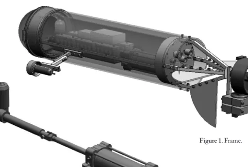
The design proposed here is a prototype which will have to be modified. The plat- form design is made up of a support structure on which the steering and propulsion mechanisms are attached. This structure is not watertight, thus allowing us to drill holes wherever required.
A watertight cylindrical module is located inside the support structure. It houses the immersion actuator and the electronics control, as well as the power supply pro- vided by the batteries (Egeskov, 1994).
Support Structure
As figure 1 shows, the support structure is made up of a PVC cylinder, 1.2m in length by 32cm in outer diameter. The simple construction means it is easy to make modifications. The final result is a platform which can house the bulky elements of the vehicle such as the batteries and the immersion actuator in the minimum space possible. The main Seaeye(™)propulsion engine is located at one the end of the sup- port structure (Seaye). This engine, without brushes, runs on a supply voltage of 24V DC and nominal current of 5A, which provides a maximum thrusting of 110N to 950rpm (Dewijs, 2000).
Individual Seabotix(™)engines are located on the sides of the cylinder. These engines have a maximum thrust of 25N at a maximum power of 80W and are pow- ered with 24V DC (Seabotix). When these engines are used, the course of the vehi- cle can be altered. This solution was favoured instead of a rudder system with a hydraulic cylinder because its construction is simple. (Desset et al, 2005). The engines, located on the sides of the device are attached to the support structure by
means of a stainless steel telescope tube that allows the spindle, located on both of the vehicle’s engines, to be altered during testing.
The main engine is attached to the support structure by means of a stainless steel tube and mechanized nylon blocks provide adequate rigidity.
Finally, depth and direction auto-stabilizers are located on the stern once again to ensure stability.
The bow is finished with a carbon fibre hemisphere.
Watertight Module
As figure 1 shows, the watertight module contains the set of immersion equipment, the electronic signal reception modules and engine control, and the power supply batteries.
All these parts are joined to the watertight PVC cylinder by means of a metallic structure. See below.
The watertight module is covered in black nylon. An o-ring and 12 M6 screws guarantee watertightness.
The design of the emersion and immersion equipment is composed of a com- mercial pneumatic stainless steel cylinder with a displacement of 1500 cm3and a lin- ear electrical actuator which can cover a maximum distance of 200mm and a thrust force of 3KN. See figure 2.
S. GOMARIZ, J. PRAT2, P. GAYA ANDJ. SOLE
Figure 1. Frame.
Figure 2.Emersion and immersion actuator.
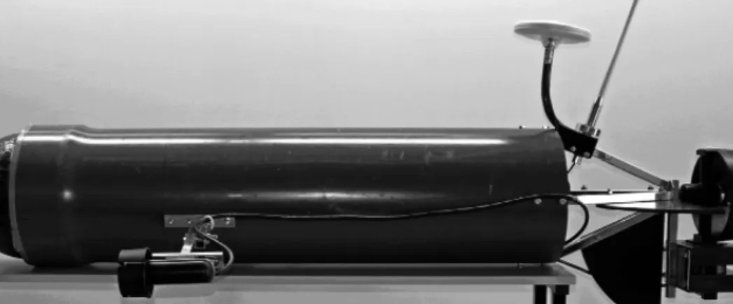
Complete structure of the vehicle.
Figure 3 and figure 4 show the external structure and watertight module of the con- structed vehicle, respectively.
It is worth highlighting, that the position of the center of gravity ensures stabili- ty in immersion/emersion operations.
The payload works out at 5kg, approximately, on a gross weight of the 76kg plat- form.
Figure 3. Constructed vehicle.
Figure 4. Constructed watertight module
ELECTRONIC DESIGN. CONTROL PHASE
The autonomous navigation control system is made up of an embedded computer and the elements necessary for communication, navigation and propulsion and data acquisition. Safety elements are also included (Desa et al, 2007). In figure 5 the dia- gram for the autonomous control of the vehicle is described.
Figure 5.Diagram of the autonomous control system
Communication between the vehicle and the station located on shore is bidirec- tional and a Farell Instruments(™)industrial modem T-MODC48 has been used.
See figure 6. Its features include a data rate of 4800 bps, protocol-transparent and a configurable carrier power of 100mW/5W that allows a maximum range of 10km and +/- 1 ppm stability level from -30ºC to 60ºC. (Farell).
A PC/104 embedded computer (PM-6100 AEWIN) makes up the central con- trol of the vehicle, see figure 7. It has an embedded AMD® Geode™ LX800 CPU up to 500MHz. This is of limited size, weight and power consumption (max 12W ). It also has a low heat loss (Aewin). It is managed by a Windows XP operating system stored in a com- pact flash memory which provides good protection from vibration.
The propulsion control system is a SSC32 Lynxmotion driver. See figure 8.
This transforms the RS232 signal from the PC/104 in a modulated PWM sig- nal that acts on the engine power driv-
S. GOMARIZ, J. PRAT2, P. GAYA ANDJ. SOLE
Figura 6.Radio módem T-MODC48.
ers.This servo-controller has 32 channels with 1uS-0.09º resolution and 1uS/Second speed.
This can work at a velocity of 2400, 9600, 38.4k, 115.2k bauds. (Lynxmotion)
Several power drivers have been devel- oped to adapt the modulated PWM signal received from the SSC32 so that the vehicle’s engines can execute the control orders.
Power steering driver. The steering orders received are transferred to individual adjustable-speed drives that control the engines responsible for moving to the left and right. These adjustable-speed drives incorpo- rate the power electronics necessary to adapt to the engines changing requirements.
Power driver of immersion/emersion. The immersion/emersion orders are applied to a control circuit that acts on the engine-cylinder equipment.
This control circuit incorporates a microcontroller PIC 16F88 that interprets the signal received and consequently executes the stop/immersion/emersion orders on the electrical engine of the immersion/emersion equipment.
The pneumatic cylinder incorporates individual magnetic limit switches which can block the electric engine’s actuators and also act as a security system limiting the total displacement of the cylinder.
Power driver for propulsion.The propulsion orders are processed on a microcontroller PIC16F873, which provides the control signal via RS485 to the propulsion engine.
This engine includes the control and power electronics necessary to decode the orders received via RS485.
The navigation system is a digital com- pass and a three-axis inclinometer, PNI TCM-2.6, see figure 9a. The TCM 2.6 is a 3-axis tilt-compensated compass- heading (also known as azimuth, yaw, or bearing angle) module with electron- ic gimballing to provide accurate head- ing, pitch, and roll measurements over a
±80° tilt range. This high-precision (heading accuracy 0.8°), high-resolution (Compass heading 0.1°) navigation sys- tem runs on low power (< 20 mA typi- cal draw) (PNI).
Figure 7.PC/104+ PM-6100
Figure 8.Controlled SSC32.
The navigation system also has a global positioning system GPS, Magellan DG14™, which provides the precise location of the vehicle during a mission, see figure 9b.
The DG14™is a sub-meter GPS+Beacon+SBAS receiver. It incorporates sig- nals from Satellite Based Augmentation Systems (SBAS), such as WAAS, EGNOS
& MSAS, or an embedded beacon receiver, to provide sub-meters differential posi- tioning. DG14 can emit SBAS ranging, ephemeris and differential corrections through the serial port. Although DG14 offers three standard RS232 ports, it is also capable of single port operation.
It can provide up to 20-Hz precise three-dimensional positions and raw data for real-time guidance and navigation (Magellan).
Figure 9. Navigation System. (a) PNI TCM-2.6 (b) DGPS, DG14
All this equipment is assembled inside two PVC boxes, as seen in Figure 10.
One box houses the PC/104 with the navigation system and the other is equipped with the propulsion system. For both boxes a power bus which uses 24V, 12V and 5V has been installed. These voltages are generated from 6 Ni-Cd batteries, 24V nominal voltage and 21AH capacity, through a power stage implemented using
S. GOMARIZ, J. PRAT2, P. GAYA ANDJ. SOLE
Figure 10. Inside layout of the watertight module
switched dc-dc converters, located in a separate box.
Safety elements for the vehicle and a data acquisition system will be developed in the second stage of the project. Figure 10 shows the layout of all the elements in the watertight module.
SOFTWARE DESIGN. TRACKING STATION
The vehicle needs user interaction in terms of control parameters, operational verifi- cation and data acquisition and downloading. A program has been designed which reads/writes the data received/sent by radio-modem, checks for transmission errors and represents the information graphically. Figure 11 shows the graphical user inter- face (GUI). The GUI has a two-page front-end. The main page incorporates direc- tion, roll and pitch angles indicators and also an artificial horizon to view the data transmitted by the compass / inclinometer. This page also includes a series of Scroll- bars and buttons to control the vehicle’s engine. The second page presents the user with each of the parameters that the GPS receiver provides using TextBox and a variety of geo-maps to locate the position of the vehicle.
EXPERIMENTAL TESTS
When the vehicle was initially placed in the water, balance had to be adjusted. It was obtained by incorporating a 3.6kg ballast in the prow and a 1.5kg push in the stern.
This was sufficient to allow the navigation and immersion tests to begin. In the nav- igation test the speed was approximately 1.5m/s with the control of the propulsion engine at 80% at full power. By using the lateral engines at full power and decreasing the propulsion of the first engine the trajectory, variation is obtained very easily. The immersion tests were carried out with complete normality acting on the engine- cylinder equipment.
CONCLUSIONS
The result so far is a robust platform which is relatively small and light, factors which facilitate its manageability and operability. To sum up we can say that a low- cost oceanic observation platform has been developed which is able to navigate on the surface of the sea and make vertical immersions to obtain water column profiles.
ACKNOWLEDGMENT
This work has been funded by the Spanish Ministry of Education and Science and the European Union (FEDER), project nº: CTM2006-12072/MAR.
S. GOMARIZ, J. PRAT2, P. GAYA ANDJ. SOLE
Figure 11.Tracking Station (a) GUI Main Page (b) Geo-Map.
REFERENCES
Aewin http://www.aewin.com.tw/main/product_info.aspx?fid=2&sid=3&sname=Embed- ded+Board&pname=PM-6100&tname=PC%2F104+CPU+Module&fname=&pid=27 Byron, J. and Tyce, R. (2007) Designing a Vertical / Horizontal AUV for Deep Ocean Sam-
pling.Proceedings of MTS/IEEE Conference and Exhibition Oceans2007. Sept. 29 2007- Oct. 4. Vancouver, Canada pp. 1 - 10
Blidberg, D. R. (2001) The development of Autonomous Underwater Vehicles (AUV); A brief summary.Autonomous Undersea Systems Institute publications (AUSI), ICRA, May, Seoul, Korea,.
Dabholkar, N., Desa, E., Afzulpurkar, S., Madhan, R., Mascarenhas, A.A.M.Q., Navelkar, G., Maurya, P.K., Prabhudesai, S., Nagvekar, S., Martins, H., Sawkar, G., Fernandes, P. and Manoj, K.K. (2007) Development of an autonomous vertical profiler for oceanographic studies,Proceedings of the International Symposium on Ocean Electronics (SYMPOL-2007), 11-14 December, Cochin, India, pp. 250-256.
Desa, E., Maurya, P.K.,Pereira, A., Pascoal, A.M., Prabhudesai, R.G., Mascarenhas, A., Mad- han, R., Matondkar, S.G.P., Navelkar, G., Prabhudesai, S. and Afzulpurkar, S. (2007) Small Autonomous Surface Vehicle for Ocean Color Remote Sensing.IEEE Journal of Oceanic Engineering,April, pp. 353 – 364 Vol. 32, Issue 2.
Desset, S., Damus, R., Hover, F., Morash, J. and Polidoro, V. (2005) Closer to deep underwa- ter science with ODYSSEY IV class hovering autonomous underwater vehicle (HAUV).Proceedings of MTS/IEEE Conference and Exhibition Oceans 2005 – Europe, 20- 23 June, Brest, France, pp. 758-762 Vol.2
DeWijs, B. (2000) AUV/ROV propulsion thrusters.Proceedings of MTS/IEEE Conference and Exhibition OCEANS 2000.11-14 September, Providence, Rhode Island, U.S.A, pp 173 - 176 vol.1
Egeskov, P., Bjerrum, A., Pascoal, A. Silvestre, C., Aage, C. and Wagner Smith, L. (1994) Design, construction and hidrodinamic testing of the AUV MARIUS.Proceedings of the AUV 94, Cambridge, Massachusetts, USA.
Farell, http://www.farell-i.com/farell/eng/productos.php
Lynxmotion, http://www.lynxmotion.com/Product.aspx?productID=395&CategoryID=52 Magellan, http://pro.magellangps.com/en/products/product.asp?PRODID=174
Meyrowitz, A.L.; Blidberg, D.R. and Michelson, R.C. (1996) Autonomous vehicles Proceedings of the IEEE.Volume 84, Issue 8, pp 1147 – 1164
PNI, http://www.pnicorp.com/products/all/tcm-2-6 Seabotix, http://seabotix.com
Seaeye, http://seaeye.com/thrusters.html
DESARROLLO DE UN VEHÍCULO AUTÓNOMO PARA OBSERVACIÓN SUBMARINA
RESUMEN
En este proyecto se desarrolla un vehículo de observación oceánica de bajo coste, híbrido entre losAutonomous Underwater Vehicles (AUV) y los Autonomous Sur- face Vehicles (ASV), esto es, que se traslada por la superficie del mar y realiza inmersiones verticales para la obtención de perfiles de la columna de agua de acuerdo con un plan previamente establecido. Estas dos características de la pla- taforma de observación propuesta, abaratan los costes de producción e incre- mentarían su eficiencia. El desplazamiento superficial de la plataforma permite la navegación mediante GPS y la comunicación directa y telemetría mediante radiomódem. Las dimensiones del vehículo son 1.885 mm de longitud y 320 de diámetro exterior, y posee un peso de 76 kg. En las pruebas de navegación alcan- zó una velocidad de 1.5 m/s a un 80% de potencia de propulsión y una profundi- dad máxima de 20 m. El vehículo posee una propulsión eléctrica con una auto- nomía de 3-5 horas.
DISEÑO MECÁNICO DEL VEHÍCULO
Teniendo en cuenta que el diseño actual corresponde a un primer prototipo sobre el que, necesariamente, deberán realizarse sucesivas modificaciones, se propone un diseño mecánico constituido por una estructura de soporte sobre la que se acoplarán los motores de dirección y propulsión. Esta estructura no es estanca, lo cual va a per- mitir realizar cualquier tipo de mecanizado. En el interior de la estructura de soporte se acopla un módulo cilíndrico estanco que contiene el actuador de inmersión y la electrónica de control, así como las baterías de alimentación.
Tal como muestra la figura 1, la estructura de soporte se compone de un cilindro de PVC de 1.2 m de longitud y 32 cm de diámetro exterior. En uno de los extremos de la estructura de soporte se acopla un motor principal de propulsión de la empresa Seaeye. Este es un motor sin escobillas con tensión de alimentación de 24V DC y corriente nominal de 5A. Proporciona un empuje máximo de 110N a 950 rpm. En los laterales del cilindro se acoplan sendos motores de la empresa Seabotix con un empuje máximo de 25N a una potencia máxima de 80 W alimentados también a 24V DC. Dichos motores permiten modificar la dirección de navegación.
Tal como muestra la figura 1, el módulo estanco contiene el grupo de inmersión y emersión, que se ha diseñado a partir de un cilindro neumático comercial de acero inoxidable con desplazamiento de 1.500 cm3y un actuador eléctrico lineal con una carrera de 200 mm y un empuje de 3KN de fuerza, alimentado a 24V. Ver figura 2.
En las figuras 3 y 4 se puede observar el vehículo construido.