X-AIRCONTROL
Zone control systems
A00000063012, 2, GB/en
© TROX GmbH 2017 Heinrich-Trox-Platz
47504 Neukirchen-Vluyn, Germany Germany
Telephone: +49 2845 202-0 Fax: +49 2845 202-265 Email: E-mail: [email protected] Internet: www.trox.de
11/2021
About this manual
This manual enables operating or service personnel to use the X-AIRCONTROL zone control system safely and efficiently.
The manual must be kept near the zone control system to be available for use at all times.
This manual is intended for use by qualified electricians and network administrators.
It is essential that these individuals ( Ä 1.4 ‘Personnel requirements’ on page 7 ) read and fully understand this manual before starting any work. The basic prereq- uisite for safe working is to comply with the safety notes and all instructions in this manual.
The local regulations for health and safety at work and the general safety regulations for the area of application of the zone control system also apply.
Illustrations in this manual are mainly for information and may differ from the actual design.
Other applicable documentation
In addition to these instructions, the following docu- ments apply:
Order confirmation
Product drawings
Data sheets for components from other suppliers, if any
Additional drawings, if any
X-AIRCONTROL operating manual
X-AIRCONTROL installation manual
X-CUBE operating manual
X-CUBE installation manual
X-CUBE compact operating manual
X-CUBE compact installation manual
Installation and commissioning manual for X-AIR- CONTROL accessories
Volume flow controller installation manual
Volume flow controller operating manual
TROX Technical Service
To ensure that your request is processed as quickly as possible, please keep the following information ready:
Product name
TROX order number
Delivery date
Brief description of the fault
Copyright
This document, including all illustrations, is protected by copyright and pertains only to the corresponding product.
Any use without our consent may be an infringement of copyright, and the violator will be held liable for any damage.
This applies in particular to:
Publishing content
Copying content
Translating content
Microcopying content
Saving content to electronic systems and editing it
Limitation of liability
The information in this manual has been compiled with reference to the applicable standards and guidelines, the state of the art, and our expertise and experience of many years.
The manufacturer does not accept any liability for dam- ages resulting from:
Non-compliance with this manual
Incorrect use
Operation or handling by untrained individuals
Unauthorised modifications
Technical changes
Use of non-approved replacement parts
The actual scope of delivery may differ from the infor- mation in this manual for bespoke constructions, addi- tional order options or as a result of recent technical changes.
The obligations agreed in the order, the general terms and conditions, the manufacturer's terms of delivery, and the legal regulations in effect at the time the con- tract is signed shall apply.
We reserve the right to make technical changes.
Warranty claims
The provisions of the respective general delivery terms apply to warranty claims. For purchase orders placed with TROX GmbH, these are the regulations in section
"Vl. Warranty claims" of the Delivery Terms of TROX GmbH, see www.trox.de/en/ .
1 Safety ... 6
1.1 Symbols used in this manual ... 6
1.2 Correct use ... 6
1.3 System owner's responsibility ... 7
1.4 Personnel requirements ... 7
1.5 Work area hazards ... 8
1.5.1 Electric shock hazard ... 8
1.5.2 Risks from rotating parts ... 8
1.5.3 Risks from hot surfaces ... 8
1.5.4 Health risk due to hygiene issues ... 8
1.5.5 Incorrect troubleshooting ... 8
1.6 Personal protective equipment ... 8
2 X-AIRCONTROL system description ... 10
2.1 System variants ... 10
2.1.1 Single room control (stand-alone) ... 10
2.1.2 Control of up to 25 rooms ... 12
2.1.3 Control with 5 zone masters ... 13
2.1.4 Control of up to 4 rooms with an X- CUBE compact ... 14
2.2 System components ... 15
2.2.1 Zone master ... 15
2.2.2 Zone modules ... 19
2.2.3 Room control panel X-AIR-CP-2T ... 31
2.2.4 Room control panel X-AIR-CP-TS ... 33
2.2.5 Sensors ... 34
3 Setting up system components on the web- server ... 45
3.1 Configuring the network access ... 45
3.2 Start screen functions ... 46
3.3 Selecting a language ... 47
3.4 Logging in to the webserver ... 48
3.5 Setting date and time on the webserver .. 49
3.6 Displaying the service screen ... 49
3.7 Zone overview ... 50
3.8 Configuring zone modules ... 51
3.8.1 Activating the device detection mode ... 51
3.8.2 Configuring actuators and sensors ... 53
3.8.3 Setting the volume flow rate ... 54
3.8.4 Checking the volume flow rate ... 54
3.8.5 Setting up a supply branch ... 55
3.8.6 Setting up an extract branch ... 56
3.8.7 Zone grouping ... 57
3.8.8 Hotel mode ... 58
3.8.9 Setting zone values ... 58
3.8.10 Configuring the zone master ... 65
3.8.11 Summer and winter compensation ... 71
3.8.12 Network connection settings ... 71
3.8.13 Firmware update ... 72
3.8.14 Displaying a zone overview ... 73
4 Configuring system components on the control panel ... 74
4.1 Switching the control panel on ... 74
4.2 Start screen functions ... 74
4.3 Setting up the X-AIR-CP-2T control panel ... 76
4.3.1 Password entry ... 76
4.3.2 Selecting a language ... 76
4.3.3 Setting the date ... 76
4.3.4 Setting the time ... 77
4.3.5 Showing or hiding the main menu ... 77
4.4 Configuring a zone module ... 78
4.4.1 Setting the configuration mode ... 78
4.4.2 Activating a frost or window contact ... 78
4.4.3 Setting an override timeout ... 79
4.4.4 Setting up schedules ... 79
4.4.5 Setting room data ... 82
4.4.6 Setting the volume flow rate for a room ... 82
4.4.7 Setting the screen saver activation time ... 83
4.4.8 Setting PI values ... 83
4.5 Using the zone module ... 84
4.5.1 Setting the volume flow rate ... 84
4.5.2 Setting a temperature setpoint value .... 85
4.6 Viewing system settings ... 85
4.6.1 Viewing room air temperatures ... 85
4.6.2 Viewing the volume flow rate for a room ... 86
4.6.3 Viewing system information ... 86
4.6.4 Help ... 86
4.6.5 Displaying alarms ... 87
5 Commissioning X-AIRCONTROL ... 88
5.1 Commissioning a stand-alone zone module ... 88
5.2 Commissioning a zone module on a zone master ... 88
6 Integrating X-AIRCONTROL with a central BMS ... 90
7 Connecting X-AIRCONTROL to an air han- dling unit (AHU) ... 91
8 Setting up MP bus or Modbus actuators ... 92
8.1 Addressing MP bus or Modbus actuators ... 92
8.2 LEDs on MP bus or Modbus actuators .... 92
8.3 Configuring MP bus or Modbus actuators ... 92
9 Troubleshooting ... 96
9.1 Safe troubleshooting ... 96
9.2 Alarms displayed on the control panel .... 96
10 Wiring documents ... 104
10.1 Zone master ... 104
10.2 Zone module X-AIR-ZMO-MP ... 105
10.3 Zone module X-AIR-ZMO-MOD ... 106
10.4 Zone module X-AIR-ZMO-ANA ... 107
11 Index... 108
1 Safety
1.1 Symbols used in this manual
Safety notes
Symbols are used in this manual to alert readers to areas of potential hazard. Signal words express the degree of the hazard.
Comply with all safety instructions and proceed carefully to avoid accidents, injuries and damage to property.
DANGER!
Imminently hazardous situation which, if not avoided, will result in death or serious injury.
WARNING!
Potentially hazardous situation which, if not avoided, may result in death or serious injury.
CAUTION!
Potentially hazardous situation which, if not avoided, may result in minor or moderate injury.
NOTICE!
Potentially hazardous situation which, if not avoided, may result in property damage.
ENVIRONMENT!
Environmental pollution hazard.
Tips and recommendations
Useful tips and recommendations as well as informa- tion for efficient and fault-free operation.
Specific safety notes
The following symbols are used in safety notes to alert you to specific hazards:
Warning signs Type of danger
Warning – danger zone.
Additional markers
In order to highlight instructions, results, lists, refer- ences and other elements, the following markers are used in this manual:
Marker Explanation
1., 2., 3. ...
Step-by-step instructions
ð Results of actions
References to sections in this manual and to other applicable documents
Lists without a defined sequence [Switch] Operating elements (e.g. push but-
tons, switches), display elements (e.g. LEDs)
‘Display’ Screen elements (e.g. buttons or menus)
1.2 Correct use
The X-AIRCONTROL zone control system consists of a zone master and several zone modules plus sensors; it is designed exclusively for the configuration, adjustment and monitoring of ventilation and air conditioning sys- tems in buildings and in individual rooms.
Incorrect use
WARNING!
Danger due to incorrect use!
Incorrect use of X-AIRCONTROL can lead to dan- gerous situations.
– Do not use the system as a replacement for required regular inspections, i.e. do not skip inspections that are stipulated in building regula- tions.
– Do not use the system for fire protection or smoke extract purposes.
– Do not use the system in rooms with explosive gases.
– Do not use the system in wet areas.
– Do not use the system with sensors or accesso- ries provided by others.
– Do not use the signals of the volt-free outputs for safety functions.
Correct use
1.3 System owner's responsibility
System owner
The system owner is a natural or legal person who for commercial or business purposes owns or manages X- AIRCONTROL or allows third parties to use or operate it, but continues to bear legal responsibility for the safety of users, staff or third parties while the product is in use.
System owner's obligations
The system is intended for commercial use. The system owner is therefore subject to the legal obligations of occupational health and safety regulations.
In addition to the safety notes in this manual, the appli- cable regulations for safety, accident prevention and environmental protection must also be complied with.
In particular:
The system owner must be aware of the applicable occupational health and safety regulations and carry out a risk assessment to determine any additional hazards that may exist or result from the specific working conditions at the installation location of X- AIRCONTROL. The system owner has to create operating instructions for X-AIRCONTROL that reflect the results of this risk assessment.
The system owner has to ensure, throughout the entire operating period of X-AIRCONTROL, that these operating instructions conform to applicable standards and guidelines; in case of any deviation, the system owner has to adapt the instructions.
The system owner must name responsible persons for commissioning and service of the system.
The system owner has to ensure that all individuals who handle or use X-AIRCONTROL have read and understood this manual.
The system owner must regularly provide training for the personnel and inform them of any dangers.
The system owner must provide the employees with the required personal protective equipment.
The system owner must have all safeguards tested regularly to ensure that they are functional and com- plete.
The system owner must observe the local fire regu- lations.
1.4 Personnel requirements
Qualification
WARNING!
Danger of injury or risk of damage to property due to insufficiently qualified individuals!
Insufficiently qualified individuals are not aware of the risks involved in working with this system and its components and are hence likely to put themselves or others into danger, causing severe or fatal injuries.
– Have any work carried out only by qualified per- sonnel.
– Keep insufficiently qualified individuals away from the work area.
The work described in this manual has to be carried out by individuals with the qualification, training, knowledge and experience described below:
HVAC technician
HVAC technicians are individuals who have sufficient professional or technical training in the field they are working in to enable them to carry out their assigned duties at the level of responsibility allocated to them and in compliance with the relevant guidelines, safety regu- lations and instructions. HVAC technicians are individ- uals who have in-depth knowledge and skills related to HVAC systems; they are also responsible for the profes- sional completion of the work under consideration.
HVAC technicians are individuals who have sufficient professional or technical training, knowledge and actual experience to enable them to work on HVAC systems, understand any potential hazards related to the work under consideration, and recognise and avoid any risks involved.
Network administrator
Network administrators design, install, configure and maintain the IT infrastructure in companies or organisa- tions.
Skilled qualified electrician
Skilled qualified electricians are individuals who have sufficient professional or technical training, knowledge and actual experience to enable them to work on elec- trical systems, understand any potential hazards related to the work under consideration, and recognise and avoid any risks involved.
Personnel requirements
Passwords
Some software functions are password protected to pre- vent unauthorised individuals from entering or changing data ( Ä 3.4 ‘Logging in to the webserver’
on page 48 , Ä 4.3.1 ‘Password entry’
on page 76 ).
1.5 Work area hazards 1.5.1 Electric shock hazard
Electric current
DANGER!
Danger of death due to electric current!
Danger of electric shock! Do not touch any live com- ponents! Damaged insulation or damaged parts are a life threatening hazard.
– Only skilled qualified electricians must work on the electrical systems.
– If the insulation is damaged, disconnect the power supply immediately and have the insula- tion repaired.
– Before you start any service jobs, ensure that no voltage is present.
– Ensure that live parts do not come into contact with moisture. Moisture can cause a short circuit.
1.5.2 Risks from rotating parts
Rotating parts
WARNING!
Risk of injury from rotating parts!
Rotating parts in the fan can cause serious injuries.
– Before you start any service jobs, interrupt the power supply.
– Do not reach into the moving fan.
– The fan does not stop immediately! Check that no parts are moving once you have opened the casing cover.
– Do not open the casing cover while the fan is in operation.
1.5.3 Risks from hot surfaces
Hot surfaces
WARNING!
Risk of burns from hot surfaces!
Skin contact with hot surfaces causes severe skin burns.
– Before you start any service jobs on the electric duct heater, interrupt the power supply.
– Wait for 10 minutes after you have pulled the mains plug.
– Before you start working, make sure that all sur- faces have cooled down to ambient temperature.
1.5.4 Health risk due to hygiene issues
Hygiene issues
CAUTION!
Health risk due to hygiene issues!
When the unit is not used for several weeks, bac- teriae and germs may start growing in the air filter and in the recuperative heat exchanger.
– Change the air filters and clean the recuperative heat exchanger after lengthy idle periods.
– Change filters and clean the recuperative heat exchanger in the recommended intervals.
1.5.5 Incorrect troubleshooting
WARNING!
Risk of injury from incorrect troubleshooting!
Incorrect troubleshooting can cause serious injuries and considerable damage to property.
– In case of any error or fault on the ventilation unit, first pull the mains plug.
– Faults that cannot be rectified according to the instructions in the ‘Troubleshooting’ section have to be rectified by the TROX Technical Service.
– Do not open the casing cover while the ventila- tion unit is in operation.
1.6 Personal protective equipment
WARNING!
Health risk due to inadequate personal protective equipment!
– Ensure that personnel uses the correct personal protective equipment for the location where the Personal protective equipment
Personal protective equipment is equipment that pro- tects the user against health or safety risks at work.
The personal protective equipment (type etc.) required for a job depends on the installation location and the ambient conditions.
The system owner has to provide the correct personal protective equipment for each commissioning and service job.
If the system owner does not provide any personal pro- tective equipment, at least the following equipment has to be used:
Industrial safety helmet
Industrial safety helmets protect the head from falling objects, suspended loads, and the effects of striking the head against stationary objects.
Protective clothing
Protective clothing is close-fitting, with low tear resist- ance, close-fitting sleeves, and no projecting parts. It prevents entanglement in moving machinery.
Safety shoes
Safety shoes protect the feet against crushing, falling parts, and from slipping on slippery ground.
Safety goggles
Protective gloves
Protective gloves protect hands from friction, abrasions, punctures and deep cuts.
Personal protective equipment
2 X-AIRCONTROL system description
2.1 System variants
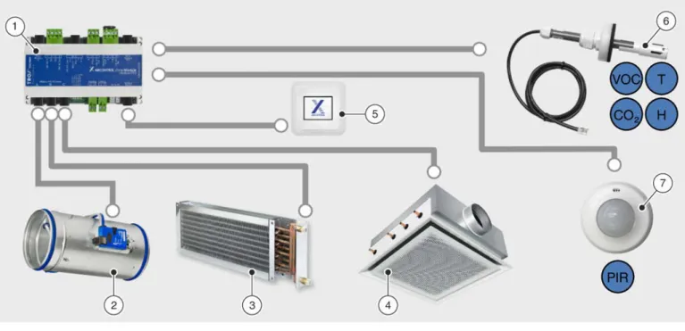
2.1.1 Single room control (stand-alone)
Fig. 1: Single room control 1 Zone module
2 Supply air / extract air control 3 Heating
4 Cooling
5 Room control panel
6 Sensors for temperature, humidity, CO2/VOC 7 Motion detector (PIR sensor)
Single room control is the smallest unit for X-AIRCONTROL. With this setup, one zone module controls one zone (e.g. a room). Zone modules come in three variants. Make sure that each VAV terminal unit and controller fit the bus system used for the zone module.
Zone modules
X-AIR-ZMO-ANA
( Ä 2.2.2.3 ‘Zone module X-AIR-ZMO-ANA’ on page 28 )
X-AIR-ZMO-MP
( Ä 2.2.2.1 ‘Zone module X-AIR-ZMO-MP’ on page 22 )
X-AIR-ZMO-MOD
( Ä 2.2.2.2 ‘Zone module X-AIR-ZMO-MOD’ on page 25 ) Requirements
Installation on a standard 35 mm mounting rail (to DIN standard)
Casing suitable for the classification of the installation location ( Ä 2.2.2.4 ‘Zone module X-AIR-ZMO-COVER’ on page 31 )
24 V AC supply voltage (by others)
No more than 3 zone modules connected to 1 power supply
Control panel X-AIR-CP-2T (2" touch panel)
( Ä 2.2.3 ‘Room control panel X-AIR-CP-2T’ on page 31 ) System variants > Single room control (stand-alone)
Application
Temperature control (heating/cooling)
– Room temperature control / extract air temperature control
Volume flow rate control (temperature, humidity, CO2/VOC) – Room temperature control / extract air temperature control – Room humidity control / Extract air humidity control – Room/extract air/CO2 control or VOC control
Timer programmes
– Week timer with up to 4 switching times per day – Real time clock
Additional functions
– Window contact/dew point sensor or frost protection sensor – Motion detector (PIR sensor)
Operating modes
Automatic mode
Zones are automatically controlled based on measured values and based on demand.
Minimum volume flow rate
The set minimum volume flow rates are maintained. Temperature control by means of water-side valves is not affected.
Maximum volume flow rate
The set maximum volume flow rates are maintained. Temperature control by means of water-side valves is not affected.
System variants > Single room control (stand-alone)
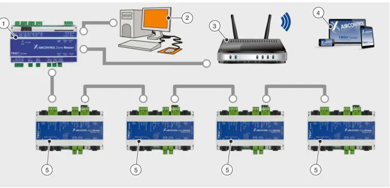
2.1.2 Control of up to 25 rooms
Fig. 2: Control of up to 25 rooms 1 Zone master
2 Central BMS 3 Network access
4 X-AIRCONTROL software/webserver 5 Zone modules
You can connect up to 25 zone modules to a zone master ( Fig. 2 /1) and hence control them centrally. For system commissioning and configuration you can use the webserver that is included in the zone master.
Requirements
Works only with X-AIR-ZMAS zone master
Configuration and commissioning with webserver using a personal computer or notebook
Control of several zones using the zone master as a higher-level interface for data exchange, configuration and display
Up to 25 zone modules connected to one zone master (section)
Zone bus as daisy chain Application
Same as stand-alone version, Ä 10 Additional application functions
Override control for maximum or minimum volume flow rate
Duct pressure monitoring
Summer and winter compensation
Hotel mode
Zone grouping
Fire mode Operating modes
Automatic mode
Zones are automatically controlled based on measured values and based on demand.
Minimum volume flow rate
The set minimum volume flow rates are maintained. Temperature control by means of water-side valves is not affected.
Maximum volume flow rate
The set maximum volume flow rates are maintained. Temperature control by means of water-side valves is not System variants > Control of up to 25 rooms
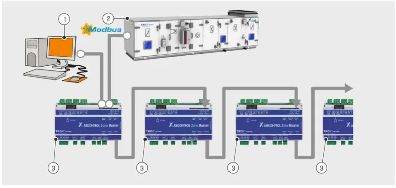
2.1.3 Control with 5 zone masters
Fig. 3: Control with 5 zone masters 1 Central BMS
2 Air handling unit (Modbus RTU) 3 X-AIRCONTROL zone master Requirement
No more than 5 zone masters, cascading
You can connect up to five X-AIRCONTROL zone masters to form a system. You then have to connect the zone masters in a cascade between the 'Zone Master In' input and the 'Zone Master Out' output. You need to connect each X-AIRCONTROL zone master to the same LAN (subnetwork) so that the web server acts as the common inter- face.
Each of the five X-AIRCONTROL zone masters requires a separate IP address.
Example:
X-AIRCONTROL zone master IP address
Section 1 192.168.0.201 (factory setting)
Section 2 192.168.0.202
Section 3 192.168.0.203
Section 4 192.168.0.204
Section 5 192.168.0.205
System variants > Control with 5 zone masters
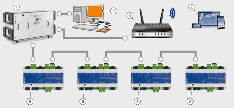
2.1.4 Control of up to 4 rooms with an X-CUBE compact
Fig. 4: Control of up to 4 rooms with an X-CUBE compact 1 X-CUBE compact air handling unit
2 Central BMS 3 Network access
4 X-AIRCONTROL software 5 Zone modules
You can use an X-CUBE compact air handling unit to control an X-AIRCONTROL system for up to 4 zones (rooms).
In such a case, X-CUBE control (AHU control system) provides the control input signals for fans, volume flow con- trollers and peripheral components. You can interconnect up to 4 zone modules and control them individually. The X- AIRCONTROL software allows you to configure X-CUBE compact and each zone module using the X-CUBE control Ethernet interface. X-CUBE control is an integral part of the X-CUBE compact air handling unit.
The X-AIRCONTROL zone master function is included in X-CUBE control
Up to 4 zone modules of any type can be connected
Configuration is done using the integral webserver
Remote maintenance is possible (central BMS)
System variants > Control of up to 4 rooms with an X-CUBE compact
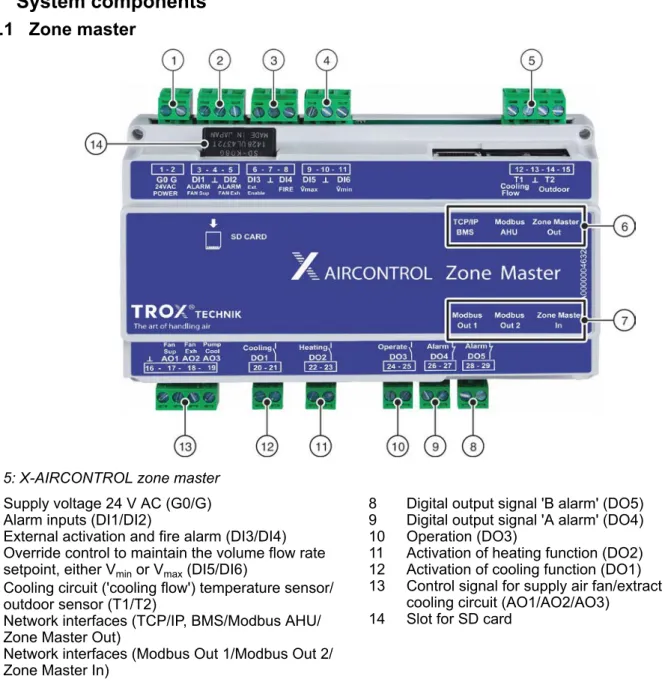
2.2 System components 2.2.1 Zone master
Fig. 5: X-AIRCONTROL zone master 1 Supply voltage 24 V AC (G0/G) 2 Alarm inputs (DI1/DI2)
3 External activation and fire alarm (DI3/DI4) 4 Override control to maintain the volume flow rate
setpoint, either Vmin or Vmax (DI5/DI6)
5 Cooling circuit ('cooling flow') temperature sensor/
outdoor sensor (T1/T2)
6 Network interfaces (TCP/IP, BMS/Modbus AHU/
Zone Master Out)
7 Network interfaces (Modbus Out 1/Modbus Out 2/
Zone Master In)
8 Digital output signal 'B alarm' (DO5) 9 Digital output signal 'A alarm' (DO4) 10 Operation (DO3)
11 Activation of heating function (DO2) 12 Activation of cooling function (DO1)
13 Control signal for supply air fan/extract air fan/
cooling circuit (AO1/AO2/AO3) 14 Slot for SD card
Connections
Analogue output signals (0 – 10 V)
(AO1, AO2, AO3)
Terminal no.
AO1 (Fan Sup) 17 Control signal for a central supply air fan
AO2 (Fan Exh) 18 Control signal for a central extract air fan
AO3 (Pump Cool) 19 Control signal for the cooling circuit
(e.g. circulator pump)
┴ 16 GND
System components > Zone master
Digital output signals (DO1, DO2, DO3, DO4, DO5)
Terminal no.
DO1 (Cooling) 20 - 21 Activation of cooling function
DO2 (Heating) 22 - 23 Activation of heating function
DO3 (Operate) 24 - 25 Operation
DO4 (Alarm) 26 - 27 A alarm
DO5 (Alarm) 28 - 29 B alarm
Supply voltage (G0/G)
Terminal no.
G0 1
Supply voltage 24 V AC
G 2
Digital input signals (DI1, DI2, DI3, DI4, DI5, DI6)
Terminal no.
DI1 (Alarm Fan Sup) 3 Supply air fan alarm input
┴ 4 GND
DI2 (Alarm Fan Exh) 5 Extract air fan alarm input
DI3 (Ext. Enable) 6 External activation (e.g. signal from central BMS) that enables zone controllers to work in auto mode
┴ 7 GND
DI4 (FIRE) 8 Fire alarm (override control of supply and extract air
flow controllers in the event of a fire)
DI5 (V̇max) 9 Override control: volume flow controllers maintain Vmax
┴ 10 GND
DI6 (V̇min) 11 Override control: volume flow controllers maintain Vmin
Temperature sensor connec- tions
(T1, T2)
Terminal no.
T1 (Cooling flow) 12 Temperature sensor of cooling circuit
┴ 13 GND
T2 (Outdoor) 14 Outdoor sensor
– 15 Not used
System components > Zone master
SD interface Terminal no.
SD card – Slot for SD card
Communication interfaces Terminal no.
TCP/IP, BMS – Connection to a TCP/IP network (RJ45 socket)
Modbus AHU – Connection to an air handling unit (RS485 socket)
Zonemaster Out – Connection for cascading (only zone master)
Communication interfaces Terminal no.
Modbus Out 1 – 'Zone Modbus Out' for the connection of zone modules
Modbus Out 2 – 'Zone Modbus Out' for the connection of zone modules
Zonemaster In – Connection for cascading (only zone master)
Technical data
Dimensions and weight
Width 156 mm
Height 110 mm
Depth 58 mm
Weight 430 g
Electrical data
Supply voltage 24 V AC ±10%
Power consumption (master) ≤ 5 VA
(without any external sensors or actuators)
Cable diameter 1.5 mm2 max.
SD card SDHC, 8 GB max.
Network properties
System components > Zone master
Network properties
TCP/IP connections RJ45 plug (8P8C)
10/100 Mbit Ethernet
Modbus communication 5 x RJ12 plugs (6P/6C)
Modbus Out1 / Out2: RS-485; 38.4 kBd Modbus Master In / Master Out: RS-485; 38.4 kBd
Modbus AHU: RS-485; Baud rate: 4800 Bd, 9600 Bd, 19200 Bd, 38400 Bd; 8 data bits; parity: no/even/uneven; 1 or 2 stop bits; address: 1 - 240 Length of cable to modules Cable type: Telephone ribbon cable 6-core with RJ12 plugs (6P/6C)
100 m max.
Length of cable to master Cable type: Telephone ribbon cable 6-core with RJ12 plugs (6P/6C) 100 m max.
Inputs/outputs Digital inputs
[DI1|DI2|DI3|DI4|DI5|DI6]
6 × pull-up with ground contact
Digital outputs [DO1|DO2]
2 x max. 5 A/230 V
Digital outputs [DO3|DO4|DO5]
3 x 5 A/30 V max.
Sensor inputs [T1|T2]
2 x for PT1000
Analogue outputs [AO1|AO2|AO3]
3 x 0 – 10 V DC Max. load: 50 mA per output
Ambient conditions Acceptable relative humidity
(rh) 10 – 90 %
(no condensation)
Max. temperature – operation -20 to +50 °C
Max. temperature – storage -30 to +70 °C
Protection level IP 20 (EN 60529)
System components > Zone master
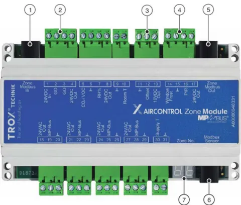
2.2.2 Zone modules
Connections found on all zone modules
Fig. 6: Zone module
1 Zone Modbus connection input
2 Supply voltage 24 V AC (In/G0/G0/Out)
3 Analogue input for setpoint value (┴/Offset/10 V DC 4 Out)Digital input for window contact/frost protection
sensor/motion detector (PIR)
5 Zone Modbus connection output 6 Modbus sensor
7 7-segment display
The connections in Fig. 6 /1 – 6 and the 7-segment display ( Fig. 6 /7) are included in all zone modules and have the same functions.
Connections
Communication interfaces Terminal no.
Modbus sensor RJ12 socket Various sensors and room control panel X-AIR-CP-2T Zone Modbus In RJ12 socket Connection to the zone master or to the preceeding
zone module
Supply voltage (G0)
Terminal no.
24 V AC In 1
System components > Zone modules
Analogue input for setpoint
values Terminal
no.
┴ 5 GND for analogue setpoint adjuster
Offset 6 Analogue input for setpoint value
10 V DC Out 7 Supply voltage for analogue setpoint adjuster, load:
10 mA max.
Digital input signals Terminal no.
Windows/Frost 8 Digital input for window contact/frost protection sensor
┴ 9 GND for window contact/frost protection contact and
for motion detector (PIR)
PIR 10 Digital input for motion detector (PIR)
24 V DC Out 11 Supply voltage for motion detector (PIR)
Load: 100 mA max.
Communication interface Terminal no.
Zone Modbus Out RJ12 socket Connection to the following zone module
Display elements
Each zone module includes a two-digit 7-segment display ( Fig. 6 /7). The 7-segment display indicates the status.
The table below shows the symbols.
Segments
Display Description
Zone module in section 1 (zone master 1) Zone module in section 2 (zone master 2) Zone module in section 3 (zone master 3) Zone module in section 4 (zone master 4) Zone module in section 5 (zone master 5) No area number has been assigned by the zone master System components > Zone modules
Zone module address
Display Description
Current zone module address as shown on the zone master (areas 1 – 25).
Current zone number (address) has not been received from the zone master
Sensor
Display Description
The temperature sensor (supply air, extract air or room air temperature) has been correctly connected
The VOC or CO2 sensor (extract air or room air) has been correctly connected The humidity sensor (extract air or room air) has been correctly connected 2 temperature sensors (supply air, extract air or room air temperature) have been
connected Sensor short circuit
Room control panel
Display Description
Room control panel X-AIR-CP-2T has been connected
Software update
Display Description
Software update in progress
Important: Do not interrupt the supply voltage!
System components > Zone modules
2.2.2.1 Zone module X-AIR-ZMO-MP
Fig. 7: Zone module X-AIR-ZMO-MP 1 MP bus output A
2 MP bus output B 3 MP bus output C 4 MP bus output D
5 Analogue input for supply air temperature sensor 6 Analogue inputs for CO2/VOC and humidity 7 Analogue input for room temperature sensor
Connections
MP bus output A Terminal
no.
24 V AC Out 18 Supply voltage for volume flow controller (6 VA max.)
MP bus 19 MP bus output A for volume flow controller
┴ 20 GND for volume flow controller
MP bus output B Terminal
no.
24 V AC Out 21 Supply voltage for volume flow controller (6 VA max.)
MP bus 22 MP bus output B for volume flow controller
┴ 23 GND for volume flow controller
System components > Zone modules
MP bus output C Terminal no.
24 V AC Out 24 Supply voltage for volume flow controller (6 VA max.)
MP bus 25 MP bus output C for volume flow controller
┴ 26 GND for volume flow controller
MP bus output D Terminal
no.
24 V AC Out 27 Supply voltage for volume flow controller (6 VA max.)
MP bus 28 MP bus output D for volume flow controller
┴ 29 GND for volume flow controller
Analogue input Terminal
no.
Supply T 30 Analogue input for supply air temperature sensor
(PT1000)
┴ 31 GND for analogue supply air temperature sensor
(PT1000)
Analogue input Terminal
no.
CO2/VOC 5 Analogue input for CO2/VOC sensor
(0 to 10 V = 0 to 2000 ppm)
┴ 6 GND for CO2/VOC and humidity sensors
rH% 7 Analogue input for humidity sensor
(0 to 10 V = 0 to 100%)
24 V DC Out 8 Supply voltage for CO2/VOC sensor (250 mA max.)
┴ 9 GND for room temperature sensor (PT1000)
Room T 10 Analogue input for room temperature sensor (PT1000)
Technical data Dimensions
Width 156 mm
System components > Zone modules
Electrical data
Supply voltage 24 V AC ± 10%
Power consumption (module) ≤ 3.5 VA
(without any external sensors or actuators)
Network properties
Modbus RTU (RS-485) outputs for actuating elements (Com- munication parameters)
3 x RJ12 plug (6P6C) Baud rate: 38.4 kBaud
1-8-N-2 (start bits, data bit, parity, stop bits)
Length of cable to modules Cable type AWG26/6C
100 m max.
Length of cable to master Cable type AWG26/6C
100 m max.
Cable length
(actuating element/sensor/room control panel)
30 m max.
MP-Bus outputs for actuating elements
(max. power rating)
4 x 6 VA max.
(in total: 24 VA max.)
Inputs/outputs
Digital inputs 2 × pull-up with ground contact
Sensor inputs 2 x for PT1000
1 x CO2 (0 – 10 V = 0 – 2000 ppm) 1 x rh% (0 – 10 V = 0 – 100%)
External temperature shift 1 x 0 – 10 V for ± 5 K max.
Cable diameter 1.5 mm2 max.
Ambient conditions Acceptable relative humidity
(rh) 10 – 90%
(no condensation)
Max. temperature – operation -20 to +50 °C
Max. temperature – storage -30 to +70 °C
Protection level IP 20 (EN 60529)
System components > Zone modules
2.2.2.2 Zone module X-AIR-ZMO-MOD
Fig. 8: Zone module X-AIR-ZMO-MOD 1 Modbus output A
2 Modbus output B 3 Modbus output C
4 Status LEDs for actuating elements
5 Digital output – heating 6 Digital output – cooling
7 Analogue inputs for CO2 and room temperature sensor (PT1000)
Connections
MP bus outputs Terminal
no.
Modbus VAV & Valves RJ12 socket
Modbus output A (max. 6 W) Modbus output B (max. 6 W) Modbus output C (max. 6 W)
Status LEDs for actuating ele-
ments Terminal
no.
VAV-Exh 1 Extract air volume flow controller – output
VAV-SUP 1 2 Supply air volume flow controller – output 1
VAV-SUP 2 3 Supply air volume flow controller – output 2
System components > Zone modules
Digital outputs Terminal no.
Heating 12
Digital output – heating 13
Cooling 14
Digital output – cooling 15
Analogue inputs (RJ12) Pin
no.
24 V DC Out 1 Supply voltage for CO2/VOC sensor (250 mA max.)
┴ 2 GND for CO2/VOC sensor
Room T 3 Analogue input for room temperature sensor 1 (PT1000)
CO2 4 Analogue input for CO2/VOC sensor
(0 to 10 V = 0 to 2000 ppm)
– 5 Not used
┴ 6 GND for room temperature sensor (PT1000)
1) If you connect an extract air sensor to the 'Modbus Sensor' input, the input for the room temperature will then be used for the supply air temperature.
Technical data
Dimensions and weight
Width 156 mm
Height 110 mm
Depth 45 mm
Weight 270 g
Electrical data
Supply voltage 24 V AC ±10%
Power consumption (module) ≤ 2 VA
(without any external sensors or actuators)
Network
Modbus communication 3 x RJ12 plug (6P/6C)
RS-485, 38.4 kBaud
Length of cable to modules Cable type: Telephone ribbon cable 6-core with RJ12 plugs (6P/6C) System components > Zone modules
Network
Length of cable to master Cable type: Telephone ribbon cable 6-core with RJ12 plugs (6P/6C) 100 m max.
Cable length
(control element/sensor/room control panel)
30 m max.
Modbus RTU outputs for actuating elements (max. power rating)
3 x 6 VA max.
(in total: 18 VA max.)
Inputs/outputs
Digital inputs 2 × pull-up with ground contact
Digital outputs 2 x max. 5 A/230 V
(Heating/Cooling)
Sensor inputs 1 x for PT1000
1 x CO2 (0 – 10 V = 0 – 2000 ppm)
External temperature shift 1 x 0 – 10 V for ± 5 K max.
Cable diameter 1.5 mm2 max.
Ambient conditions
Acceptable relative humidity (rh) 10 – 90 %
(no condensation)
Max. temperature – operation -20 to +50 °C
Max. temperature – storage -30 to +70 °C
Protection level IP 20 (EN 60529)
System components > Zone modules
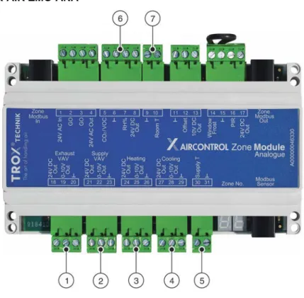
2.2.2.3 Zone module X-AIR-ZMO-ANA
Fig. 9: Zone module X-AIR-ZMO-ANA
1 Extract air volume flow controller – output 2 Supply air volume flow controller – output 3 Control element for heating – output 4 Control element for cooling – output
5 Analogue input for supply air temperature sensor 6 Analogue inputs for CO2/VOC and humidity sensors 7 Analogue input for room temperature sensor
Connections
Extract air volume flow con-
troller – output Terminal
no.
Exhaust VAV 24 V DC Out 18 Extract air volume flow controller – output (6 VA max.)
0 – 10 V Out 19 Output signal
┴ 20 GND for volume flow controller
Supply air volume flow con-
troller – output Terminal
no.
Supply VAV 24 V DC Out 21 Supply air volume flow controller – output (6 VA max.)
0 – 10 V Out 22 Output signal
┴ 23 GND for volume flow controller
System components > Zone modules
Control element for heating –
output Terminal
no.
Heating 24 V DC Out 24 Control element for heating – output (6 VA max.)
0 – 10 V Out 25 Output signal
┴ 26 GND for control element – heating
Control element for cooling –
output Terminal
no.
Cooling 24 V DC Out 27 Control element for cooling – output (6 VA max.)
0 – 10 V Out 28 Output signal
┴ 29 GND for control element – cooling
Temperature sensor Terminal
no.
Supply T 30 Analogue input for supply air temperature sensor
(PT1000)
┴ 31 GND for analogue supply air temperature sensor
(PT1000)
Analogue input Terminal
no.
CO2/VOC 5 Analogue input for CO2/VOC sensor
(0 to 10 V = 0 to 2000 ppm)
┴ 6 GND for CO2/VOC and humidity sensors
rh% 7 Analogue input for humidity sensor
(0 to 10 V = 0 to 100%)
24 V DC Out 8 Supply voltage for CO2/VOC sensor (250 mA max.)
Analogue input Terminal
no.
┴ 9 GND for room temperature sensor (PT1000)
Room T 10 Input for room temperature sensor (PT1000)
System components > Zone modules
Technical data
Dimensions and weight
Width 156 mm
Height 110 mm
Depth 45 mm
Weight 270 g
Electrical data
Supply voltage 24 V AC ±10%
Power consumption (module) ≤ 2.3 VA
(without any external sensors or actuators)
Network
Modbus communication 3 x RJ12 plug (6P/6C)
RS-485, 38.4 kBaud
Length of cable to modules Cable type: Telephone ribbon cable 6-core with RJ12 plugs (6P/6C) 100 m max.
Length of cable to master Cable type: Telephone ribbon cable 6-core with RJ12 plugs (6P/6C) 100 m max.
Cable length
(control element/sensor/room control panel)
30 m max.
Inputs/outputs
Digital inputs 2 × pull-up with ground contact
Analogue outputs (VAV)
4 x 0 – 10 V (< 50 mA)
Cable cross section 1.5 mm2 max.
Ambient conditions Acceptable relative humidity
(rh) 10 – 90 %
(no condensation)
Max. temperature – operation -20 to +50 °C
Max. temperature – storage -30 to +70 °C
Protection level IP 20 (EN 60529)
System components > Zone modules
2.2.2.4 Zone module X-AIR-ZMO-COVER
Fig. 10: X-AIRCONTROL Zone module cover
Technical data
Dimensions and weight
Width 170 mm
Length 170 mm
Height 41 mm
Casing ABS plastic, RAL 9010 (white)
Installation Can be plugged onto zone modules
2.2.3 Room control panel X-AIR-CP-2T
Fig. 11: Control panel with 2" touch display for X-AIRCONTROL
System components > Room control panel X-AIR-CP-2T
Connections
RJ12 socket Description Sensor Duct (CH) Connection
1 +24VDC
CO2/VOC CH1
+24 VDC out1
2 GND 0 – 10 V in
(0 – 10 V = 0 – 2000 ppm)
3 Bus B GND
4 Bus A
Humidity CH2
+24 VDC out 1
5 +24VDC 0-10 V in
(0 – 10 V = 0 – 100%)
6 GND GND
1) In total 200 mA max. for CH1 and CH2
Technical data Dimensions
Height 82 mm
Width 82 mm
Depth 41 mm
Installation depth 22 mm
Electrical data
Supply voltage 24 V DC ± 10%
Power consumption 775 mW
(without any external sensors) Power consumption in standby
mode 500 mW
Terminal connection
Connections Modbus: RJ12 6P6C or 4 screw terminals
Sensor: 6 screw terminals
Cable cross section 1.0 mm2 max.
Cable length 30 m max.
Ambient conditions Acceptable relative humidity
(rh) 0 – 95%
(no condensation)
Max. temperature – operation -10 to +40 °C
System components > Room control panel X-AIR-CP-2T
Ambient conditions
Max. temperature – storage -30 to +70 °C
Protection level IP 21 (EN 60529)
2.2.4 Room control panel X-AIR-CP-TS
Fig. 12: Control panel with setpoint value adjuster and room temperature sensor for X-AIRCONTROL
Connections
Terminal connections
1 + PT-1000
2 - PT-1000
3 GND
4 0 – 10 V out
5 10 V DC
Technical data
Dimensions and weight
Height 84 mm
Width 84 mm
Depth 27 mm
Electrical data
Supply voltage 10 V DC
Potentiometer (IN/OUT) 10 kohms (10 V DC)
System components > Room control panel X-AIR-CP-TS
Ambient conditions Acceptable relative humidity
(rh) 0 – 95%
(no condensation)
Max. temperature – operation -10 to +50 °C
Max. temperature – storage -20 to +60 °C
Protection level IP 30 (EN 60529)
2.2.5 Sensors
2.2.5.1 X-SENS-TEMP-RH-EXH
Fig. 13: Combined extract air temperature and humidity sensor for X-AIRCONTROL
Technical data
Dimensions and weight Length without connecting
cable 300 mm
Diameter 12 mm
Installation depth 50 – 250 mm
Weight 250 g
Electrical data
Supply voltage 24 V DC ± 25%
Power consumption 220 mW max.
Measuring range – humidity 0 – 100% rh
(no condensation)
Absolute error < 2% rh (10% – 90% rh)
< 5% rh (0% – 10% rh/90% – 100% rh) System components > Sensors
Electrical data
Measuring range – temperature -40 to 120 °C
Absolute error < 0.25 °C (15 to 40 °C)
Connection
Plug-in connecting cable RJ12 6P6C, 7000 mm long
Ambient conditions
Max. temperature – operation -20 to 50 °C (% rh 0 to +50 °C)
Max. temperature – storage -40 to 80 °C
Protection level, duct interior IP 32 (EN 60529)
Protection level, duct exterior IP 54 (EN 60529)
2.2.5.2 X-SENS-TEMP-EXH
Fig. 14: Extract air temperature sensor for X-AIRCONTROL
Technical data
Dimensions and weight Length without connecting
cable 300 mm
Diameter 12 mm
Installation depth 50 – 250 mm
Weight 250 g
System components > Sensors
Electrical data
Absolute error < 0.5 °C (-10 to 85 °C)
Measuring range – temperature -40 – 85 °C
Connection
Plug-in connecting cable RJ12 6P6C, 7000 mm long
Ambient conditions
Max. temperature – operation -20 to +50 °C (% rh 0 to +50 °C)
Max. temperature – storage -55 to +85 °C
Protection level, duct interior IP 32 (EN 60529)
Protection level, duct exterior IP 54 (EN 60529)
2.2.5.3 X-SENS-VOC
Fig. 15: VOC duct sensor for X-AIRCONTROL
Technical data
Dimensions and weight Length without connecting
cable 160 mm
Diameter 19 mm
Installation depth 65 – 105 mm
Weight 175 g
System components > Sensors
Electrical data
Supply voltage 24 V DC ± 25%
Power consumption 460 mW max.
Start-up time 15 min
Response time < 5 min
Measuring range CO2 equiva- lent
450 – 2000 ppm (no condensation)
Absolute error < 150 ppm
Airflow velocity > 0 m/s
Connection
Plug-in connecting cable RJ12 6P6C, 7000 mm long
Ambient conditions
Relative humidity 5 – 95% rh
(no condensation)
Max. temperature – operation 0 to +50 °C
Max. temperature – storage -25 to +50 °C
Protection level, duct interior IP 32 (EN 60529)
Protection level, duct exterior IP 54 (EN 60529)
2.2.5.4 X-SENS-SPLITTER
System components > Sensors
Technical data
Dimensions and weight
Width 46 mm
Length 78 mm
Height 45 mm
Weight 60 g
Connections
Spring clamp terminal 8 x 1.5 mm2
RJ12 connection 4 x RJ12 socket
Ambient conditions
Max. temperature – operation 0 to +50 °C
Max. temperature – storage -25 to +50 °C
Protection level IP 20 (EN 60529)
2.2.5.5 X-SENS-TEMP-PT1000
Fig. 17: PT1000 temperature sensor for X-AIRCONTROL
Technical data
Dimensions and weight Length without connecting
cable 126 mm
Diameter 12 mm
Installation depth 50 – 115 mm
Weight 250 g
System components > Sensors
Connection
Connecting cable, open end 4000 mm long
Measured values
Measuring range – temperature -40 °C – +85 °C
Absolute error < 0.5 °C (15 to 40 °C)
< 0.725 °C (-40 to 85 °C)
Resistance 0 °C = 1000 ohms
Measuring element PT1000
Ambient conditions
Max. temperature – operation -40 to +100 °C
Max. temperature – storage -40 to +100 °C
Protection level IP 32 (EN 60529)
2.2.5.6 X-SENS-CO2-RH
Fig. 18: Room CO2 and humidity sensor for X-AIRCONTROL
Technical data Electrical data Supply voltage
(from the X-AIRCONTROL zone module)
24 V AC/DC
Power consumption 2 W max. for 20 ms (every 3 seconds) / 1 W max. for the remaining time
CO2 output, analogue 0 – 10 V
CO2 output, switch contact 24 V DC/50 mA
CO2 sensor Optical NDIR CO2 sensor
System components > Sensors
Dimensions and weight
Width 105 mm
Height 80 mm
Depth 23.5 mm
Casing ABS plastic, RAL 9010 (white)
Measured values
CO2 measuring range 0 – 2000 ppm
Humidity measuring range 0 – 100 %
Resolution 1 ppm
Accuracy ±30 ppm
20 – 80% rh ±3%
Ambient conditions
Max. temperature – operation 0 to +50 °C
Protection level IP 30
2.2.5.7 X-SENS-DEWP
Fig. 19: Dew point sensor for X-AIRCONTROL
Technical data Electrical data Supply voltage
(from the X-AIRCONTROL zone module)
24 V AC/DC ±20%
Power consumption 1 VA max.
System components > Sensors
Electrical data
Relay output 30 V AC/DC max.
1 A AC/0.5 A DC max.
Switching point 92 + 4% rh at 25 °C
Hysteresis, fixed Approx. 5% rh
Response in still air Approx. 3 min
Connection Screw terminals, 1.5 mm² max.
Dimensions of processing unit
Width 73 mm
Height 60 mm
Depth 37 mm
Casing Thermoplastic, pure white, flame retardant
Dimensions of sensor head
Width 36 mm
Height 62 mm
Depth 11 mm
Ambient conditions
Max. temperature – operation -5 to 50 °C
Relative humidity 5 to 95% rh
Protection level IP 40
IEC protection class III
2.2.5.8 X-SENS-PIR-SM
System components > Sensors
Technical data Power supply Supply voltage
(from the X-AIRCONTROL zone module)
12 – 48 V AC/DC +10%
Power consumption 0.4 W at 24 V DC
Operational range 180°
Detection range 10 m (Ø tangential movement)
(people walking by) 4 m (Ø radial) (people sitting)
Dimensions
Width 88 mm
Height 88 mm
Depth 64 mm
Casing UV stabilised polycarbonate
NCS-S-0500N matt
Installation Junction boxes (for flush mounting)
Diameter 60 mm Installation height
(recommended)
1.1 to 2.2 m (4 m max.)
Spring clamp terminal 8 x 1.5 mm2
Outputs
Switch output R1
(Brightness: 5 to 2000 lx) (Run down time: 15 s to 30 min)
24 V/0.1 A (volt-free)
Switch output R2
(Motion detector run down time:
5 to 120 min)
24 V/0.1 A (volt-free)
Ambient conditions
Max. temperature – operation -25 to +55 °C
Relative humidity 10 – 95% rh
(no condensation)
Protection level IP 20
IEC protection class II
System components > Sensors
2.2.5.9 X-SENS-PIR-FM
Fig. 21: Ceiling-mounted motion detector for X-AIRCONTROL
Technical data Electrical data Supply voltage
(from the X-AIRCONTROL zone module)
24 V AC/DC ± 10%
Power consumption 0.4 W
Operational range 360°
Detection range 8 m (Ø tangential movement)
(people walking by) 4 m (Ø radial) (people sitting)
Dimensions
Dimensions (Ø, height) 98 mm x 48 mm
Installation height (recommended)
2.5 to 3 m (10 m max.)
Spring clamp terminal 8 x 1.5 mm2
Installation For surface mounting
Outputs
Switch output R1
(Brightness: 5 to 2000 lx) (Run down time: 15 s to 30 min)
24 V/0.1 A (volt-free)
System components > Sensors
Ambient conditions
Max. temperature – operation -25 to +55 °C
Relative humidity 10 – 95% rh
(no condensation)
Protection level IP 20
IEC protection class II
System components > Sensors
3 Setting up system components on the webserver
3.1 Configuring the network access
Personnel:
Network administrator
The ‘TCP/IP BMS’ connection on the zone master requires an IP address; you can enter a static IP address or have the system assign a dynamic (DHCP) IP address.
Default (factory) network settings on the zone master:
Static IP address: 192.168.0.201
Subnet mask: 255.255.255.0
Gateway: 192.168.0.1
DNS: 192.168.0.1
Alternative DNS: 0.0.0.0
If you connect the zone master to a personal computer, using a network cable, you need to set the static IP address on the zone master.
Having the IP address assigned dynamically (DHCP) is recommeded only if you can verify the IP address that the zone master assigns.
If you don't know the IP address, use the 'IP-Config' software to reset the IP address.
1. Connect the network cable to the TCP/IP interface of the zone master.
2. Connect the other end of the network cable to the TCP/IP interface of a notebook or personal com- puter.
3. Go to the Control Panel of your notebook or per- sonal computer and adjust the network settings so that the computer is in the same network as the zone master.
4. Go to the address field of an Internet browser (e.g.
Google Chrome, Internet Explorer or Mozilla Firefox) and enter the IP address of the zone master (192.168.0.201).
ð The 'welcome screen' ( Fig. 22 ) displays.
Fig. 22: X-AIRCONTROL
5. Click on the welcome screen ( Fig. 22 ).
ð The Start screen displays ( Fig. 23 ).
Configuring the network access
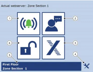
3.2 Start screen functions
Fig. 24: Start screen 1 Display alarms
2 Change display language 3 Display TROX GmbH website 4 Display the service screen 5 Zone overview
6 Log in to the webserver
Once you have logged in to the webserver ( Ä 3.4
‘Logging in to the webserver’ on page 48 ), the Start screen displays ( Fig. 24 ).
On the Start screen you can select the following func- tions by clicking the respective button ( Fig. 24 /1 – 6).
Display alarms
( Ä 4.6.5 ‘Displaying alarms’ on page 87 )
Change display language
( Ä 3.3 ‘Selecting a language’ on page 47 )
Display TROX GmbH website
Displaying the service screen
( Ä 3.6 ‘Displaying the service screen’
on page 49 )
Zone overview
( Ä 3.7 ‘Zone overview’ on page 50 )
Log in to the webserver
( Ä 3.4 ‘Logging in to the webserver’
on page 48 )
The table Ä ‘Menu structure’ on page 47 shows the menu structure of the webserver. The menu structure shows you where to find each function.
Start screen functions
Menu structure
Start screen Submenu 1 Submenu 2 Submenu 3
Displaying alarms Ä 4.6.5 ‘Displaying
alarms’ on page 87 – –
Ä 3.3 ‘Selecting a lan-
guage’ on page 47 – – –
Ä 3.4 ‘Logging in to the
webserver’ on page 48 – – –
Info – – –
Zone master settings Ä 3.7 ‘Zone overview’
on page 50 Ä 3.8.9 ‘Setting zone
values’ on page 58 –
Ä 3.6 ‘Displaying the service screen’
on page 49
Ä 3.8.1 ‘Activating the device detection mode’
on page 51
Ä 3.8.3 ‘Setting the volume flow rate’
on page 54
Ä 3.8.4 ‘Checking the volume flow rate’
on page 54 Ä 3.8.5 ‘Setting up a
supply branch’
on page 55 Ä 3.8.6 ‘Setting up an
extract branch’
on page 56 Ä 3.8.10 ‘Configuring the
zone master’ on page 65 – –
AHU – –
BACnet – –
Ä 3.8.11 ‘Summer and winter compensation’
on page 71
– –
Ä 3.5 ‘Setting date and time on the webserver’
on page 49
– –
Ä 3.8.12 ‘Network con- nection settings’
on page 71
– –
Display TROX GmbH web-
site – –
3.3 Selecting a language
The ‘Language’ ( Fig. 25 ) screen allows you to select one of the following languages:
Danish
English
German
Swedish
Norwegian
Polish
Russian
1. On the ‘Start’ screen ( Ä 3.2 ‘Start screen func- tions’ on page 46 ), click on the button for
‘Language’.
ð The ‘Language’ screen ( Fig. 25 ) displays.
Selecting a language
Fig. 25: Selecting a language 2. Select a language.
ð The display language for the webserver is set accordingly.
3.4 Logging in to the webserver
The configuration and setting of X-AIRCONTROL requires you to log in to the webserver with your pass- word. The default password is 'Service'. Displaying system settings does not require you to log in with your password.
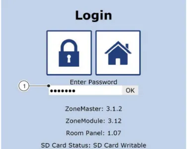
1. On the ‘Start’ screen ( Ä 3.2 ‘Start screen func- tions’ on page 46 ), click on the padlock symbol.
ð The ‘Login’ screen ( Fig. 26 ) displays.
Fig. 26: Login
2. Enter the default password 'Service' into the entry field ( Fig. 26 /1).
3. Confirm your entry with ‘OK’ or press the Enter key on your keyboard.
Fig. 27: You have been logged in
ð The Start screen shows an open padlock ( Fig. 26 /1). You can now access the Service screen ( Fig. 27 /2) for configuration and set- tings.
Logging in to the webserver
3.5 Setting date and time on the web- server
The ‘Time and Date’ screen ( Fig. 28 ) allows you to set the current time and date manually or to have them set automatically. Automatic setting means that the time and date of the zone master are synchronised with the time and date of your notebook or personal computer.
1. Log in to the webserver ( Ä 3.4 ‘Logging in to the webserver’ on page 48 ).
2. On the Start screen ( Ä 3.2 ‘Start screen func- tions’ on page 46 ), click on the ‘Tools’ symbol.
ð The Service screen displays.
3. Click on the clock symbol.
ð The ‘Time and Date’ screen ( Fig. 28 ) dis- plays.
Fig. 28: Time and date
4. If you want to activate summer time (daylight saving time), check the appropriate box ( Fig. 28 /4).
Setting date and time automatically 5. Click on ‘PC time’ ( Fig. 28 /6).
6. Click on ‘Save’ ( Fig. 28 /7).
ð Date and time have been synchronised with the PC date and time.
4. Enter the current time ( Fig. 28 /5).
5. Click on ‘Save’ ( Fig. 28 /7).
ð Date and time have been set.
3.6 Displaying the service screen
On the ‘Start’ screen ( Ä 3.2 ‘Start screen func- tions’ on page 46 ), click on the Tools symbol.
ð The Service screen ( Fig. 29 ) displays.
Fig. 29: Service
From the ‘Setup’ screen the following functions are available when you click the respective button ( Fig. 29 /1 – 9).
Displaying zone setup ( Fig. 29 /1)
( Ä 3.8.1 ‘Activating the device detection mode’
on page 51 )
( Ä 3.8.2 ‘Configuring actuators and sensors’
on page 53 )
Configuring the zone master ( Fig. 29 /2) ( Ä 3.8.10 ‘Configuring the zone master’
on page 65 )
Displaying the service screen
Setting summer and winter compensation ( Fig. 29 /4)
( Ä 3.8.11 ‘Summer and winter compensation’
on page 71 )
Configuring zone master network settings ( Fig. 29 /5)
Connecting X-AIRCONTROL to an air handling unit using the Modbus RTU protocol ( Fig. 29 /6) ( Ä 6 ‘Integrating X-AIRCONTROL with a central BMS’ on page 90 )
Integrating X-AIRCONTROL with a central BMS using the BACnet protocol ( Fig. 29 /7)
( Ä 6 ‘Integrating X-AIRCONTROL with a central BMS’ on page 90 )
Setting date and time on the webserver ( Fig. 29 /8) ( Ä 3.5 ‘Setting date and time on the webserver’
on page 49 )
Displaying system information ( Fig. 29 /9)
3.7 Zone overview
On the ‘Start’ screen ( Ä 3.2 ‘Start screen func- tions’ on page 46 ), click on the button for zone overview.
ð The ‘Zone Overview’ screen ( Fig. 30 ) dis- plays.
Fig. 30: Zone overview
From the ‘Zone Overview’ screen the following func- tions are available when you click on the respective button ( Fig. 30 /1 – 5). The screen shows only zones whose zone modules have been detected by the zone master ( Fig. 30 /4).
Displaying the Start screen ( Fig. 30 /2)
( Ä 3.2 ‘Start screen functions’ on page 46 )
Displaying zone settings ( Fig. 30 /4)
( Ä 3.8.9 ‘Setting zone values’ on page 58 )
Displaying zone setup ( Fig. 30 /3)
( Ä 3.8 ‘Configuring zone modules’ on page 51 )
Finding zone modules ( Fig. 30 /5)
( Ä ‘Finding zone modules’ on page 50 )
Displaying alarms ( Fig. 30 /1)
( Ä 4.6.5 ‘Displaying alarms’ on page 87 ) Finding zone modules
The loudspeaker buttons ( Fig. 30 /5) allow you to have zone modules emit a sound so that you can easily detect them.
Click on the loudspeaker symbol ( Fig. 30 /5) for a zone module.
ð The zone module will emit a sound such that you can detect it.
Zone overview
3.8 Configuring zone modules
3.8.1 Activating the device detection mode
The ‘Zone Setup’ screen ( Fig. 31 ) allows you to automatically detect the sensors and actuators that are connected to zone modules. This automatic configuration also allows you to deactivate individual sensors or actuators while the system is in operation; no fault will be generated. You can adjust the components for each zone module when you carry out configuration manually ( Ä 3.8.2 ‘Configuring actuators and sensors’ on page 53 ).
If during manual or automatic zone setup either 'Modbus' or 'MP bus' is displayed after an actuator or a sensor, this means that a component on the bus has been detected. Components that have not been connected and that are hence not part of the bus system should be deactivated during commissioning as otherwise they may generate faults.
Automatic detection of connected components
Module X-AIR-ZMO-ANA X-AIR-ZMO-MP X-AIR-ZMO-MOD Detection Autom. Manually Autom. Manually Autom. Manually Supply air volume flow con-
troller Fig. 33 /4 X X X
Extract air volume flow con-
troller Fig. 33 /5 X X X
Heating valve actuator Fig. 33 /6 X X X
Cooling valve actuator Fig. 33 /7 X X X
Window contact Fig. 33 /8 X X X
Frost protection sensor Fig. 33 /9 X X X
Motion detector (PIR
sensor) Fig. 33 /10 X X X
Room temperature sensor Fig. 33 /11 X X X1
Supply air temperature
sensor Fig. 33 /12 X X X1
Setpoint value adjuster Fig. 33 /13 X X X
CO2/VOC sensor Fig. 33 /14 X X X X
Humidity sensor Fig. 33 /15 X X X
1) If the system detects a room temperature sensor on the 'Modbus sensor' connection, the PT1000 room tempera- ture sensor connected to the RJ12 socket ( Fig. 8 /7: terminal 3) becomes a supply air sensor.
1. Log in to the webserver ( Ä 3.4 ‘Logging in to the webserver’ on page 48 ).
2. On the Start screen ( Ä 3.2 ‘Start screen func- tions’ on page 46 ), click on the Tools symbol for a zone section.
ð The Service screen displays.
3. On the ‘Service screen’, click on ‘Zone Setup’.
ð Automatic actuator and sensor detection has been enabled ( Fig. 31 ).
Configuring zone modules > Activating the device detection mode
When the automatic detection of actuators and sensors is complete, the screen is updated ( Fig. 31 ) and shows the actuators and sen- sors connected to the zone modules. Auto- matic configuration does not allow you to make any adjustments manually.
Fig. 32: Actuators and sensors 5. Click on ‘Save’ ( Fig. 31 /1).
ð Actor and sensor data for the zone master has been saved.
Configuring zone modules > Activating the device detection mode
3.8.2 Configuring actuators and sensors
Fig. 33: Manual zone setup 1 Section
2 Zone 3 Save
4 Supply air flow rate 5 Extract air flow rate 6 Heating
7 Cooling
8 Window contact
9 Frost protection sensor 10 Motion detector (PIR) 11 Room air temperature 12 Supply air temperature
13 Analogue setpoint value adjuster 14 CO2/VOC
15 Humidity
The ‘Zone Setup’ screen ( Fig. 33 ) allows you to configure the actuators and sensors that are connected to the zone modules. During operation the connected actuators and sensors are monitored such that hardware problems and connection errors will be detected.
The table Ä on page 51 shows the actuators and sensors that are automatically detected or which have to be activated or deactivated manually during commissioning.
1. Log in to the webserver ( Ä 3.4 ‘Logging in to the webserver’ on page 48 ).
Configuring zone modules > Configuring actuators and sensors
3. Activate or deactivate actuators and sensors ( Fig. 33 /4 –15) for individual zone modules.
4. Enter a name for each zone module ( Fig. 33 /2).
5. Enter a name for the zone master (section) ( Fig. 33 /1).
6. Click on ‘Save’ ( Fig. 33 /3).
ð The configuration of each zone module has been saved.
3.8.3 Setting the volume flow rate
The ‘Air Volume Setup’ screen ( Fig. 35 ) allows you to set supply air and extract air volume flow rates for ana- logue zone modules. You can also assign several zone modules to one extract air controller. If zone modules do not have individual, dedicated extract air controllers yo