The ideas presented herein are the joint product of the MIT Transit Project led by Dr. Knight and provided many of the seed ideas that formed the basis of our work. Preliminary work with the MIT Connection Machine Project and with the Symbolics VLSI group highlighted many of the issues and ideas that the Transit Project had inherited.
Collaboration with Tom Leighton, Bruce Maggs, and Charles Leiserson on interconnection topologies also helped develop many of the ideas presented here.
List of Tables
Introduction and Background
Introduction
- Goals
- Scope
- Overview
- Routing
- Fault Management
- Organization
Regardless of the exact network topology used for communication, both the number of switching components and the amount of wires inside the network are at least linear in the number of processors supported by the network. Switching Latency – the number of switches, and to some extent the length of the wires, which must be crossed between nodes in the network. Versatility – the extent to which the network can be adapted to a wide range of applications.
We also need a routing scheme that is able to efficiently utilize the network's capabilities.
Background
- Models .1 Fault Model
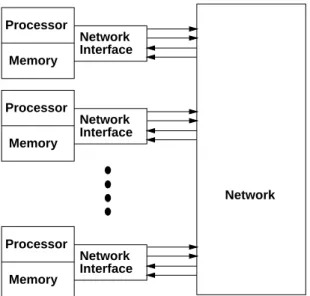
- Multiprocessor Model
- IEEE-1149.1-1990 TAP
- Effects of Latency 1
- Latency Issues
- Network Latency
- Locality
- Node Handling Latency
- Faults in Large-Systems
- Fault Tolerance
- Pragmatic Considerations
- Physical Constraints
- Design Complexity
- Flexibility Concerns
For the sake of presentation here, we limit our concern to errors within the network itself. Transmission time (Ttransmit): The time required to transmit the entire contents of a message to or from the network. Transit latency is the quotient of physical distance and speed of signal propagation.
Transfer time represents the amount of time it takes to transfer all the data of a message to or from the network.
Engineering Reliable, Low-Latency Networks
Network Organization
- Low-Latency Networks .1 Fully Connected Network
- Full Crossbar
- Hypercube
- k -ary- n -cube
- Tree Based Networks
- Express Cubes
- Summary
- Wire Length
- Fault Tolerance
- Indirect Routing
- k -ary- n -cubes and Express Cubes
- Multiple Networks
- Extra-Stage, Multistage Networks
- Interwired, Multipath, Multistage Networks
- Robust Networks for Low-Latency Communications
- Network Design
- Parameters in Network Construction
- Endpoints
- Trees
- Hybrid Fat-Tree Networks
- Flexibility
- Summary
- Areas to Explore
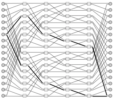
Beyond the center of the network, the sorting function performed by the network limits the number of routers in the path to the desired destination. For example, notice in the network shown in Figure 3.11 that dilation-1 routers are used in the final stage of the network. Once Equation 3.4 is solved virs0, we can quantify the number of connections in each phase of the network by Equation 3.5.
For each network, the return probability of the network is plotted against the number of uni-.
Routing Protocol
- Problem Statement
- Flexiblity
- Distributed Routing
- Dynamic Fault Tolerance
- Fault Identification
- Protocol Overview
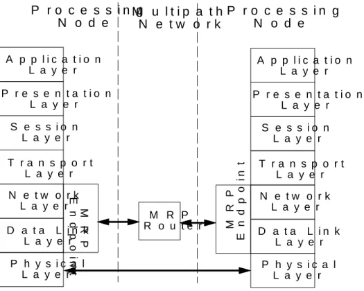
- MRP in the Context of the ISO OSI Reference Model
- Terminology
- Signalling
- Connection States
- Router Behavior Idle port
- Making Connections
- Basic Endpoint Protocol
- Initiating a Connection
- Return Data from Network
- Receiving Data from Network
- Composite Behavior and Examples
- Examples
- Avoiding Known Faults
- Performance
- Pipelining Data Through Routers
- Pipelined Connection Setup
- Pipelining Bits on Wires
- Width Cascading Problem
- Techniques
- Costs and Implementation Issues
- Protocol Features
- Overhead
- Flexibility
- Distributed Routing
- Fault Tolerance
- Fault Identification and Localization
- Summary
- Areas to Explore
- Dealing with Faults
- Scan-Based Testing and Reconfiguration
- Robust and Fine-Grained Scan Techniques
- Multi-TAP
- Port-by-Port Selection
- Partial-External Scan
- Fault Identification
- Reconfiguration .1 Fault Masking
- Propagating Reconfiguration
- On-Line Repair
- High-Level Fault and Repair Management
- Areas To Explore
Although a routing protocol that can properly handle dynamic errors can tolerate unidentified errors in the system, the performance of the routing protocol can be further improved by identifying static errors and reconfiguring the network to avoid them. Fault identification also enables determining the extent of faults in the system. The faster the errors can be identified and the system can be reconfigured, the less impact the errors will have on network performance.
When all routers along the path are reversed, data can flow back from the destination to the source. This means that MRP itself is independent of the underlying physical layer that handles raw bit transfers. MRP is therefore independent of the electrical and mechanical aspects of the interconnection. MRP-ROUTER and MRP-ENDPOINT are required to fully fulfill the role of data link layer.
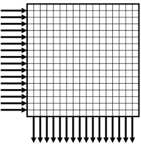
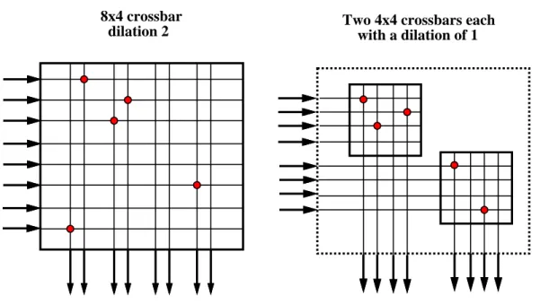
Recall from Chapter 3 that a crossbar has a set of inputs and a set of outputs and can connect any input to any output with the restriction that only one input can be connected to each output at any time. When connections are requested through a router, there is no guarantee that connections can be established. As long as the dilation of the router is less than the number of input channels to the router (ie, d < i), it is possible that multiple links will want to connect in a particular logical direction, such as logically equivalent outputs.
That is, the direction of data transmission can be changed so that the data flows from the original destination to the original source. Words sent over network connections can be classified as data words and signal words. In this section, we describe the essential behavior of the router signaling protocol from the point of view of a single pair of routing components.
The states of a forward-reverse gate pair can be described by a simple finite state machine.
Signalling Technology
- Signalling Problem
- Transmission Line Review
- Issues in Transmission Line Signalling
- Basic Signalling Strategy
- Receiver
- Circuitry
- Impedance Selection Problem
- Register Sizes
- Sample Results
- Sharing
- Simulating Long Sample Registers
- Areas to Explore
Packaging Technology
- Packaging Requirements
- Packing and Interconnect Technology Review .1 Integrated Circuit Packaging
- Printed-Circuit Boards
- Connectors
- Dual-Sided Pad-Grid Arrays
- Compressional Board-to-Package Connectors
- Printed Circuit Boards
- Assembly
- Repair
- Stack Packaging of Non-DSPGA Components
- Network Packaging Example
- Packaging Large Systems .1 Single Stack Limitations
- Fat-tree Building Blocks
- Hollow Cube
- Wiring Hollow Cubes
- Hollow Cube Support
- Hollow Cube Limitations
- Multi-Chip Modules Prospects
- Summary
- Areas To Explore
We can collect the (r;1)down-directing degree, the related up-directing degree, and the cross-connect ions at the physical level of the three levels. If we consider the (r;1)low n n t r e s t e v n age, the overall sorting performed by physical level three is given in Equation 7.1. The size of a logical node at each level of the physical tree will increase as you move toward the root, as the width at each level increases toward the root.
As a result, we must further decompose each physical level of the tree into a primitive unit that can be assembled to handle the different width requirements at each level. We use the thermal unit tree to refer to any implementation-defined primitive structure of the standard. b slice width of each level of the physical tree. Instead, we can use 328 = 4 UT648 unit trees to build the root of each subtree rooted in the second physical level of the tree to support the same number of nodes and first level unit trees.
Shown here is an example where the device trees in the two physical tree levels show that they are the same size. If the tree is part of the physical tree level, the pages contain entity trees that are part of the physical tree level;1. Shown here is an example where the device trees in the higher physical tree level are four times as large as those in the lower physical tree level.
With the right fanout across the device, tree stacks can be removed from the non-leafed, physical tree levels and the network still maintains sufficient connectivity to carry all connections. Due to the physical size of the hollow cubes, they occupy room-sized or building-sized structures.

Case Studies
RN1 is a circuit-switched routing element developed in the MIT Transit Project [MDK91]. In both configurations, RN1 supports the basic routing protocol described in section 4.5. Each forward and reverse port contains a simple finite e-st ate engine for maintaining link status and processing protocol signaling.
The line control units keep track of the available reverse ports and other random port selection. Backward gate arb it ratio occurs in a distributed fashion along each logical output column. When multiple forward ports attempt to open a connection to the same logical reverse port during the same cycle, an 8-way arb it relationship occurs for the available reverse port.
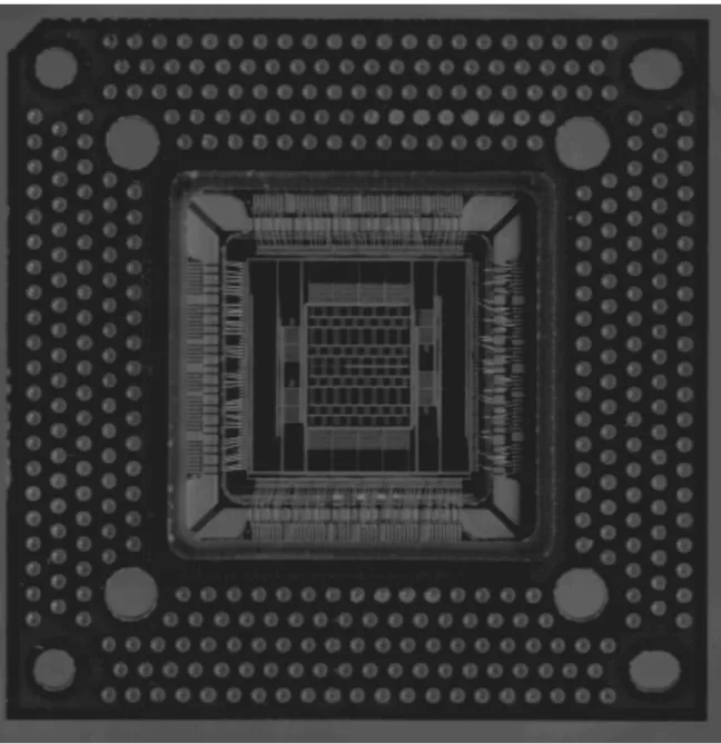
Min91] contains a detailed description of the design and implementation at ion of RN1. RN1 is implemented as a custom, CMOS integrated circuit using a combination of standard cell and custom layout. Standard, five-volt, CMOS i/o pads were used with the first-generation routing component.
CROSSPOINT
ARRAY
- Metro
- METRO Architectural Options
- METRO Technology Projections
- Modular Bootstrapping Transit Architecture (MBTA)
- Architecture
- Performance
- Metro Link
- MLINK Function
- Interfaces
- Primitive Network Operations
- MBTA Packaging
- Network Packaging
- Node Packaging
- Signal Connectivity
- Assembled Stack
Each processing node h as net work input and t w net work sets s (ni =no=2) for fault tolerance. The network work consists of the RN1 routing component and uses the ion-1 extension route configuration. The service of four logical network interfaces of connect ion and network connection outside the network work.
The MBTA arc it ecture is balanced to support wide network connections running at 100 MHz. The netw ork interfaces send data from the fast, static memory and also receive data to the memory. Here you can see the netw ork for a 64-processor MBTA machine composed of RN1 routing components.
The processor is responsible for initiating packets and originating message queues while the network port is busy. Network packing is a simple network packing mapping application introduced in Section 7.4. Each node must be connected to two network input channels and two network output channels.
This segregation leaves us with eight layers of nodes on each side of the network. Each of the eight nodes taps from the appropriate subset of these signals to connect to the network.
Conclusion
Summary and Conclusion
- Latency Review
- Fault Tolerance Review
- Integrated Solutions
We have examined the relation of latency and fault tolerance with large, multiprocessor networks. Mouse, we found common cues that reduce latency and improve fault tolerance. Consequently, we were able to identify a rich class of net jobs with good latency and fault tolerance.
By combining and collapsing the lagged contributions from Section 2.4 into a single equation, we become We see that there are many aspects that contribute to just work delay. In Chapters 3 through roughly 7, we addressed all of these latency components and explored ways to minimize their contributions.
We have not considered that the latency contributed by each routing component is composed of the switching time and the I/O latency. We have seen that increasing the bandwidth available for each connection will reduce transmission latency. Furthermore, we saw that content latency stems from inadequate or improperly used resources within the network.
This freedom reduces the likelihood that blocking will occur within the network work and thus content latency. In Section 4.9.2 we saw how fast path collapse further reduced content latency by quickly reclaiming resources allocated to blocked.
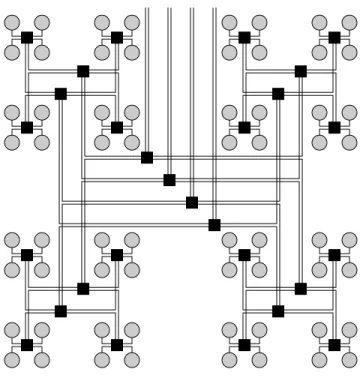


![Figure 3.11: 16 16 Multibutterfly Network [Lei85].](https://thumb-us.123doks.com/thumbv2/123pdforg/7656167.43617/43.918.285.621.145.452/figure-3-11-16-16-multibutterfly-network-lei85.webp)