I would like to thank Chratien Mak who helped me with a number of tasks from the initial stages of this project to its completion. I would like to thank Pamela Liang for her constant support throughout this project and for helping with the proofreading of this thesis report.
Introduction
Problem Statement
Much experimental research has been conducted to understand the bond behavior of FRP rebars in concrete. Since then, many studies have been conducted to evaluate the effects of various parameters on the adhesion of FRP rebars.
Research Objectives
The use of HPC and UHPC in conjunction with FRP materials requires modifications to the current design equations and provisions that determine the bond strength of FRP bars and the required length of their development. The changes are necessary to account for the effect of using HPC and UHPC on the bond properties between these materials.
Thesis Overview
As the demand for stronger and more durable structures increases, high-performance concrete and ultra-high-performance concrete have been implemented as an alternative to conventional concrete for construction. These modifications should be able to reduce the amount of FRP reinforcement required, which in turn will reduce the overall cost of the structure.
Background, Literature Review, and Design Codes
Fibre Reinforced Polymers
- Resins
- Fibres
- Manufacturing Process
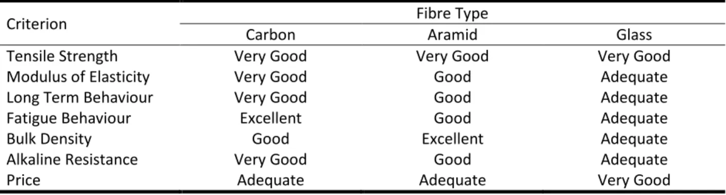
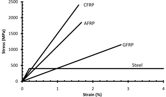
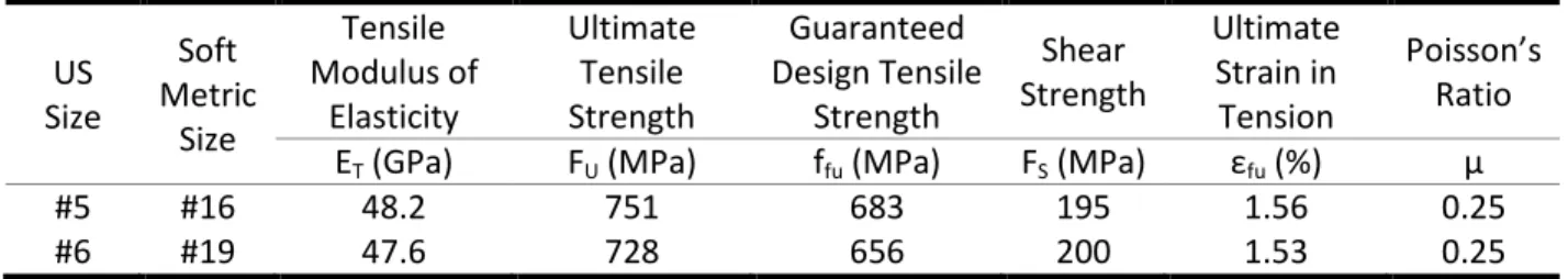
- Properties of FRP
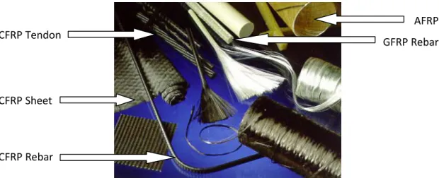
- Applications of FRPs in Construction
FRPs made from aramid fibers have low compressive and shear strengths due to the anisotropic properties of the fibers. The mechanical properties of FRPs are highly direction dependent, so the properties typically specified are in the direction of the fibers.

Bond Mechanism
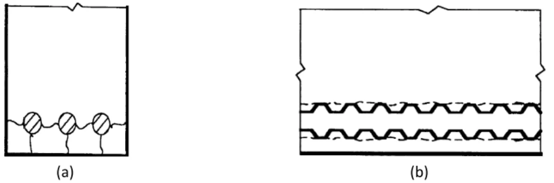
- Bond Failure Modes
- Bond Test Specimens
- Bond Behaviour of Steel Rebars
- Bond Behaviour of FRP Rebars
The explanation is that the surrounding concrete around the reinforcement in the tensile test is under compression, reducing cracking and therefore increasing the bond strength. Conversely, in beam tests, the concrete surrounding the reinforcement is under tension, leading to low stress cracking and therefore reducing the bond strength.
Factors Affecting Bond of FRP Rebars in Concrete
- Bar Properties
- Structural Characteristics
- Concrete Properties
The trials of Ehsani et al. 1993) showed that the bond strength of the upper bars is 66% of the bond strength of the lower bars. It was found that the increase in bond strength is proportional to the square root of the compressive strength of concrete.
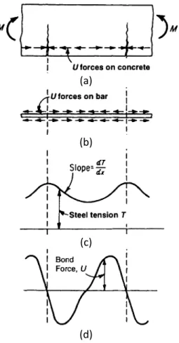
Determination of Bond Strength
It is clear that the bond behavior depends on the mechanical properties of the FRP strip ribs. The actual distribution of bond forces along the length of the bar cannot be determined because they depend on the location of flexural cracks and the amount of tensile load separated from the concrete—neither of which can be estimated.
Bond Strength and Development Length Equations in Design Codes
- CSA S806-02
- CSA S6-06
- ACI 440.1R-06
- JSCE Design Recommendation
Equation 2.4 shows that bond stress is a function of concrete cover, concrete compressive strength, bar diameter, bar location, concrete density, fiber type, and bar surface profile. According to the JSCE Design Recommendation, Equation 2.10 shows that the bond strength between FRP bars and concrete depends on the location of the bar, the compressive strength of the concrete, the concrete cover, the diameter of the bar, and the restraint provided by the transverse reinforcement.
Bond Stress-Slip
- Malvar Model
- Bertero, Popov, and Eligehausen Model (BPE Model)
- Cosenza, Manfredi, and Realfonzo Model (CMR Model)
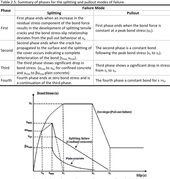
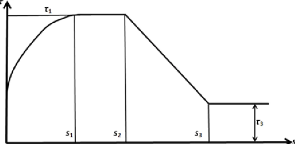
The well-known bond stress slip analytical law for deformed steel bars that fail by pulling out the bar was proposed by Eligehausen et al. According to this model, the bond stress slip of steel bars shows four distinct branches (Figure 2.15): the initial rising branch of the bond stress slip relationship up to the maximum bond stress,τ1, for s≤s1; a second branch from constant bond (τ=τ1) to sliding (s = s1); a linearly descending branch from (s2,𝜏1) to (s3,𝜏3); and a horizontal branch for s > s3 with a value of τ equal to the development of friction (τ=τ3). Application of the BPE model to FRP bars was done by Faoro (1992), Aluno Rossetti et al.
Since most structural problems must be addressed at the service state level, improved modeling of the bond stress-slip curve is required for the ascending branch only (Cosenza et al., 1997).
Experimental Investigation
Introduction
Experimental Program
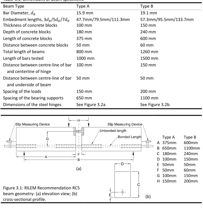
- Beam Specimen Geometry and Configuration
- Pullout Specimen Geometry and Configuration
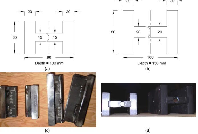
The following reasons to justify the reduction of auxiliary reinforcement provided in the beam specimens:. Finally, the compressive strength of the concrete used in the RILEM/CEB/FIP Recommendation for beam specimens is between 23-33 MPa, depending on the dimensions of the control specimens. The configuration of the tensile specimens used in this study was based on Annex D of CSA S806-02.
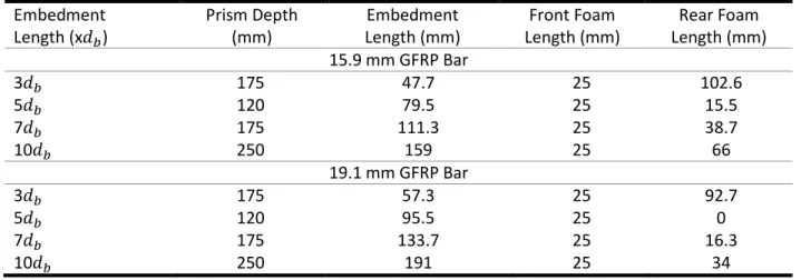
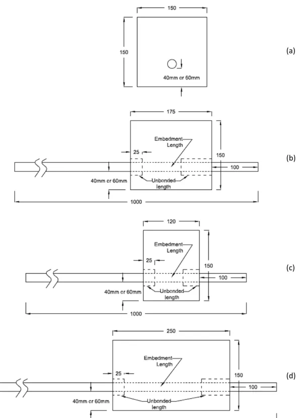
The dimensions of the pull-out test specimens were dependent on the embedment length of the reinforcement being tested.
Materials
- GFRP Rebar
- Commercial Concrete
- Ryerson Concrete Mix
Two commercial concretes were selected for use in the production of adhesion specimens: HP-S10 and Ductal® concrete. HP-S10 concrete was used to provide compressive strength at the lower end of the study range and Ductal® was used to provide compressive strength at the higher end of the study range. The development of the compressive strength of HP-S10 concrete was determined from control rolls produced during the casting of the adhesion test specimens.
After completing the mixing sequence, the concrete was poured into the bond test specimens.

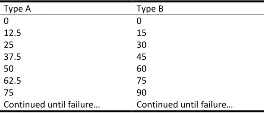
Test Setup and Procedure
- Beam Test
- Pullout Test
The amount or torque was limited so that the transverse strength of the GFRP bar could not. In addition to the fabricated grip, a wedge-shaped grip was placed at the end of the specimen to provide additional strength. If the wedge grip was not used, the fabricated grip was placed at the far end of the GFRP rod and spacers were used as needed.
A data acquisition system was used to record data from the load cell, which measures the applied load to the nearest 0.01 kN, and from the LVDT located at the free end of the pull-out sample, which measures the free end slip yielded with an accuracy of 0.01 mm.
Results and Analysis
General
Beam Test Specimen Results
- Stress vs. Strain Curve for GFRP Rebar
- Stress vs. Slip Curve for Beam Test
By dividing the tensile load by the rebar area, the bar stress 𝑓𝑠 was obtained for each specimen. The strain values of GFRP at bond failure from the strain gauges are shown in Appendix C. The maximum strain reached was much lower than the ultimate stress of the reinforcement, so it can be concluded that all beam tests failed due to failure of the bond and not due to rupture of the armature.
The stress-slip curves of the beam specimens will be used in the subsequent chapter to determine the required development length for the GFRP bars used in this study.

Pullout Test Specimen Results
- Stress vs. Slip Curve for Pullout Specimen
Similar to Figure 4.9, grouping the samples in Figure 4.21 and Figure 4.22 makes it easier to observe any trends present in the data. The trends in Figure 4.21 and Figure 4.22 in terms of concrete strength, bar diameter and embedment length and concrete cover will be discussed in Section 4.4. The bond stress-slip curves shown in Figure 4.23 are for pull-out specimens that failed due to reinforcement pull-out, not splitting.
Similar to the beam test specimens, from the joint stress-slip curves for the pull-out specimens (Figure 4.23), it was found that brittle failure of the GFRP rebars occurred due to the sudden yielding of the sand coating.
Parameter Analysis
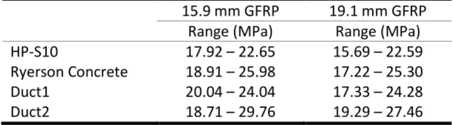
- Effect of Concrete Compressive Strength
- Effect of Bar Diameter
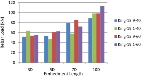
- Effect of Embedment Length
- Effect of Concrete Cover
This indicated that the hydrostatic pressure affected the bond strength uniformly over the different embedment lengths. The effect of rod diameter for the pull-out samples remains unclear on bond strength. An average bond strength reduction of 6% was observed for the beam specimens cast with HP-S10 concrete.
This indicated that the confinement of the concrete supply did not influence the effect of the embedment length on the bond strength.
Summary
Development Length Modeling and Code Requirements
- General
- Modeling of Bond Stress-Slip Relationship
- Determination of Development Length
- Comparison to Code Predictions
- CSA S806-02 Development Length
- CSA S6-06 Development Length
- ACI 440.1-06 Development Length
- JSCE Development Length
- Experimental Results and Design Code Requirements
- Development Length From Pullout Tests
- CSA S806-02 Bond Strength
- CSA S6-06 Bond Strength
- ACI 440.1-06 Bond Strength
- JSCE Bond Strength
- Experimental Bond Strength and Design Code Bond Strength
From the values in Table 5.1 it is possible to determine the required development length on the GFRP bars used in this study. Based on Equation 5.1, the required development length was determined for the GFRP bars used in this study. Using Equation 2.8, the development length was first determined and then substituted into Equation 2.7 to determine the bond strength.
The bond strength achieved by FRP bars from the JSCE recommendation can be determined using equation 2.10.

Conclusion
General
Therefore, it can be concluded that the compressive strength of concrete has no influence on the bond strength of GFRP bars in high-strength and ultra-high-strength concrete. The addition of fibers to the concrete created a local disturbance at the bond interface, which consequently reduced the bond strength. As the coverage was increased, the amount of confinement from the concrete was increased and as a result the bond strength was increased.
Due to the addition of fibers, the concrete cover had no influence on the bond strength of the fiberglass rods.
Limitations of the Study
The results from the beam specimens allowed the derivation of a bond stress-slip law, which was used to model the test results and determine the development length requirement. It was determined that the development lengths provided by CSA S806-02, CSA S6-06 and the JSCE Design Recommendation can be reduced by 20% provided there is sufficient transverse reinforcement around the bar being developed so that the addition of reinforcement additional crossbars should not affect the bond strength. This reduction would still maintain a safety factor of two over the development length determined by the test results.
Although the bond strengths of the code predictions were less than the bond strengths of the pull-out tests, a reduction factor could not be applied as it was unclear to what extent the development lengths could be reduced.
Recommendations for Future Work
The slump flow is an indication of the filling capacity of the self-compacting concrete. The cone was lifted vertically in one movement without interfering with the flow of the concrete. A straight edge was used to knock the concrete off the top of the funnel so that it was flush with the top of the funnel.
The gate was then lifted and the concrete flowed into the horizontal part of the box.