78 Figure 8.3.1 Axial stiffness graph results from FE analysis and experimental study for Level II (excluding construct 4). 81 Figure 8.3.2 Presentation of results from FE analysis and experimental study for Construct 5 in Level II condition.
INTRODUCTION
The experimental study was then used to validate a finite element model of the periprosthetic femur and bone plate combination. The model was created with particular interest given to the predicted stiffness under various gap widths as well as the deformation measured at the proximal end of the femur fracture.
MOTIVATION
Since compressive stress is required to maintain healthy bone density, stress shielding often results in a lower bone density and higher porosity compared to the preoperative bone [9]. Bone fixation methods must be chosen carefully to minimize the risk of refracture by optimizing the compressive stresses transmitted to the femur to maintain healthy bone density.
THE HUMAN FEMUR
- Anatomy
- Co-ordinate Planes for the Human Body
- Human Femur
- Hip Joint
- Knee Joint
- Femur Fracture: Clinical Aspects
- Bone Disease
- Physical Impact
- Motor Vehicle Accident
- Symptoms
- Biomechanics
- Human Gait Cycle
- Femur Fractures: Biomechanical Aspects
- Material Properties of Bone
Both the lateral condyle and the medial condyle are located at the distal end of the femur. A proximal femur fracture is a fracture that occurs to the bulbous upper part of the femur closest to the hip.
![Figure 3.1.2 Human anatomy of lower limb [22]](https://thumb-us.123doks.com/thumbv2/9docorg/12428440.0/24.918.362.556.563.984/figure-3-1-human-anatomy-lower-limb-22.webp)
METHODS OF FEMUR FRACTURE FIXATION
Nonsurgical Methods of Fracture Fixation
- Traction
- Casting
If the fracture is associated with fragments or comminution, casting will not work because it is unable to remove the fragments or maintain proper alignment. The remaining fragments or reduction in size can also cause further complications such as infection in the injured area [2].
Surgical Methods of Fracture Fixation
- External Fixation
- Intramedullary Fixation
- Plating
- Benefits of Plate Fixation
- Limitations of Plate Fixation
The bone plate is then attached to the other side of the bone break and the external traction force is removed. This plate exerts a force on the bone in a direction perpendicular to the plate surface [6].
![Figure 4.2.1 External fixation: (a) illustration demonstrating application [53], (b) x-ray picture showing fracture of femur fixed with external fixator [54]](https://thumb-us.123doks.com/thumbv2/9docorg/12428440.0/40.918.180.764.103.528/figure-external-fixation-illustration-demonstrating-application-fracture-external.webp)
CURRENT STUDY
Problem Statement
Research Objective
Primary Goals of this Study
Research relevant literature on femoral anatomy, lower extremity biomechanics, causes of femoral failure, and various femoral fixation methods and procedures. The literature was also reviewed on the topic of stress shielding and its prevention, particularly in relation to in vivo and in vitro experimental studies in long bone/femur fixation. Conduct an experimental study of the load transfer characteristics of 5 different metallic bone fixation constructs used to fix a simple midshaft femoral fracture.
Develop the 3D geometry of the femur and bone plates using a CAD model and create a finite element analysis (FEA) of the 5 femur and metal bone plate systems used in the experimental study. The FEA model results would then be validated by comparison with experimental results.
EXPERIMENTAL STUDY
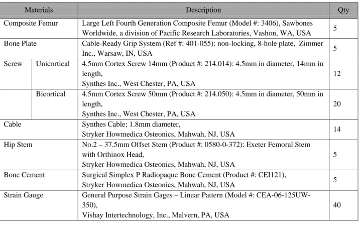
Material Selection
- Composite Femur
- Bone Plate and Cable
- Bone Screws
- Hip Stem
- Strain Gauges
Each system was supplied with a bone plate consisting of 8 non-locking holes (i.e., unthreaded screw holes). Depending on the biological condition of the bone, a unicortical or a bicortical screw can be inserted through the screw hole. When the immediate area of bone beneath the bone plate is large in diameter and free from fractures and cracks, a bicortical screw can be used.
Since each femur has its own unique profile, it is common practice for a surgeon to modify the bone plate before installing it during surgery. This is done so that the bone plate profile matches the profile of the injured femur as closely as possible. In this study, a manual bone plate bending machine was used to adjust the profile of each bone plate using standard surgical procedures (Figure 6.1.3).
The bone plate was then attached to the proximal part of the femur using various screws and cables.
![Figure 6.1.1 Large left Fourth Generation Composite Femur [65]](https://thumb-us.123doks.com/thumbv2/9docorg/12428440.0/54.918.130.549.117.350/figure-large-left-fourth-generation-composite-femur-65.webp)
Specimen Preparation
- Femur Preparation
- Three Levels of Specimen Conditions
- Five Types of Construct Design
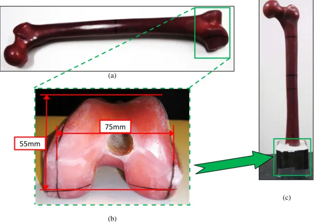
First, the proximal end of each femur was removed using an industrial band saw by cutting along a line that was 66 mm from the tip of the femoral head and approximately 35° with respect to the femoral shaft in the coronal plane. Second, the cancellous bone was removed from the incision area using a rasp so that the appropriate volume of empty space for hip stem insertion was obtained. Third, each hip stem was inserted and the bone cement (Simplex P, Stryker, Mahwah, NJ, USA) was mixed and poured into the prepared end of the femur.
After the intact femurs were tested, a transverse cut was made in the middle of the stem of each femur using a band saw. The bone plates were not moved or altered during the Level II and Level III tests. In the proximal part of the femur, cables and/or unicortical screws were used to place the bone plate.
The hardware attachment method was designed differently for each sample based on the combination and order of the hardware.
Mechanical Testing
- Axial Stiffness Test
- Lateral Stiffness Test
- Torsional Stiffness Test
- Strain Gauge Set-up
- Strain Gauge Positions
- Strain Gauge Test
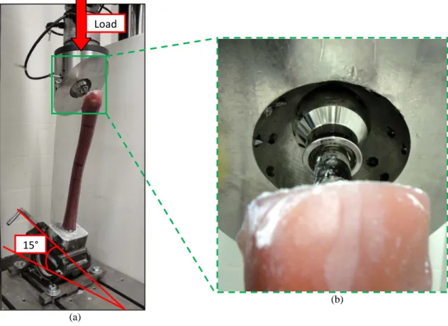
Due to the anatomical orientation of the femur, the axial load was applied away from the axis of the femoral shaft. Vertical loads were applied to the top of the femoral head at a loading rate of 5 mm/min with a preload of 50N. Finally, a load was applied to the tip of the femoral ball at a loading rate of 5 mm/min.
Second, the surface finish must be kept within the range of 1.6 – 3.2μm to allow for proper bonding of the strain gauges to the installation surface [73]. A "+" was used to locate the horizontal and vertical orientation of the gauges so that they are properly aligned. The meter is centered on the PCT-2A cellophane tape, and the outside, solder/wiring side, of the meter is then taped to the tape.
Steps 6 through 7 were repeated for each of the 8 strain gauges used installed in the 5 constructs used in this study.
FINITE ELEMENT MODELING AND ANALYSIS
- Femur
- Bone Plate and Hardware
- Material Properties
- Synthetic Bone Model
- Bone Plate, Bone Screw and Cable
- Hip Stem and Femoral Ball
- Bone Cement for Hip Stem Implantation
- Anchoring Block
- Finite Elements and Nodes
- SOLID187
- CONTA174
- TARGE170
- Boundary Conditions
- Contact
- Mesh Sensitivity and Convergence
Because the aim of the current study was to understand the mechanical performance of the femoral bone plate system, as opposed to the biological study of bone tissue, the same assumption was taken into consideration. The material properties of the 316L stainless steel are obtained from the standardized values of the American Iron and equation 7.3.3. To generate a model that most closely simulated the experimental conditions, the material property of concrete was applied to the anchor block component of the model.
The stiffness behavior of the anchor block was set as flexible in ANSYS Workbench. Since the material directions correspond to the coordinate direction of the element, the linear elasticity of the materials given in Section 7.3 [94] can be used. All contact elements in this study were set to be connected, except for the contact surface between the femoral cortical bone and the bone plate, which was simulated without separation.
All contact surfaces were modeled to be bonded except for the contact surfaces between the proximal half of the femur and the bone plate and between the distal half of the femur and the bone plate, which were set without separation (Figure 7.6).

RESULTS
- Experimental Results
- Three Modes of Loading on Level I Constructs
- Experimental Test on Constructs in Level II Fracture Condition (1mm Gap)
- Test on Constructs at Level III Fracture Condition (5mm Gap)
- Finite Element Analysis Results
- Axial Compression Stiffnesses for Level II Constructs
- Strain Values Calculated for Level II Constructs Using FE Model
- Axial Compressive Stiffnesses for Level III Constructs
- Strain Values Calculated for Level III Constructs Using FE Model
- Comparative Analysis Results
- Validation of the Finite Element Model
- Compressive Strain & Stress Shielding
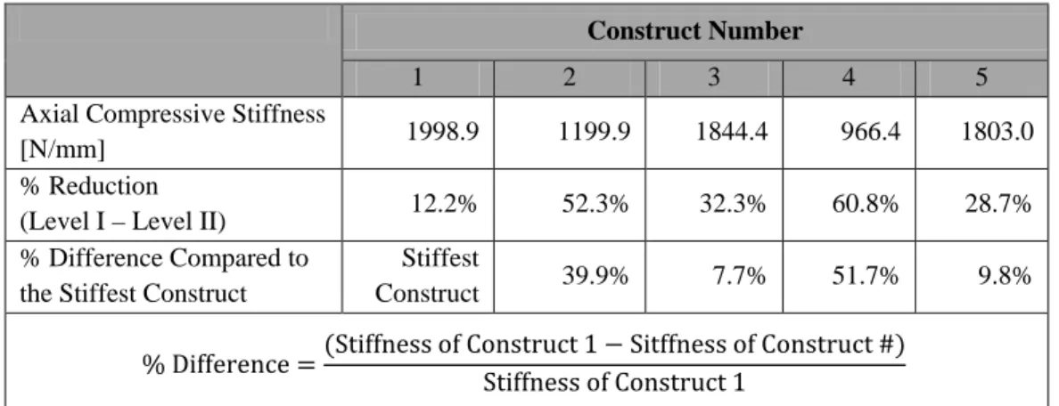
First, a comparison of the data between the finite element and the experimental results was performed. With the exception of Construct 4, the finite element program predicted the axial stiffness of each construct to within 10.3% of the observed results for the Level II condition (1 mm spacing). The correlation of the stiffness values between the finite element model and the experimental results for the Level II condition is plotted in Figure 8.3.1 without Construct 4.
Therefore, the finite element model seems to have been successful in predicting the stiffness of Level II structures. Thus the finite element program tends to overestimate the stiffness of the structures by an average of 22% in the Level III condition. In contrast to the observed results for the Level III test condition, stiffness values calculated using the finite element model predicted stiffnesses ranging from -28 to 27% of the predicted mean stiffness (Table 8.3.3).
A comparison of the experimental results and the finite element analysis showed that the finite element analysis could not accurately model the deformation at position 6 (the medial surface on the proximal side of the fracture, closest to the fracture surface).
DISCUSSION
- Summary of Important Findings from Present Study
- Comparison of Present Experiments with Previous Studies on Fracture Fixation
- Comparison of Present FEA with Previous Studies on Fracture Fixation
- Inter-comparison of Five Constructs
- Clinical and Biomechanical Implications
- Strain Distribution Due to Geometrical Characteristic of Femur
- Selection Based on Compressive Stiffness
- Selection Based on Stress Shielding
- Sources of Error and Limitation
- Future Work
In this case, 100% of the applied load was carried across the gap by the bone plate. Thus, the stiffness of the Level III axial tests was generally limited by the resistance of the bone plate to bending. The method used to attach the highest part of the bone plate to the proximal side of the femur is likely to have the greatest effect on the bending load applied to the plate.
Based on the results of the experimental study, the stiffnesses of all structures were generally comparable. During specimen preparation, the screws and cables were applied to the femur through the bone plate by subjective 'feeling', as is typically done by surgeons during operations. The error associated with FE results would likely be related to problems encountered in modeling the cable connections used to attach the proximal portion of the femur to the bone plate.
However, the aim of this study was to establish an initial investigation on the effect of the variation of the methods of the bone plate fixation applied to the femur rather than to achieve absolute measurements.
![Figure 9.2 Three constructs designed by Talbot et al. for axial compression, bending and torsion tests [100]:](https://thumb-us.123doks.com/thumbv2/9docorg/12428440.0/107.918.306.610.233.557/figure-constructs-designed-talbot-axial-compression-bending-torsion.webp)
CONCLUSIONS
In the finite element model, the normal strain criteria were used to measure the strain values. Immediate loading after treatment of a comminuted fracture of the femoral shaft with a statically locked intramedullary nail. 71] “Benchtop Axial Torsion: FastTrackTM 8874”, Instron® Materials Testing Solutions, Illinois Tool Works, Inc., Norwood, MA,.
The biomechanics of human femurs in axial and torsional loading: Comparison of finite element analysis, human cadaveric femurs and synthetic femurs, Journal of Biomechanical Engineering, Vol 129, No. The biomechanics of the T2 femoral nail system: a comparison of synthetic femurs with finite element analysis, Proc Inst Mech Eng Part H: Journal of Engineering in Medicine, Vol. Kinematics of the MATCO™ hip simulator and issues related to wear testing of metal-on-metal implants, Proc Inst Mech Eng Part H: Journal of Engineering in Medicine, Vol 211, No 1, p89-99, 1997.
Comparison of two different fixation techniques for a segmental defect in a rat femoral model, Journal of Investigative Surgery, Vol 20, p.
![Figure 3.1.4 General Bone Anatomy of (a) long bone [24] and (b) femur (posterior view) [25]](https://thumb-us.123doks.com/thumbv2/9docorg/12428440.0/26.918.111.797.352.904/figure-general-bone-anatomy-long-bone-femur-posterior.webp)
![Figure 3.1.5 Hip joint: (a) location of hip joint in coronal view [27], (b) detailed view [26]](https://thumb-us.123doks.com/thumbv2/9docorg/12428440.0/27.918.130.802.354.812/figure-hip-joint-location-joint-coronal-view-detailed.webp)
![Figure 3.3.2 Four types of proximal femur fractures: (a) subcapital neck fracture [47], (b) transcervical neck fracture [47], (c) basicervical neck fracture [47], (d) intertrochanteric fracture [48], (e) subtrochanteric fracture [47]](https://thumb-us.123doks.com/thumbv2/9docorg/12428440.0/34.918.112.817.205.413/proximal-fractures-subcapital-fracture-transcervical-basicervical-intertrochanteric-subtrochanteric.webp)
![Figure 3.3.4 Four types of distal femur fractures: (a) supracondylar fracture, (b) intercondylar fracture, (c) condylar fracture, (d) distal femoral epiphyseal fracture [50]](https://thumb-us.123doks.com/thumbv2/9docorg/12428440.0/36.918.211.748.437.731/fractures-supracondylar-fracture-intercondylar-fracture-condylar-fracture-epiphyseal.webp)
![Table 3.4.1 Mean values of material properties of the human femur [8, 31]](https://thumb-us.123doks.com/thumbv2/9docorg/12428440.0/37.918.103.804.263.536/table-mean-values-material-properties-human-femur-31.webp)
![Figure 4.2.3 Retrograde nailing: (a) illustration demonstrating completed implant, (b) X- X-ray picture of retrograde nailing [55]](https://thumb-us.123doks.com/thumbv2/9docorg/12428440.0/42.918.238.693.112.582/figure-retrograde-nailing-illustration-demonstrating-completed-implant-retrograde.webp)
![Figure 4.2.6 Compression plate secured with bone screws and pulled by tensioner [6]](https://thumb-us.123doks.com/thumbv2/9docorg/12428440.0/46.918.242.759.113.304/figure-compression-plate-secured-bone-screws-pulled-tensioner.webp)
![Figure 4.2.7 Buttress plate: (a) buttress plate side view [57], (b) Buttress plate plan view [58]](https://thumb-us.123doks.com/thumbv2/9docorg/12428440.0/47.918.156.775.351.916/figure-buttress-plate-buttress-plate-side-buttress-plate.webp)
![Table 4.1.1 Mechanical properties of human femur and metallic materials commonly used in orthopedic applications [8, 31, 61-63]](https://thumb-us.123doks.com/thumbv2/9docorg/12428440.0/50.918.94.818.169.419/table-mechanical-properties-metallic-materials-commonly-orthopedic-applications.webp)
