Tool for the control management of electric and magnetic fields of
electrical companies.
Patricia Arnera
** Presenting autho r, E -mail: p la@iitree -unlp.or g. ar
1
, Beatriz Barbieri
1, Joaquín Turco
2, Juan Messina
2and Osvaldo
Postiglioni
21
IITREE-LAT - Facultad de Ingeniería - Universidad Nacional de La Plata . 48 y 116
(B1900AMF) La Plata, Argentina.
2
Ente Nacional Regulador de la Electricidad, Av Madero 1020, C1106ACX,Buenos
Aires, Argentina
Abstract. The use of electricity involves a wide range of activities that, because of its diversity, characteristics
and relative importance causes different environmental impacts during the extraction, processing, transport and consuming activities. It is the role of the government to elaborate the rules for the incorporation of environmental aspects in the different segments of the market for different electrical energy sources and in all the stages of the process, from the initial evaluation to the construction and exploitation phases. Among the environmental key aspects to considerate, are the electric and magnetic fields, in which society has taken special interest as they are believed to be involved in health hazard. The faculties of the regulatory authority is dictate regulations and technique procedures to be fulfilled by the agents, and check their compliance. In the course of time since the mentioned obligations, the authority has gathered information regarding electric and magnetic fields that includes those planned in the Companies Environmental Planning and those obtained ad-hoc in the role of controller. In order to systematize this information, a data base has been designed considering different types of electric installations, the company which they belong to, equipment used in the measurements, representative layouts with measure points and profiles of the electric and magnetic fields that were obtained.
KEYWORDS: Electro Magnetic Fields- Extremely Low Frequency, Measures, Control Management
1. Introduction
Electricity has a wide group of activities that, because of it diversity, characteristics and relative importance make different environmental impacts caused in the extraction, process, transport and consume of it. It is the role of the government to elaborate the rules for the incorporation of environmental aspects in the different segments of the market for different electrical energy sources and in all the stages of the work, from the initial evaluation to the construction phase and exploitation.
On the other hand it should exercise the controller role in order to guarantee the adequate environmental management faced with the complexity of the field of negotiations with multiple key players – public private national and international- who decide the course of action and the contents of the environmental management.
Between the environmental key aspects to considerate, are the electric and the magnetic fields, in which the society has taken a special interest as it is believed to be involved in health problems to people.
Among the faculties of the Ente Nacional Regulador de la Electricidad (ENRE) it is consider dictating regulations and technique procedures for the fulfillment by the agents, of the environmental rules and must check the fulfillment.
There are four statutory levels:
b) The Secretary of Energy which set specific protective and environmental control measures of electric activities restricting the levels of contamination.
c) The fulfillment of the mentioned rules dictated by the ENRE
d) The measurements that rise from the ENRE environmental audits as an inspector authority.
In 2001, the ENRE dictates the 555 Resolution, which obliges the agents to implant The Environmental Management System, in which is established the “minimum contents of the environmental planning” which the MEM (Mercado Eléctrico Mayorista) agents should observe and present a report every semester with the progress.
In the course of time since the mentioned obligations, the ENRE has gathered information regarding electric and magnetic fields whether it is those planned in the Companies Environmental Planning or those in which were obtained ex-officio in the role of controller.
In order to systematize this information, it has been design a data base considering different types of electric installations, the company which they belong equipment used in the measurements representative schematics of the measure points and profiles of the electric and magnetic fields that were obtained. It is pretended that this data base results as a tool for management for the evaluation of evolution and control of these environmental parameters.
In the frame of the covenant held between the ENRE and the UNLP, the IITREE-FI-UNLP has incorporated information related to historical measurements kept by the ENRE. This kind of information has been originated during surveys performed by several controlled Agents, as well as by the Contractors of the Organization. It is worth pointing out that the incorporated data were stored in many different media and formats (paper and digital files: pdf, xls).
2. Database development.
From the great quantity of information collected regarding measurements of electrical and magnetic fields generated by electrical installations for electric public service, it is necessary to create a tool that allows easy access to such information, with a structure and organization that would enable to make comparisons or specific analysis of the existing records.
In order to classify this information, a database is designed, which has a facility type proposal, classifying them in different categories: substation, transformation center, aerial line or underground cable. Then inside of these four facilities categories, types and subtypes are defined according the voltage level, building characteristics, etc.
On the other hand, information referred to administrative aspects (company, type of facility, location, date) are linked to the parameters with which the measurement has been made whereas these are atmospheric (temperature, pressure), the equipment used (brand, calibration), measurement conditions (voltage, current) and obtained results (electric field, magnetic field, location).
2.1. Database structure
The “Electromagnetic Fields Measurement Registration and Analysis” is an application which was structured from a “Microsoft Access” relational database. It consists mainly in tables. The structure is showing in the Fig. 1.
From these tables, the most important are:
• Measurements
• Power Lines
• Substations
• Distribution Transformation.
• Underground Cables
Figure 1: Structure of database
2.2. Description of the table information:
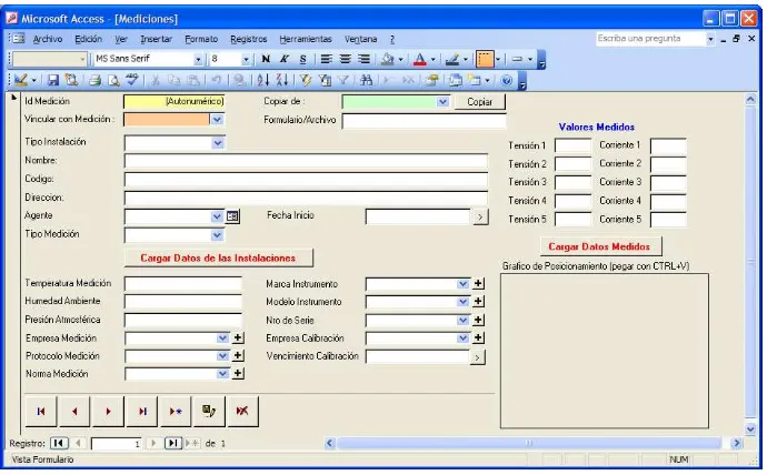
Measurements Table: to each registry corresponds an ID number (nº__Medicion). In this number it also stored general data of the facility (facility type, name, code, address, agent, etc.), the type of measurement which correspond the registry (electric field, magnetic field), the instruments used and the weather conditions (date, temperature, and atmospheric pressure) and the current values of voltage and current in each three-phase line in the facility. These are showed in Fig. 2.
Figure 2: Measurements Table.
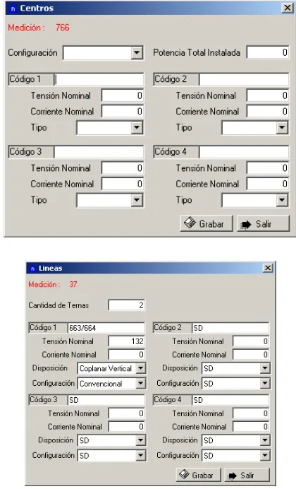
[image:3.595.140.485.490.704.2]Substation Table: It stores the typical facility data: substation type (HV/HV, HV/MV, MV/MV); the installed power capacity, which is the total sum of the transformers nominal powers (in MVA); the existence of only underground cables, only overhead lines or the presence of both. For each link corresponding to a HV level, it is indicated the code of the nominal voltage (in kV), the nominal current (in A) and the number of links with the same characteristics.
Distribution Transformation Table: it stores the data regarding this type of facility. It indicates if the transformation center is “At level”, “Aerial” or “Underground”. The total power installed it is indicated as the sum of the transformers nominal power (in kVA). Then the linking characteristics are loaded where each one of them is detailed with the code of the type: “power line” or “underground cable”, the nominal voltage (in kV) and the nominal current (in A).
Power Line Table: in this table, it is stored the number of three-phase lines, which could correspond to various independent three-phase lines or multiple three-phase lines (mounted over the same structure). It is indicated the code of each three-phase line (in case of a multiple three-phase line, in the same field there are displayed the corresponding codes for each three-phase line, separated by a dash). Then is indicated de disposition: “Coplanar Vertical”, “Coplanar Horizontal”, “Triangular” or “Preassembled”. When a disposition is “Coplanar Vertical” it is also indicated whereas the configuration is “Conventional” or “Linepost”. Then there are indicated the nominal voltage (in kV), nominal current (in A) in each three-phase line.
Underground Cables Table: for each cable is indicated the nominal voltage (in kV), the nominal current (in A) and the disposition “Coplanar” or “Equilaterally Spaced”.
[image:4.595.304.514.424.770.2]The different tables are presented in Fig.3
Value Table: in this table, there are stored the measured field values regarding the identified facility by the NºId__Medicion. The NºId__Medicion corresponds to a type of field measurement, which could be electric field or magnetic induction. For each facility there is a selection of sites, what it means is that certain points of the facility are chosen for the measurements. Each site is identified by a number, the distance to a reference point and when it is a power line, these distances are specified if it is to the right or to the left of the center of the power line. To each site it corresponds a measured value (or two in case the site requires a measurement to the right and another to the left). If the measurement corresponds to an electric field, it is loaded in kV/m and if it corresponds to a magnetic induction field it is loaded in uTesla. With this table comes a blueprint with the facility and the measurements sites.
2.3.Display of the Information
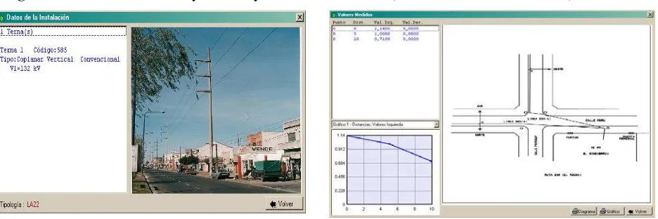
[image:5.595.68.536.283.439.2]For the display of the stored data, the application shows a window with different sections. It is possible view a window showing the facilities’ data, and photographs allowing to verify different topologies and the values of the EMF media, a chart with the resulting profile of the measurements, and the location of the spots where these were taken. See Figure 4.
Figure 4: Data from the surveyed facility and EMF measured (charts and sketches location)
Another possibility for the user is to search for measurements or select a group which match with one or several search criteria. This is achieved by the use of filters, which can be applied on any of the database
2.4.Facility classification
It is suggested to classify the facilities in four groups and inside each group define types and subtypes according to their characteristics: Substations (SE); Distribution Transformation MV/LV (CT); Underground Cable (CS) and Power lines (LA). The codes for each type and subtypes are the following:
Substations (SE).
SE2: Substation HV/MV
SE21: only overhead line SE22: linkage only underground SE23: air and ground links
SE3: Substation MV/MV
Distribution Transformation MV/LV (CT)
CT1: aerial
CT2: to level
CT3: underground
Underground Cable (CS)
CS1: underground cable HV (220 kV)
CS11: horizontal CS12: equilaterally spaced
unipolares tripolares
CS2: underground cable (132 kV to 66 kV)
CS21: horizontal CS22: equilaterally spaced
unipolares tripolares
CS3: underground cable MV (33 kV to 13.2 kV)
CS31: horizontal CS32: equilaterally spaced
unipolares tripolares
Power Lines (LA)
LA1: Power lines HV 220 kV and 500 kV
LA11: coplanar horizontal, single LA12conventional, single: coplanar vertical, LA13single : coplanar vertical, linepost,
LA14: coplanar vertical, several LA15: coplanar horizontal, several
LA2: Power lines: 132 kV and 66 kV LA21: coplanar horizontal,
conventional, single LA22
: coplanar vertical,
conventional, single LA23
LA24: triangular, conventional,
single
LA25: coplanar vertical,
conventional, several
LA26: coplanar vertical, linepost,
several
LA27: triangular, conventional, several
LA3: Power lines MV (33 kV and 13.2 kV)
LA31: coplanar horizontal,
conventional, single
LA321: coplanar vertical,
conventional, single
LA322: coplanar vertical,
linepost, single
LA331: triangular, conventional,
single
LA332: triangular, linepost,
single LA34: Preassembled
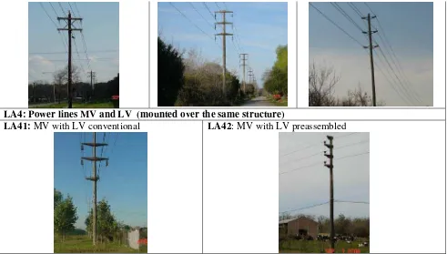
LA4: Power lines MV and LV (mounted over the same structure)
LA41: MV with LV conventional LA42: MV with LV preassembled
3. Measure verifications.
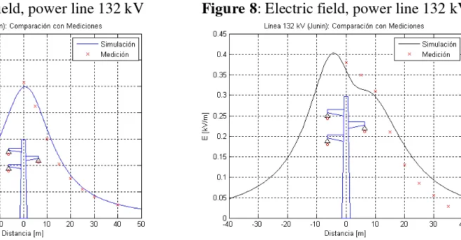
As an example, the electric and magnetic field profiles are presented, simulated and measured in power lines of 500kV and 132kV. The objective for that is to verify the measurements and simulation program.
[image:9.595.67.558.55.334.2]The results of simulation and records obtained in the measurements of the values of electric and magnetic field for a line at 500 kV, are presented in Fig. 5 and Fig. 6.
Figure 5: Magnetic field, power line 500 kV Figure 6: Electric field, power line 500 kV
Figure 7: Magnetic field, power line 132 kV Figure 8: Electric field, power line 132 kV
4. Final Comments
In order to make compatible the existing information in the ENRE resulting of different measurement campaigns of electric and magnetic fields generated by different facilities of the electrics companies, a database it has been elaborated and it has been saved in a systematized way the current available information. The database has been loaded with a total of 1102 registries, 537 of them are electric field measurements and the other 565 correspond to magnetic field. From the 1102 registries, 209 correspond to Substations, 699 Power Lines, 150 Distribution Centers and 44 Underground Cables. This database allows being upgraded with new registries from future measurements. Also it can be used to get information in a civilized way, for example classifying the results according the types of the facilities proposed.
It was verified through the calculation, the measurements made by the IITREE-LAT regarding the power lines. However it was not possible to reproduce the calculation values of the measurements made by other agents of the electric sector, due to the lack of constructive information of the facilities.
REFFERENCES
[1] MEDICIONES DE CAMPO ELÉCTRICO Y MAGNÉTICO EN INSTALACIONES DE 500 KV, Autores: D. A. Esteban, G. R. Camacho, R. Coloccia, Informe IT 575, Agosto 1996, IITREE-LAT-FI-UNLP.
[2] INSPECCIÓN Y MEDICIONES DE CAMPO ELÉCTRICO Y MAGNÉTICO, EN LÍNEAS DE 132 KV EN LA LOCALIDAD DE JUNÍN (PCIA. BS. AS.). Autores: R. Bianchi, D. Esteban y G. Barbera. Informe ENR 260, Diciembre 2000, IITREE-LAT-FI-UNLP.
[3] IEEE Std 644-1994, IEEE STANDARD PROCEDURES FOR MEASUREMENT OF POWER FREQUENCY ELECTRIC AND MAGNETIC FIELDS FORM AC POWER LINES, IEEE standard board.