Metrics for FIR Filters based on distributed arithmetic in FPGA
Martín Vázquez, Daniel Simonelli and Nelson AcostaINCA/INTIA – Facultad de Ciencias Exactas – UNICEN Paraje Arroyo Seco, Campus Universitario – Tandil, Argentina
{mvazquez|dsimonel|nacosta}@exa.unicen.edu.ar
ABSTRACT:In this paper, metrics regarding different architectures for distributed arithmetic based FIR filters in FPGA are presented. Main filter parameters are described as well as diverse design techniques applied: pipelining, bit-serial, digit-serial y bit-parallel. Each filter description was written in VHDL at RTL level. For achieving this goal no relative location (rloc) technique was used what redounds on more generic and expensive designs than those available through Core Generator tool. Implementation has been carried out over FPGAs belonging to Xilinx Virtex II family.
I. INTRODUCTION
Today's FPGAs high density has allowed a new field of application: single-chip systems design with embedded DSP algorithms [1,2]. Advantages of this solution are multiple: extra component usage is avoided, off-chip connections are reduced and DSP-core can be simplified and optimized with regard to the application, taking account of different aspects such as required data rate, precision, etc. Frequently bit-parallel circuits are used, but these implementations are expensive in terms of area yielding a greater speed than required. Digit-serial architectures are important choices for efficently implementing a wide range of circuits with real time signal processing. This solution allows the designer to get results expressed in terms of area-speed, ranging between both implementations: bit-serial and bit-parallel. [3]
Distributed arithmetic-based FIR filters are widely used for implementations that require high performance. Distributed arithmetic is basically a bit-serial operation that performs two vector product (one of which is constant). This technique avoids multiplications through the utilization of lookup tables (LUTs) taking highest advantage of technologies with plenty of memory elements such as RAM based FPGAs, where designers can use LUTs and adders to compute the product. [4] In this paper a comparison between different single-rate FIR filter architectures based on distributed arithmetic in FPGA is shown. With this aim, RTL descriptions in VHDL and automatic synthesis tools were used. This study involves bit-parallel, bit-serial, digit-serial and pipelining architectures. For descriptions, relative location (rloc) techniques [5] were not used and this allows generic designs to be implemented in any kind of FPGA although at a higher cost because the place and route is performed by the automatic synthesis tool at ease.
II. DISTRIBUTED ARITHMETIC
A FIR filter with T taps constant coefficients is characterized by:
T-1
y[n] =
Σ
h[n].x[n-k] k=0(1)
T-1
y = h’.x’ =
Σ
hi.xii=0
(2)
T-1 N -1
y =
Σ
hi.(-xi 0 +Σ
xi k.2-k)I=0 k=1
(3)
T-1 N -1 T-1
y = -
Σ
hi.xi 0+Σ
(
Σ
hi.xi k).2-k
i=0 k=1 i=0
(4)
N-1
y = -A0 (x0 0, x1 0,,,,xT-1 0) +
Σ
Ak(x0 k, x1 k,,,,xT-1 k).2-k
k=1
(5)
Where hi stands for known values conforming filter coefficients, T the number of taps, N input value precision and x the input data.
T-1
Ak (x0 k, x1 k,,,,xT-1 k) =
Σ
hi.xi ki=0
(6)
y = - (h0.x0 0 +h1.x 1 0 +...+hT-1.xT-1 0) + (h0.x0 1 +h1.x 1 0 +...+ hT-1.xT-11 ) 2-1 +
(h0.x0 1 +h1.x 1 1 +h2.x2 1 +...+ hT-1.xT-1 1 ) 2
-2
+ ... + (h0.x0 N-1 +h1.x 1 N-1 +...+hT.xT-1 N-1) 2
-(N-1)
(7)
Ak only can have a finite number of values (2T), what means that every single term in (7) is stored either in ROM or LUT. In fig. 1 is shown the way of implementing the sum of products where ROM size is 2TxWROM, with WROM the precision of output data.
Fig. 1 - Sum of products with distributed arithmetic
II. MODELS USED IN THIS WORK
[image:2.612.188.429.465.554.2]
Distributed arithmetic based filters have a bit-serial pattern (fig. 2). For N-bit precision inputs N clock cycles are need to yield an output, so that if CR is the clock rate, filter sampling rate (SR) is CR/N.
Fig. 2 – Bit-serial FIR filter
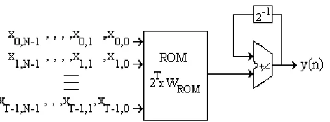
To indirectly increase the sampling rate, pipeline can be used. With this technique (pipelining) clock rate (CR) can be increased decreasing logical paths through the inclusion of registers. In fig. 3 is shown that the portion of segmented bit-serial architecture is that related with the cascaded adders that operate on the pre-stored values coming from ROMs or LUTs.
Fig. 3 – Pipelinedbit-serial FIR filter
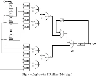
[image:3.612.151.464.139.308.2] [image:3.612.157.462.379.551.2]Fig. 4 – Digit-serial FIR filter (2-bit digit)
Let CR be the clock rate, SR the filter' sampling rate, N the input size, D the digit size, therefore the following assertions may be assumed as valid (theoretically):
SR[bit-serial] = CR [bit-serial]/N
SR[digit-serial] = DxSR [bit-serial] SR[parallel] = SR [digit-serial]
CR[bit-serial con pipelining] > CR[bit-serial] => SR[bit-serial with pipelining] > SR[bit-serial]
CR[digit-serial con pipelining] > CR[digit-serial] => SR[digit-serial with pipelining] > SR[digit-serial] When FPGAs are used, it is not possible to certify these assertions because the implementation strongly depends on the successive stages of the automatic synthesis process [7]. As a matter of fact, in this experience neither relative location (rloc) technique nor physical or logical constraints were used. Therefore the place and route tool proceeded at ease when performing physical design for the different alternatives.
III. EXPERIMENTAL RESULTS
[image:4.612.125.492.94.385.2]
• FIR bit-serial
• FIR bit-serial with pipelining • FIR digit-serial (digit size 2)
• FIR digit-serial (digit size 2) with pipelining • FIR digit-serial (digit size 4)
• FIR digit-serial (digit size 4) with pipelining • FIR bit-parallel
Taps B-Serial B-Serial Pipe
D-Serial (2) D-Serial (2) Pipe
D-Serial (4) D-Serial (4) Pipe
B-Parallel
8 101,94 149,48 85,32 133,69 62,03 73,26 43,63
12 92,25 144,30 73,21 123,91 54,79 81,57 36,79
16 80,71 138,12 68,68 112,99 51,02 70,97 32,16
24 73,69 142,04 63,01 117,92 40,75 77,34 30,07
32 69,98 131,93 55,01 106,72 39,81 71,17 29,58
[image:5.612.110.498.217.309.2]64 53,05 92,51 46,30 90,01 36,35 63,86 29,88
Table 1 – Clock rate (CR) for filters with 8-bit inputs and coefficients [Mhz]
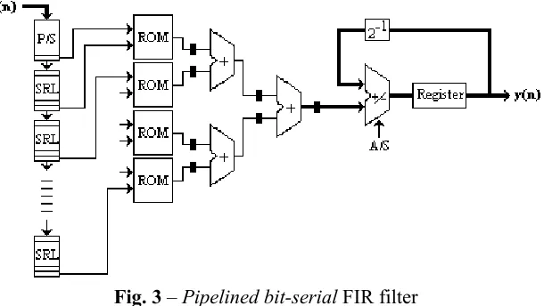
Table 1 shows that bit-serial filters with pipelining have the best CR for 8-bit inputs and coefficients but this is not what happened with the sampling rate (SR) because of the different digit sizes involved. In table 2 can be seen that, best SR filters (for all tap numbers, except for 8) were those implemented as digit-serial with pipelining and digit size equal 4.
Taps B-Serial B-Serial Pipe
D-Serial (2) D-Serial (2) Pipe
D-Serial (4) D-Serial (4) Pipe
B-Parallel
8 12,74 18,68 21,33 33,42 31,01 36,63 43,63
12 11,53 18,04 18,30 30,98 27,39 40,78 36,79
16 10,09 17,26 17,17 28,25 25,51 35,48 32,16
24 9,21 17,75 15,75 29,48 20,37 38,67 30,07
32 8,74 16,49 13,75 26,68 19,90 35,58 29,58
[image:5.612.112.503.386.476.2]64 6,63 11,56 11,57 22,50 18,17 31,93 29,88
Table 2 – Sampling rate (SR) for filters with 8-bit inputs and coefficients [Mhz]
Tables 3 and 4 show slices and equivalent gates occupation for the 8-bit input filters. As expected, parallel filters are those more expensive in terms of slices and equivalent gate occupation.
Taps B-Serial B-Serial
Pipe
D-Serial (2) D-Serial (2) Pipe
D-Serial (4) D-Serial (4) Pipe
B-Parallel
8 63 (1) 72 (1) 80 (1) 85 (1) 117 (1) 120 (1) 178 (1)
[image:5.612.109.501.538.628.2]12 92 (1) 106 (1) 120 (1) 135 (1) 184 (1) 201 (1) 298 (2) 16 122 (1) 135 (1) 161 (1) 174 (1) 244 (2) 261 (2) 395 (3) 24 188 (1) 209 (1) 259 (2) 287 (2) 408 (3) 447 (4) 680 (6) 32 239 (2) 252 (2) 324 (3) 335 (3) 494 (4) 506 (4) 825 (7) 64 477 (4) 508 (4) 660 (6) 699 (6) 1030 (9) 1089 (10) 1718 (15)
Taps B-Serial B-Serial Pipe
D-Serial (2) D-Serial (2) Pipe
D-Serial (4) D-Serial (4) Pipe
B-Parallel
8 1296 1660 1574 2014 2178 3124 3156
12 1860 2512 2372 3470 3486 5518 5426
16 2338 3028 2988 4156 4336 6544 6700
24 3536 4832 4736 7108 7244 11774 11720
32 4448 5830 5890 8434 8822 13756 14056
[image:6.612.112.500.94.183.2]64 8706 11508 11786 17156 18006 28572 29234
Table 4 – Equivalent gate occupation for FIR with 8-bit inputs and coefficients
The following 12-bit inputs and coefficients filters were designed and implemented:
• FIR bit-serial
• FIR bit-serial with pipelining • FIR digit-serial (digit size 2)
• FIR digit-serial (digit size 2) with pipelining • FIR digit-serial (digit size 4)
• FIR digit-serial (digit size 4) with pipelining • FIR digit-serial (digit size 6)
• FIR digit-serial (digit size 6) with pipelining • FIR bit-parallel
Table 5 shows that bit-serial filters with pipelining have the best CR for 12-bit inputs and coefficients (as happened with 8-bit precision). Regarding the sampling rate (SR), in table 6 can be seen that, best SR filters were those implemented as digit-serial with pipelining and digit size equal 6.
Taps B-Serial B-Serial
Pipe D-Serial (2) D-Serial (2) Pipe D-Serial (4) D-Serial (4) Pipe D-Serial (6) D-Serial (6) Pipe B-Parallel
8 111,60 133,15 75,07 131,93 61,05 70,67 44,31 53,30 25,99
12 92,98 131,06 73,80 122,10 53,99 75,81 40,92 51,33 25,32
16 85,11 129,03 69,83 115,07 51,39 74,40 38,94 50,45 24,08
24 63,86 129,87 59,84 118,48 43,76 71,63 34,47 49,07 21,89
32 64,68 122,25 48,68 110,99 43,29 72,41 31,54 48,17 21,71
64 47,71 100,20 43,94 94,61 34,78 57,50 29,66 46,32 20,25
Table 5 – Clock rate (CR) for filters with 12-bit inputs and coefficients [Mhz]
Taps B-Serial B-Serial
Pipe D-Serial (2) D-Serial (2) Pipe D-Serial (4) D-Serial (4) Pipe D-Serial (6) D-Serial (6) Pipe B-Parallel
8 9,30 11,09 12,51 21,99 20,35 23,56 22,15 26,65 25,99
12 7,75 10,92 12,30 20,35 17,99 25,27 20,46 25,66 25,32
16 7,09 10,75 11,64 19,18 17,13 24,80 19,47 25,22 24,08
24 5,32 10,82 9,97 19,75 14,59 23,88 17,23 24,53 21,89
32 5,39 10,19 8,11 18,50 14,43 24,14 15,77 24,08 21,71
[image:6.612.93.519.424.645.2]64 3,97 8,35 7,32 15,77 11,59 19,17 14,83 23,16 20,25
Table 6 – Sampling rate (SR) for filters with 12-bit inputs and coefficients [Mhz]
Taps B-Serial B-Serial Pipe D-Serial (2) D-Serial (2) Pipe D-Serial (4) D-Serial (4) Pipe D-Serial (6) D-Serial (6) Pipe B-Parallel
[image:7.612.89.529.93.191.2]8 91 (1) 102 (1) 115 (1) 121 (1) 167 (1) 171 (1) 221 (2) 224 (2) 368 (3) 12 133 (1) 150 (1) 173 (1) 191 (1) 261 (2) 286 (2) 345 (3) 380 (3) 589 (5) 16 174 (1) 189 (1) 229 (2) 242 (2) 344 (3) 362 (3) 459 (4) 481 (4) 793 (7) 24 266 (2) 293 (2) 357 (3) 396 (3) 561 (5) 616 (5) 761 (7) 837 (7) 1328 (12) 32 339 (3) 355 (3) 454 (4) 466 (4) 689 (6) 704 (6) 927 (8) 940 (8) 1617 (15) 64 668 (6) 706 (6) 910 (8) 957 (8) 1398 (13) 1476 (13) 1887 (17) 1918 (18) 3309 (30)
Table 7 – slices occupation for FIR with 12-bit inputs and coefficients (Percentage over a total of 10752 slices)
Taps B-Serial B-Serial
Pipe D-Serial (2) D-Serial (2) Pipe D-Serial (4) D-Serial (4) Pipe D-Serial (6) D-Serial (6) Pipe B-Parallel
8 1840 2356 2246 2996 3130 4474 4044 6010 6420
12 2628 3524 3364 4866 4938 7754 6522 10680 10930
16 3282 4252 4204 5848 6120 9244 8052 12678 13456
24 4956 6744 6606 9908 10090 16440 13570 23004 23506
32 6192 8116 8194 11726 12270 19150 16362 26612 28008 64 11998 15850 16168 23542 24592 39124 33002 54744 57074
Table 8 – Equivalent gate occupation for FIR with 12-bit inputs and coefficients
Let δ be the relationship between the sampling rate (throughput) and the area or number of equivalent gates. This quantity was computed for every single filter(i,j), where i stands for the coefficient number or taps (row of tables) and j stands for the technique applied (column of tables). Hence:
δ [filter(i,j)] = [SR(i,j) / EG(i,j) ]* r(i) (8)
where EG is the equivalent gate number for the design and r(i) a factor used for normalizing SR(i,j) as well as EG(i,j):
r(i) = max[EG (i,j)] / max[SR(i,j)] (9)
maximums are computed for all j or filters designed for a certain tap (i row).
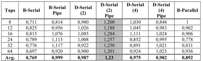
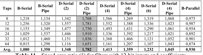
Tables 10 and 11 show speed (rate)-area ratio for filters with 8-bit and 12-bit inputs respectively. Values were computed through (8)
Taps B-Serial B-Serial
Pipe D-Serial (2) D-Serial (2) Pipe D-Serial (4) D-Serial (4) Pipe B-Parallel
8 0,711 0,814 0,980 1,200 1,030 0,848 1
12 0,825 0,956 1,026 1,188 1,045 0,983 0,902
16 0,815 1,076 1,085 1,284 1,111 1,024 0,906
24 0,789 1,113 1,008 1,257 0,852 0,995 0,778
32 0,776 1,117 0,922 1,250 0,891 1,021 0,831
64 0,697 0,920 0,900 1,201 0,924 1,023 0,936
Avg. 0,769 0,999 0,987 1,23 0,975 0,982 0,892
[image:7.612.131.483.561.668.2]Taps B-Serial B-Serial Pipe
D-Serial (2)
D-Serial (2) Pipe
D-Serial (4)
D-Serial (4) Pipe
D-Serial (6)
D-Serial (4) Pipe
B-Parallel
8 1,218 1,134 1,342 1,768 1,566 1,269 1,319 1,068 0,975
12 1,256 1,320 1,557 1,781 1,552 1,388 1,336 1,023 0,987
16 1,153 1,349 1,477 1,750 1,493 1,431 1,290 1,061 0,954
24 1,029 1,537 1,446 1,910 1,336 1,392 1,217 1,021 0,892
32 1,012 1,460 1,151 1,836 1,368 1,466 1,121 1,052 0,901
64 0,815 1,298 1,116 1,651 1,161 1,207 1,107 1,043 0,874
[image:8.612.103.513.92.203.2]Avg. 1,080 1,350 1,348 1,782 1,413 1,359 1,232 1,045 0,930
Table 11 – Speed-area ratio (δ) for filters with 12-bit inputs and coefficients
IV. CONCLUSIONS
A distributed arithmetic based single-rate FIR in FPGAs study was presented. 8-bit and 12-bit inputs and coefficients filters were analyzed as well as a wide coefficient diversity.
As no relative location (rloc) technique was used, designs are generic, i.e. can be implemented over any FPGA.
Although the synthesis tool had the maximum freedom degree for implementing at ease, results obtained have a close correspondence with that expected through theoretically considerations. Bit-parallel filters are more expensive in terms of area but are faster (in terms of sample rate) than digit-serial filters, which in turn are more expensive and faster than bit-serial filters. Through the application of pipelining techniques speed and area were increased.
Finally, was concluded that digit-serial with pipelining and digit size 2 implementation has the best speed-area ratio (δ) among all filters considered in this work.
V. REFERENCES
1. G. Spivey, S. Bhattacharyya, K. Nakajima, "Logic Foundry: Rapid Prototyping for FPGA-Based DSP Systems". EURASIP Journal on Applied Signal Processing 2003, pp 565-579. Hindawi Publishing Corporation, 2003
2. Mentor Graphics, "FPGAs: Fast Track to DSP". White Papers.
www.techonline.com/community/tech_group/dsp/tech_paper. January 2003.
3. J. Valls, M. Martinez-Peiro, T. Sansaloni, and E. Boemo, "Design and FPGA Implementation of Digit-Serial FIR Filters", Vol.2, pp.191-194, Lisboa, 7-10 Sept. 1998.
4. S. Hwang, G. Han, S. Kang, J. Kim, "New Distributed Arithmetic Algorithm for Low-Power FIR Filter Implementation". IEEE Signal Processing Letters, Vol. 11, No 5, pp 463-466. May 2004 5. Xilinx, inc. "Constraints Guide - ISE5.1" section 2-4, 2-15 "Relative Location (RLOC) and
Relationally Placed Macros (RPMs)", 2002.
6. F.E. Angarita, M.J. Canet, J. Valls, F. Viñedo, "Implementación de un core IP: Filtro basado en aritmética distribuida". III Jornadas de Computación Reconfigurables y Aplicaciones (Computación reconfigurable & FPGAs), pp. 139-145. Madrid, September 2003.
7. D. Simonelli and M. Vázquez, "Metrics for Fast, Low-Cost Adders in FPGA". CACIC 2003. La Plata, Argentina. September 2003. Pp. 1384-1392.
8. Xilinx, inc. "Xilinx Synthesis Technology (XST) User Guide", 2002, available at www.xilinx.com.
![Table 2 – Sampling rate (SR) for filters with 8-bit inputs and coefficients [Mhz]](https://thumb-us.123doks.com/thumbv2/123dok_es/4758750.60993/5.612.112.503.386.476/table-sampling-rate-sr-filters-inputs-coefficients-mhz.webp)
![Table 6 – Sampling rate (SR) for filters with 12-bit inputs and coefficients [Mhz]](https://thumb-us.123doks.com/thumbv2/123dok_es/4758750.60993/6.612.93.519.424.645/table-sampling-rate-sr-filters-inputs-coefficients-mhz.webp)