UNIVERSIDADE DA CORUÑA
ESCOLA POLITÉCNICA SUPERIOR
A Collaborative Environment
for
Flexible Development of MBS Software
A thesis submitted for the degree of
Doctor Ingeniero Industrial
Manuel Jesús González Castro
Ingeniero Industrial
Advisor: Javier Cuadrado Aranda
To my family:
Pura, Manolo, Rodrigo and Chus.
I
Acknowledgements
This Ph.D. thesis has been conducted at the Mechanical Engineering Laboratory of University of A Coruña, headed by Prof. Javier Cuadrado. The dissertation fits into the research projects A unified simulation environment for real-time multibodv systems dynamics with stress analysis and control (2001 2003), and Collaborative tools for multibody system dynamics (2004-2006),
both of them supported by the Spanish Ministry of Science and Technology. First, I wish to express my special gratitude to Prof. Javier Cuadrado, my advisor. He encouraged me to start my academic career five years ago and, since then, he has provided an excellent advice and support in this work and in all aspects of teaching and research.
My colleagues at the Mechanical Engineering Laboratory provided an excellent work environment. I spent many enjoyable hours with them. Many thanks to Ruth Gutiérrez, Paz Morer, Miguel Angel Naya, Daniel Dopico and Urbano Lugrís. Some of our undergraduate students collaborated in this project: wish to thank Carolina Fidalgo, Todor Minakov, Cristina Vizoso, and especially, Cristóbal Piñón.
During my doctorate, I have made a couple of stays at other universities. The first one was at Universidad Politécnica de Madrid, under the supervision of Prof. Javier García de Jalón. I wish to thank him and his students for the very productive and enthusiastic discussions about XML. The second stay was at University of Illinois at Chicago, supervised by Pro£ Ahmed A. Shabana. I am grateful to him for providing me such a great opportunity. I wish to express my gratitude to the students and researchers at his laboratory, for welcoming me so warmly. One of the persons I met there, José Luis Escalona, deserves special thanks for his hospitality and for introducing me into the fascinating world of rail vehicle dynamics.
Last but not least, many thanks to my family for their love and support: my parents Pura and Manolo, my brother Rodrigo and my girlfriend Chus.
Agradecimientos
Esta tesis doctoral ha sido realizada en el Laboratorio de Ingeniería Mecánica de la Universidad de A Coruña, dirigido por el profesor Javier Cuadrado. La tesis se enmarca en los proyectos de investigación Un entorno unificado de .simulación para la dinámica en tiempo real de si.stemas multicuerpo con
análisis tensional y control (2000-2003), y Herramientas de colaboración en
dinámica de sistemas multicuerpo (2004-2006), ambos financiados por el
Ministerio de Ciencia y Tecnología de España.
En primer lugar, me gustaría dar las gracias al profesor Javier Cuadrado, mi director de tesis. Él fue quien me animó a iniciar mi carrera docente e investigadora hace ya cinco años, y desde entonces me ha guiado y apoyado en este trabajo y en todos los aspectos de mi actividad académica.
Mis compañeros del Laboratorio de Ingeniería Mecánica han proporcionado un excelente entorno de trabajo. Con ellos he pasado muchas horas agradables. Muchas gracias a Ruth Gutiérrez, Paz Morer, Miguel Angel Naya, Daniel Dopico y Urbano Lugrís. Algunos de nuestros estudiantes de ingeniería han colaborado en este proyecto: quiero dar las gracias a Carolina Fidalgo, Todor Minakov, Cristina Vizoso y, de manera especial, a Cristóbal Piñón.
Durante mi doctorado he realizado dos estancias en otras universidades. La primera, en la Universidad Politécnica de Madrid, con el Professor Javier García de Jalón. Quiero darle las gracias a él y a sus estudiantes por las apasionantes y productivas discusiones que mantuvimos acerca del XML. La segunda estancia tuvo lugar en la University of Illinois at Chicago, con el profesor Ahmed A. Shabana. Le estoy muy agradecido por proporcionarme una oportunidad tan extraordinaria. Quiero dar las gracias a los estudiantes e investigadores de su laboratorio, por proporcionarme una cálida acogida. José Luis Escalona, con quien trabajé en Chicago, merece un agradecimiento especial por su hospitalidad y por introducirme en el apasionante mundo de la dinámica de ferrocarriles.
Por último, muchas gracias a mi familia por su cariño y apoyo: mis padres Pura y Manolo, mi hermano Rodrigo y mi novia Chus.
Abstract
Currently, research in multibody systems (MBS) dynamics lacks appropriate tools to support collaboration between different research teams. This thesis addresses that problem, making three contributions to streamline the development of MBS simulation software in a collaborative and flexible way:
First, a study of the interoperability status in multibody systems simulation software is presented. Existing information modeling techniques have been evaluated as candidates to develop a neutral data format for MBS simulation, and a prototype of an XML-based data format have been proposed. Benefits and limitations of this new format are highlighted.
Second, a benchmark for MBS dynamics has been developed. The benchmark includes a collection of test problems and a procedure to measure the performance of a given simulator. In addition, a web-based management system for benchmarking results has been implemented, and the commercial software ADAMS has been tested with the proposed benchmark.
Third, a C++ prototype implementation of a modular and extensible MBS simulation software tool is proposed. Several Open Source development environments and Computer Aided Software Engineering (CASE) tools have been evaluated in the context of the development of such a library.
The three components toghether allow sharing systems models, simulation results and software implementations, and made up the basis for a collaborative environment for the flexible development of MBS simulation software.
Resumen
La investigación en dinámica de sistemas multicuerpo (MultiBodv Svstems, MBS) carece de herramientas que permitan la colaboración entre distintos
grupos de investigación. Esta tesis hace tres contribuciones en este sentido, con el fin de facilitar el desarrollo de software de simulación de sistemas multicuerpo, de forma colaborativa y flexible:
En primer lugar, se ha realizado un estudio sobre el grado de interoperabilidad existente en el software de simulación de MBS. Se han evaluado las técnicas de modelado de información existentes que son susceptibles de ser empleadas para desarrollar un formato de datos para la simulación de MBS, y se ha definido un prototipo de formato de datos basado en el lenguaje XML.
En segundo lugar, se ha desarrollado un benchmark para dinámica de MBS. El benchmark incluye una colección de problemas y define un procedimiento para medir el rendimiento de un determinado simulador. Además, se ha implementado una aplicación web para la gestión de resultados del benchmark, y se han medido las prestaciones del software comercial ADAMS utilizando el benchmark propuesto.
En tercer lugar, se ha propuesto un prototipo de software modular y extensible para la simulación de MBS, programado en lenguaje C++. Para ello, se han evaluado diferentes entornos de desarrollo Open Source y herramientas de diseño de software asistido por ordenador.
La combinación de los tres componentes permite compartir modelos de sistemas, resultados de simulaciones e implementaciones de software, constituyendo la base de un entorno colaborativo para el desarrollo flexible de software de simulación de sistemas multicuerpo.
Content
CHAPTER 1. INTRODUCTION ...1
1.1 MULTIBODY SYSTEM DYNAMICS ... I 1.2 MOTIVATION ...3
1.3 $COPE AND OBJECTIVES ...6
1.4 ^RGANIZATION ...7
1.S REFERENCES ... ...8
CHAPTER 2. NEUTRAL DATA MODELS FOR MBS SIMULATION ...9
2.1 INTRODUCTION ...9
2.2 STATE OF THE ART ...13
2.2.1 Information modeling ...14
2.2? Neutral data jormats for engineering product data ...?0
2.2.3 Data formats in MBS software ... 23
2.2.4 Other data jormats of interest ... 27
2.2.5 Summarv ...27
2.3 REQUIREMENTS FOR A NEUTRAL MBS DATA FORMAT ...28
2.3.1 Foster data reutilization ...28
2.3.2 Foster data exchanging and sharing ...29
2.3.3 Streamline the acceptance into the research communitv ...30
2.4 EVALUATION OF COMMERCIAL MBS SOFTWARE ...32
2.4.1 Software selected for the evaluation ...32
2.4.2 Evaluation criteria ... 33
2.4.3 Summarv ...39
2.S TI-IE STEP sTANDARD ...40
2.5.1 Architecture ...40
2.5.2 Modeling language ...44
2. 5. 3 I mp l em en ta ti on . . . . .. . . .. . . .. . . 4 S 2. S.4 Supporting tools ... 46
2.5.5 Applications ...47
2.6 THE XML DATA FORMAT ...47
2. 6.1 Imp 1 em en ta ti on . . . .. . . .. . . .. . . .. . 4 7 2.6.2 Modeling language ...48
2. 6.3 Supporting tools ... SI 2.6.4 Applications ...52
2.7 EVALUATION OF STEP AND XML ...53
2. 7. I Model design ... S3 2.7. 2 Model implementation ...56
2.7.3 Summan^ ...60
2.8 PROTOTYPE IMPLEMENTATION OF AN XML-BASED DATA MODEL ...63
?.8.1 Overall model design ... 63
2.8.2 Schema model ...70
2.8.3 Application program interface ...76
2.8.4 Support for data reuse. share and exchange ... 79
?.8.5 Summart^ ...81
2.9 PROTOTYPE IMPLEMENTATION OF AN XML PREPROCESSOR ...82
2.10 COtiCLUSIONS AND FUTURE R'ORK ...85
2.11 REFEREVCES ...87
CHAPTER 3. BENCHMARKING OF MBS SIMULATION CODES ...97
3.1 INTRODUCTION ...97
3.2 STATE OF THE ART ... 100
3.2.1 Benchmarking of MBS simulation codes ...100
3.2.2 Benchmarking of other simulation tools in Mechanical Engineering ...104
3.2.3 Benchmarking of ODE/DAE solvers ... lOS 3.2.4 Benchmarking of computing systems ...107
3.2.5 Summary ...109
3.3 FACTORS INFLUENCING SIMULATION PERFORMANCE ... 1 10 3.3.1 Problem ...110
3.3.2 Formalism ...111
3.3.3 Implementation ...112
3. 3.4 Computer ...113
3.4 PROPOSED BENCHMARK ... 116
3.4.1 Prohlem set ...116
3.4.2 Reference solutions ...125
3.4.3 Perĵormance measurement ...132
3.4.4 Documentation ...138
3.$ MANAGEMENT OF BENCHMARK RESULTS ... 1 S2 3. S.1 Results database ...1 S4 3.5.2 Results submission ...1 S6 3.5.3 Results retrieval and comparison ...156
3.6 APPLICATION TO ADAMS ... ... 160
3.6.1 Formulation and integrator comparison ...162
3.6.Z Solver version comparison ...165
3.6.3 Solver language comparison ...167
3.6.4 Hardware comparison ...168
3.7 CONCLUSIONS AND FUTURE WORK ... 171
3.8 REFERENCES ... 173
CHAPTER 4. AN OPEN MBS SIMULATION SUITE ...183
4.1 INTRODUCTION ... 1 ó3 4.2 OPEN SOURCE SOFTWARE ... 186
4.2. ] Characteristics ...186
4.?.2 Open source MBS software ... 188
4.Z.3 Open source libraries for MBS software ...189
4.?.4 Summarv ...19?
4.3 SOFTWARE ENGINEERING TOOLS AND METHODOLOGIES ... 193
4.3.1 Programming lunguages ...193
4.3.Z Softx^are processes ...193
4.3.3 Computer aided softx^are engineering tools ...194
4.4 CONCURRENT DEVELOPMENT TOOLS ... 197
4.4. I Open source project hosts ...197
4.$ PROTOTYPE OF AN OPEN SOURCE MBS LIBRARY ... 199
4.5.1 Development environment ...199
4.5.2 Overall design ... Z00 4.6 CONCLUSIONS AND FUTURE WORK ... 202
4.7 REFERENCES ... 203
CHAPTER 5. CONCLUSIONS ...207
5.1 CONCLCJSIONS ...207 5.2 Fu^ru^ wo^c ...208
Chapter 1.
Introduction
1.1 Multibody system dynamics
The principles of classical mechanics were established by Newton [ 1], Euler [2] and Lagrange [3] more than two hundred years ago. However, until the end of the 20th century, the process of analyzing systems of rigid bodies undergoing overall motions involving large amplitude rotations remained an intimidating task. First, one had to develop an idealized mathematical model of the real system. Then, one was faced with the difficult chore of manually formulating the equations governing the behavior of the model. This typically involved a considerable amount of algebraic manipulations, was prone to mistakes, and was virtually impossible to accomplish for any system having more than just a few degrees of freedom. Finally, if an analyst was skilled enough to complete the first two tasks, the obstacle of finding a closed-form solution of the equations was difficult enough to restrict the entire process to only the most skilled scientists addressing the very simplest mechanical systems.
2 Chapter 1. Introduction
techniques to harness the power of computers to formulate and solve equations governing large overall motions of complex rigid and flexible systems. Various computational methods and computer formalisms for mathematical modeling and simulation of complex multibody systems have been developed over the past three decades; excellent reviews of past and recent developments by Schiehlen [4] and Shabana [5] were published in 1997.
In recent years, MBS technology evolved in powerful computer analysis software, which became a valuable tool in industry and research areas, complementing the Finite Element Method for the simulation of systems undergoing large displacements in space. Such tools make possible to evaluate serviceability, robustness and behavior of a product design in all the situations that it will encounter during its life, prior to building a prototype. Its application reduces product development costs, allows the evaluation of more alternative designs, and shortens the time it takes to bring a new product to the market place. MBS dynamics has diverse applications in automotive (cars, light trucks, heavy trucks and off-road vehicles, railway), aerospace (airplanes, spacecrafts, defense, satellites), general machinery (manufacturing and assembly equipment) or electro-mechanical product industries (copy machines, magnetic and optical storage devices, laser and inkjet printers, etc.), among many others.
Although multibody system dynamics is already a powerful and robust technique, and general purpose MBS software is ready available for production use, it has not reached a mature state yet [4]. The cutting edge research in this field is currently aiming towards developing new facilities related, on one hand, to include into the analytical formalisms the complex non-linear aspects like stick-slip friction, flexibility, contact and impact problems, extension to electronic and mechatronic systems, optimal system design, strength analysis and interaction with fluids, etc., and, on the other hand, to increase the computing speed in order to enable real-time simulation of complex systems.
3 1.2. Motivation
very narrow conjunctions, leading to the field which is now universally referred to as many-body systems. There are many problems in biomechanics that are currently modeled and solved by multibody dynamics. The applications are ranging from vehicle occupants to sport sciences and prosthetics. Multibody dynamics is also a solid basis for non-linear dynamics. In particular, impact and friction induced vibrations show chaotic behavior. The noise generation in railway wheels due to rail-wheel contact forces can also be considered as a highly non-linear phenomenon. An up-to-date development includes also the control of chaos. The control aspects in multibody dynamics are becoming more important. Vehicle, aircraft and spaceship dynamics and reliability have always been challenging applications. In relation with the transportation systems, a contemporary application of multibody dynamics is the structural and occupant crashworthiness.
In conclusion, multibody system dynamics is a very lively and promising research subject: many interesting and complex issues remain to be solved, and its range of applications is growing constantly.
1.2 Motivation
4 Chapter 1. Introduction
New
method
Implement
* Software
1
Challenging MBS system
problems
no
Measure
^ Performance
metrics
Compare with existing methods
_^ ^, t
Publish
Figure 1.1: Steps followed in multibody systems research.
1.2. Motivation S
industrial applications, but many others do not have these facilities and can only implement, after many hours of work, a proof of concept of their ideas. In addition, the proliferation of different in-house developed tools, with different data formats and interfaces, causes important interoperability problems when several teams try to collaborate.
Research in the MBS field lacks the tools and methodologies to support collaboration, and collaboration is essential in today's world: applications of mechanical engineering (and, in particular, applications of MBS dynamics) have reached such a level of complexity that they require the participation of several research teams, so that each of them can provide knowledge and expertise in a particular aspect. Furthermore, today's knowledge-based societies are heavily dependent on their capacity to produce, transfer and utilize knowledge. This requires mobilizing cognitive resources, beginning with the research community.
Governments realized soon about the importance of collaboration in research and the need to develop interoperable tools and technologies. For example, The European Commission has been supporting these developments through its various research programs since the early 1980s, and one of its instruments, Networks of Excellence [6], is specially aimed at integrating scattered groups
related to a particular research topic into virtual organization.s, which share and develop common research equipment, tools and platforms, and work together as a single team using Information and Communication Technologies. These virtual organizations of researchers create synergies among the participants and avoid parallel or redundant development efforts. As a result, the productivity of the participants is increased and research and technological development in that field is accelerated [7].
6 Chapter 1. Introduction
1.3 Scope and objectives
The first step to set up an environment that supports the collaboration among different MBS research groups is to develop tools and standards that support this collaboration. Since most of the research resources are spent in modeling multibody systems and in implementing and testing new simulation methods, the tools should be designed to streamline such tasks. Particularly, three priorities have been identified:
• Share multibody systems model.s. The lack of a standard data format to
encode information about MBS models hinders the exchange and share of models between users of MBS software. The current interoperability status between MBS simulation tools should be evaluated, and available technologies should be explored in order to develop a robust yet easy-to-use neutral data format for multibody systems.
• Share performance metrics of simulation methods. Currently, benchmarking
of MBS simulation tools is done on an individual basis: different authors use different sets of problems to evaluate performance, and the procedures and conditions considered to measure computational efficiency are also different. Benchmarking in this field should be standardized, and performance metrics obtained by different teams for different simulation methods should be collected, managed and published in a collaborative, centralized platform, so that they can be accessed and monitored by all interested partners.
• Share implementations of simulation method.s. The implementation of
simulation methods is one of the most time-consuming tasks in MBS research. In addition, resulting implementations are hardly shared among groups, since they often use very different programming environments and techniques. An open, modular and extensible simulation software would help to integrate small contributions from different research teams, in order to build up a robust and comprehensive simulation suite. Collaborative development environments shall be used to accomplish this task.
7 1. 4. Organization
1.4 Organization
This thesis is organized as follows:
• Chapter 1: Introduction.
• Chapter 2: Neutral data models for MBS simulation. • Chapter 3: Benchmarking of MBS simulation codes. • Chapter 4: An open MBS simulation suite.
• Chapter 5: Conclusions and future work.
Chapter 1 provides a brief historical review of multibody systems analysis, and presents the motivation, scope and objectives of this work.
Chapter 2 presents a review of the standardization efforts in the field of engineering product data and, in particular, multibody systems data. Two popular technologies for building data models, STEP and XML, are evaluated and compared. Finally, a prototype implementation of an XML-based neutral data format for multibody systems simulation is presented.
Chapter 3 presents a review of the benchmarking activities developed in MBS dynamic simulation and other related fields, showing that performance benchmarking is not a standardized practice in this field. Factors that contribute to the computational efficiency of a MBS dynamic simulator are identified and described, and a benchmarking suite for multibody system simulation software is proposed. The suite includes a web-based application to collect, manage and publish benchmarking results.
Chapter 4 reviews existing technologies that facilitate the collaborative development of software products, like Open Source environments and Computer Aided Software Engineering (CASE) tools, and presents a C++ prototype implementation of a modular and extensible MBS simulation software tool.
8 Chapter 1. Introduction
1.5 References
[1] Newton, I., 1687, Philosophiae Naturalis Principia Mathematica, Royal Society, London.
[2] Euler, L., 1776, "Nova Methods Motum Corporum Rigidarum
Determinandi," Novi Commentarii Academiae Scientiarum Petropolitanae, 20, pp. 208-238.
[3] Lagrange, J. L., 1788, Mécanique Analytique, L'Académie Royal des Sciences, Paris.
[4] Schiehlen, W., 1997, "Multibody System Dynamics: Roots and Perspectives," Multibody System Dynamics, 1(2), pp. 149-188.
[5] Shabana, A. A., 1997, "Flexible Multibody Dynamics: Review of Past and Recent Developments," Multibody System Dynamics, 1(2), pp. 189-222.
[6] European Commision, 2003, "Networks of Excellence," http://europa.eu.int/comm/research/fp6/instruments en.html.
Chapter 2.
Neutral data models for MBS
simulation
2.1 Introduction
Over the past two decades there has been an enormous shift in product development caused by the advent of two factors. The first one is the availability of computer-aided design, engineering and manufacturing (CAD/CAE/CAM) tools, considered one of the best engineering achievements of the 20`^ century; the introduction of these tools represented tremendous productivity gains compared to the methods used before. The second factor is the emergence of low-cost communications and information technologies, which allow engineering organizations to interoperate with each other at large scale: companies form joint ventures to address business opportunities and work globally within multi-company consortia to perform design, analysis and manufacturing activities. Therefore, in today's world engineering products are often developed by geographically and temporally distributed design teams using heterogeneous CAx software [1]. This heterogeneity of engineering software exists even in single companies, since most of them find it difficult to enforce the use of a common set of CAD/CAE/CAM tools within the ĵ
organization.
10 Chapter 2. Neutral data models for MBS simulation
poor interoperability between CAD/CAE/CAM systems. A study performed in 1999 by the National Institute of Standards and Technology (NIST) estimated that the economic cost due to the lack of interoperability in the United States automotive supply chain alone at one billion dollars per year [2]. The estimated cost in shipbuilding, aerospace and construction machinery industries is similar. This cost has tree components: avoidance costs, caused by the investments to prevent technical interoperability problems before they occur (redundant software, data translators, and outsourcing of data translation); mitigating costs, caused by the need to solve interoperability problems after they have occurred (manually repair or replace unusable data files); and delay costs, caused by the time-to-market delays due to mitigating tasks. Mitigating cost is the main component, and often represents more than 80% of the overall cost.
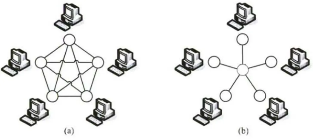
(a) (b)
Figure 2.1: Number of bidirectional translators needed for data exchange: (a) without neutral data format, (N•(N-1))/2 translators; (b) with neutral data format, N translators.
11 2.1. Introduction
implementing translators; (c) vendors are more willing to develop translators to neutral formats because they do not require the disclosure of its proprietary code; (d) changes in one system do not affect translators developed for other systems. Standard neutral data formats also have advantages for long-term data archiving. In many industries, product data must be available throughout the lifecycle of the product (several decades in some cases); archiving using a standard format eliminates the need of keeping old versions of application systems just for accessing old application's native data files, and guarantees that data are accessible in the future, even if the application used to create the data has disappeared. There is an industry-wide agreement that a neutral data format holds the best solution for interoperability problems [4].
During the last decade, significant improvements have been made in the development of standard neutral data formats for product data [5]. However, these efforts have been concentrated on CAD applications, while most CAE applications still lack a neutral data format. This is the case for multibody system (MBS) dynamics, where data standardization is still an open research field [6]. Available simulation tools, commercial and from academic research groups, differ in model description and data formats. The reasons for this situation are in the MBS simulation market characteristics: (a) MBS simulation tools are technically in the early stages compared to mature tools as CAD or Finite Element Analysis (FEA), and therefore they are not widely used yet; (b) during the last years the market has been dominated by a single product, ADAMS [7], which owns more than fifty percent of the market share. The confluence of these factors has kept overall interoperability costs relatively low compared with the costs in the CAD segment, making unprofitable the development of a neutral data format. And vendors are not likely to undertake this effort alone because they often consider proprietary data formats as part of their competitive advantage.
12 Chapter 2. Neutral data models for MBS simulation
1985 1990 1995 2000 2005 2010 2015
Figure 2.2: Evolution of CAD and CAE market shares in the overall PLM (Product Lifecycle Management) market during the last 15 years [8].
Moreover, technologies like MBS dynamics and Computer Fluid Dynamics (CFD) will grow at higher rates than structural analysis, the most used CAE tool now, causing a proliferation of commercial tools and vendors for these applications. With this scenario, exchanges of CAE product data will increase significantly, and also the costs derived from poor interoperability. Therefore, developing standard neutral data formats for these applications is of great interest. Efforts have started for some CAE segments: a neutral format for Finite Element Analysis (FEA) of structural components, ISO 10303-209 [9], has been published in 2001 as part of the ISO 10303 standard for product data representation and exchange, also known as STEP [5]. A similar standard for CFD is under development [ 10]. Interoperability needs in MBS simulation have not been addressed yet, and the MBS community should start to do it as soon as possible.
13 2.2. State of the art
that neutral format, ready to be used as input data for solvers. Standardization of output data (analysis results) would allow decoupling solver and post-processor, making easier to compare results generated by different solvers.
A neutral data format for MBS would be a great benefit for the industry users of this technology, but also for the research community. As stated before, this CAE segment has not reached a mature state yet, and it is a very lively and promising research subject [6]. Most of the research is done using in-house developed codes that use custom formats for input and output data, making very difficult to share models and results between research groups. A neutral format would eliminate these interoperability problems, speeding up the research progress.
This chapter is organized as follows: Section 2.2 presents a review of previous works in the area of standardization of engineering data. Section 2.3 defines the requisites for a MBS neutral data format. Section 2.4 analyzes the current interoperability status in commercial MBS simulation tools. Sections 2.5 and 2.6 describe STEP and XML, two popular standard data formats. Section 2.7 evaluates and compares STEP and XML as candidates to develop a MBS neutral data format. Section 2.8 presents a XML-based prototype implementation of such a format, and Section 2.9 presents a pre-processor prototype for that format. Finally, Section 2.9 provides conclusions and areas of future research.
2.2 State of the art
14 Chapter 2. Neutral data models for MBS simulation
different software applications. Automatic exchange mechanisms were needed. By the same time, the idea that data should be described in a manner that was independent of particular users or computer technologies emerged, and started the research in formal methods for information modeling.
This section starts with an introduction to information modeling, an essential tool for developing robust data formats, followed by a historical review of standardization efforts in the field of engineering product data, and in particular, multibody systems data.
2.2.1 InformaNon modeling
The goal in information modeling is to describe real world data so that it can be processed and communicated efficiently as information without knowledge of its source and without making any assumptions or interpretations. To achieve this goal, both the exchanged data and its interpretation rules need to be explicitly defined, and all parties in the communication process must operate with the same set of defmitions. Due to the high complexity of engineering product data, neutral data formats for this field must be designed using information modeling techniques.
The development of a neutral data format using these techniques has two main stages: the first one is the design of the model, and the second one is its implementation. Fig. 2.3 shows the different components and software tools that can be present in the process of information modeling.
2.2.1.1 Model design
2.2. State of the art 1 S
1
Validators Information model
(formal description) ^^_t^J
Editors
• GraphicaUlexical Transf. engines
^
Encoding rules \ ^ Code generation
• Formal/infocmal J • Manual/automatic
7 1 i
^Application Validators
^ Programming ^^, Interface (AP[)
:J ^ead Editors
^
• File (text/binary)
^ • Relational DB • Early/late binding Transf. engines
• Object oríented DB • Prog.language
Applications
Figure 2.3: The process of information modeling.
16 Chapter 2. Neutral data models for MBS .simulation
representing major data structures, and connections between icons to represent relationships such as constraints, memberships, etc. Several languages based on graphical representation have been developed during the last decades [5]: NIAM (Nijssen Information Analysis Methodology), known today as ORM (Object-Role Modeling), was rooted in linguistics; IDEFO (Integration Definition for Function Modeling) and its variants IDEF 1 and IDEF 1 X were developed by the United States Air Force between the 1970s and the 1980s, and they are well suited for developing database implementations. In the field of software engineering, several existing modeling languages converged into UML (Unified Modeling Language [11]), which today is the standard language for object oriented analysis and design.
Lexical repre.sentations (also known as .schema.s) use words and
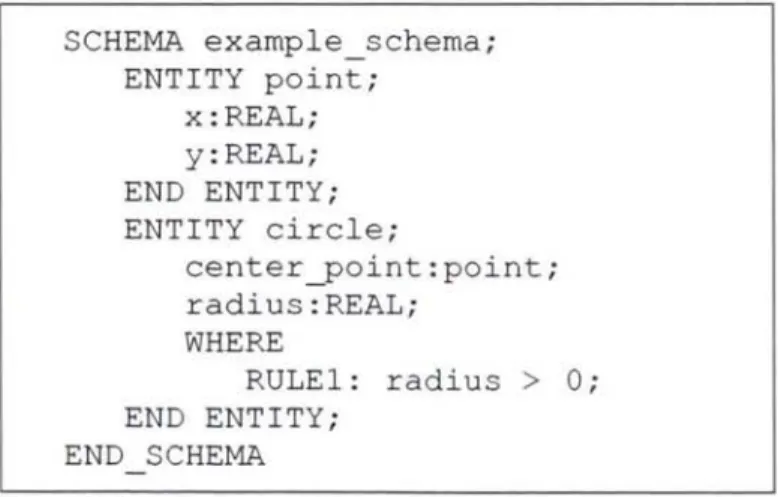
mathematical symbols to represent data and relationships within a model. Similar to programming languages, they offer built-in datatypes and capabilities to define new types and specify constraints on data values. The power of a modeling language is measured taking into account its capabilities to represent complex data structures in an intuitive way, and to impose constraints on data values. Constraints are very important for engineering data, because they enforce data integrity. For example, an input data file for a MBS tool may have a correct syntax but it is useless if it contains a negative mass; the model must impose the constraint "a mass value cannot be negative". Another important feature of lexical representations is that they are computer-interpretable; this capability delivers many advantages in the implementation stage. Some examples of lexical representation are EXPRESS [ 12] and XML Schema [ 13].
17 2.2. State of the art
Several software tools can be used to develop information models. Validators parse the model and check if it follows the syntax and grammar rules of the used modeling language, that is, if the model is valid. Editors help to create, view and modify models. Editors for lexical representations usually incorporate syntax highlighting (as editors used in programming environments) and model validation. Tran.sformation engines apply a set of given rules (which are formally defined in a special language) to an input model in order to generate an output model. This allows generating partial views, simplifications or extensions of a model, without loosing associativity: if the original model is updated in the future, the transformation can be applied again to generate updated derived models.
Although an information model aims to be complete and unambiguous, an informal description is often necessary to provide contextual information, explain the overall model structure, justify modeling decisions, provide examples and define constraints that cannot are not supported by the modeling language. Therefore, both descriptions (informal and formal) and necessary for complex models. Some modeling languages allow inserting comments within the formal model definition, providing a hybrid description format.
2.2.1.2 Model implementation
The implementation of an information model involves two tasks: the definition of a data format for permanent storage of information, and the development of an Application Programming Interface (API) to manipulate the data from a computer program.
18 Chapter 2. Neutral data model.s for MBS .simulation
search and retrieval. However, when databases are used, complex software must be used to manage the information (database servers), and the user needs special tools to access to that information in an intuitive way (database clients). On the other hand, the document approach stores information in a file. Files are managed directly by the computer file system, and no special software is needed. The file format can be binary, which provides better processing performance and smaller sizes, or textual, which is human readable (a very valuable feature) and platform independent, at the cost of bigger size and slower performance. The document approach, especially when text formats are used, has all the advantages that databases lack: information is managed and accessed without special software and documents can be copied, e-mailed and printed easily. In addition, structured file formats can very well represent the structure of real systems without the complexity burden of object-oriented databases. But this approach has also disadvantages: information processing is difficult. Since there is wide variety of file formats (almost every application uses its own format), there are no standardized techniques for parsing the document syntax and custom programs must be developed. Moreover, if the document syntax is very complex, writing compliant parsers can be cumbersome.
Once the data format for permanent storage is defined, a second problem remains to be solved: how applications will access data in that permanent storage. A naive solution is to let each application developer deal with this task independently; in this way, each application has its own code to read and write data. A better approach is to define a common Application Programming Interface (API) to manipulate the data from a computer program. This API is
made up by a set of data structures that mimic the information model, and functions to populate these structures with data read from the permanent storage, manipulate them and write data back to the permanent storage. This common API can be used and shared by all kind of applications dealing with this data format, which makes software development easier. The API can be implemented in procedural programming languages, like Fortran or C, or in object-oriented programming languages like C++ or Java.
19 2.2. State of the art
understand the information model and the data format for permanent storage, and then design and write code for the data structures and routines. Automatic generation is performed by a software tool that can interpret a lexical
representation of the information model and generate the corresponding API to read from and write to a predefined format of permanent storage. These kinds of tools are available for some modeling languages, and provide a very significant improvement in softwaze development productivity. However, if the format for permanent storage is not the same predefined format for which the tool has been designed, the tool can seldom be used without modifications. These modifications are also time-consuming, and they only pay off if the information model is big and complex. Otherwise, manual generation is faster.
APIs can use an early binding or a late binding. In late bindings, the API data structures represent the concepts supported by the modeling language used to describe the information model. In early bindings, the API data structures represent the concepts defined in the information model. As example, suppose that a modeling language that supports the concepts of "object" and "property" is used to describe an information model for a caz. The information model defines a"car" as an object, which have properties like "numberOfDoors", "color", etc. Then, a late binding would provide functions like getObject("car") or getProperty("numberOfDoors"), whereas an early binding would provide functions like getCarO or getNumberOfDoorsQ. It is clear that a late binding API generated for a given modeling language can be used to manipulate any information model described with that language. On the other hand, an early binding API must be generated specifically for a particulaz information model, thus delivering two advantages -better performance and ease of use- because the structures and functions used are related to the domain model (cars and number of doors), not to the information model (abstract objects and properties).
20 Chapter 2. Neutral data modeLs for MBS.simulation
modeling language and a data format. Editor.s help to create, view and modify models. Transformation engines apply a set of given rules to an input data set in order to generate an output data set. This allows easy updating of data to newer versions of the format for permanent storage, translation of data into other formats, etc. Finally, general-purpose applications (such a MBS simulation tool) use the API to read and write data, and the validator to check data integrity.
2.2.2 Neutral data formats for engineering product data
In the early 1970s, computer-aided design (CAD) tools revolutionized product data representation, and companies from automotive and aerospace industries were the first to incorporate this technology into their product development process. At the end of that decade, those industries were frustrated by the lack of exchange mechanisms between their CAD systems, and forced vendors to start standardization efforts. The need for neutral data formats fostered the development of information modeling, and in few years, the first standards were proposed.
21 2.2. State of the art
almost every CAD system and in many engineering analysis software as well. The European Commission also contributed to product data standardization with the ESPRIT project called CAD*I (CAD Interfaces), which involved six European countries. The project worked mainly in product model data exchange and on data exchange for finite element analysis (FEA).
Similarly, other industries made efforts to develop data standards for their product segments, such as EDIF (Electronic Design Information Format [18]) and VHDL (Very High Speed Integrated Circuit (VHSIC) Hardware Description Language [ 19]), developed by The Institute of Electrical and Electronics Engineers (IEEE), and POSC (Petrochemical Open Software Consortium [20]) for oil and gas. The use of all these standards in 1995 was reported in [5] (Table 2.1).
Table 2.1: Use of standards per sector ( • = moderate; •• = widely)
Sector IGES SET VAD-FS DXF EDIF VHDL POSC
Aerospace • • • •
Automotive • • • • •
Building & Construction ••
Process plant • • •
Oil and gas • ••
Shipbuilding • •
Electrical / Electronic • • • • •
Consumer goods • •
22 Chapter 2. Neutral data models for MBS simulation
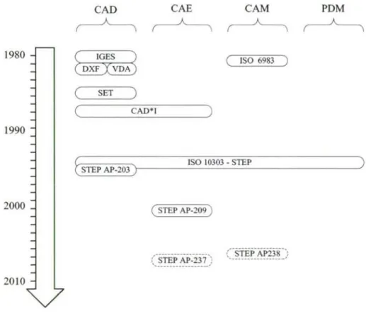
international effort to create an international standard that enabled the capture of information comprising a computerized product model in a neutral form, without the loss of completeness and integrity, throughout the lifecycle of a product. Ten years later, the ISO 10303 standard for product data representation and exchange, also known as STEP, was published.
CAD CAE CAM PDM
1980 -I
ISO 6983
1990 ^
SET
CAD*I
STEP AP-203
ISO 10303 - STEP
2000 ^ STEP AP-209
2010 ^
v
-- ---
^ STEP AP-237 ;^
-- --- ^; STEP AP238
-Figure 2.4: Some milestones in the standardization of engineering product data.
23 2.2. State of the art
(STEP AP-209 [9]) and Computer Fluid Dynanúcs (STEP AP237, under development [ 10]). A new standard for CNC manufacturing, STEP AP238, also known as STEP-NC, is also under development to replace the old ISO 6983 (the popular G-Code).
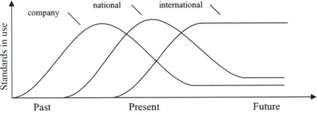
STEP is replacing other neutral data formats. Since the publication of STEP, no more national standards have been proposed for product data, and old standards like IGES, that have been updated regularly since its publication, are about to reach the imal revision, in favor of STEP equivalents. This is the general trend in the use of standazds: users are moving from company and national standards towards international standards (Fig. 2.5).
national international \
company \
Past Present Future
Figure 2.5: Trend in the use of standards for data exchange.
2.2.3 Data formats in MBS software
24 Chapter 2. Neutral data models for MBS simulation
they often find information modeling technologies difficult to apply when solving interoperability problems.
It may seem surprising, but many software applications currently used for MBS research do not even have any data input from an external source. This is true for many in-house developed codes that are used to implement and test new formulations. In these cases, the description of the multibody system (properties and equations for kinematics and dynamics) is hard-coded directly in the source code of the program and linked to a set of solver routines. The resulting program is a custom solver for a particular mechanism. Developing this type of applications has two advantages: knowledge on information modeling is not required, and the hard-coding of the system properties and equations reverts in very fast simulations. But this method also has important disadvantages: reutilization of code is difficult and users developing new models must have advanced programming skills.
♦ _
^Data format for , permanent storage
read Application
• File (text)
Figure 2.6: Simple data modeling in MBS codes.
25 2.2. State of the art
documentation, together with the description of the data format for permanent storage (usually text files). In many cases, there is not an intermediate API to read and write data: this functionality is directly embedded in the application code. Data are read and used directly to populate the internal data structures used by the solver. Developing the simulation application without an intermediate API layer is probably easier and faster for implementing a given MBS simulation method: it tackles the core of the problem and does not have to take into account any aspects of API design and programming. But an input data format without an API is difficult to share: application willing to read and write to this format will need to develop its own set of reading and writing routines. Routines of the first application cannot be reused, because the internal structures used by the applications are probably different. Therefore, the lack of an intermediate API layer is an important obstacle to data exchange and share.
mbs Formalisms
^
^^ Simulation
param part
^^
interact
^^
global
^--ĵ Visualization
frame bodv member connect
' "I
joint (orce
Figure 2.7: Structure of the DFG multibody system package, as described in [22].
26 Chapter 2. Neutral data models for MBS .simulation
reference systems) and interactions (joints, forces, etc.); integrity constraints can be imposed and checked. A detailed description of the model can be found in Otter et al [22]. Seybold et al described this data model using the EXPRESS modeling language [24], allowing the use of automatic code generators and easy permanent storage in an object-oriented database system. This system served as common data repository for a suite of multibody analysis tools: kinematics, dynamics, visualization, etc. Wallrapp extended the model to support flexible bodies based on a modal representation of small body deformations [25]. The original software package was implemented in Fortran 77, but later an implementation in C language called DAMOS-C (DAta model for MultibOdy Systems) was proposed by Daberkow and Schiehlen [26]. This C implementation provided a higher lever of reusability and better integration with CAD systems, as demonstrated by Daberkow and Kreuzer [27]. It was extended to support mechatronic systems, and translators to other data formats (ADAMS, SYMPACK, DADS, etc.) were developed. DAMOS-C used state-of-the-art technologies at the time of being developed, but this happened almost ten years ago, so it could not exploit modern technologies available now. As example, despite having an object-oriented data model, DAMOS-C was implemented in C (not object-oriented) instead of C++ (object-oriented) to assure portability and good integration with other systems (as CAD tools). Now C++ has very good portability and it is the standard interface for many CAD applications, so a C++ implementation would have many advantages. In addition, neither the DAMOS-C software nor the corresponding detailed documentation is publicly available, so the system cannot be used as a neutral standard data format by other users.
27 2.2. State of the art
Outside of Germany, coordinated efforts or contributions to standardization of multibody systems data are almost inexistent. An interesting approach was taken by Tisell and Orsborn with the development of MECHAMOS [29,30], a prototype of MBS analysis tool based on the object-relational database management system AMOS. Matlab and MapleV are used as computational engines to perform numeric and symbolic analyses, and the multibody system is described using AMOSQL, a database-oriented query language. The system has good capabilities to manage large amounts of data in an efficient way, but the input format is rather verbose and too database-oriented.
2.2.4 Other data formats of interest
Recently, XML (Extensible Markup Language [31]) has emerged as an increasingly popular format to encode information. XML is a simple, very flexible text format derived from Standard Generalized Markup Language (SGML, ISO 8879) which was developed in the 1970s for the large-scale storage of structured text documents. The XML specification was published in February 1998 [31] by the World Wide Web Consortium [32], the organization responsible for defming many internet-related standards, most notably HTML. Originally designed to meet the challenges of large-scale electronic publishing, XML is also playing an increasingly important role in the exchange of a wide variety of data on the Web and elsewhere. It has become the preferred format for transferring business information across the Internet, receiving widespread endorsement from industry and governments.
2.2.5 Summary
28 Chapter 2. Neutral data model.s for MBS simulation
countries (like Germany) have made important standardization efforts and very interesting projects have been proposed, but results are far from being considered international standards and none of them have achieved a widely use in industry of research.
Currently, STEP and XML are the most promising technologies for data standardization, and they should be considered as candidate frameworks to develop a neutral data format for multibody system analysis. Both technologies are described and evaluated in Sections 2.5, 2.6 and 2.7.
2.3 Requirements for a neutral MBS data format
Before evaluating the suitability of available technologies to develop a neutral data format for multibody systems, requirements for such a format must be clearly defined. Both the model and its implementation methods must be designed in order to accomplish three main requirements: (a) foster data reutilization, (b) foster data exchanging and sharing, and (c) streamline the acceptance into the research community.
2.3.1 Foster data reutilization
29 2.3. Requirements for a neutral MBS data format
• Split the description of a simulation into three logical sections: the model of
the multibody system, the analysis to be performed on it, and the method to be used to perform the analysis. This organization provides maximum decoupling and allows easy combination of different methods to perform different analysis on different models.
• Support submodels. With submodels, complex engineering systems can be
decomposed into small modules to make them efficiently treatable: each module can be developed and tested by a different team of engineers, and then assembled with other modules to build the whole system.
• Support parametric models. In a parametric model, any numerical quantity can be defined by a symbolic expression that depends on other quantities and a given set of parameters. Parametric models are essential for optimization analysis, but they can also increase the reusability of data: the combined support of submodels and parametric models enables to develop libraries of generic parametric components that can be adapted (by specifying values for the parameters) and used as submodels of more complex systems.
• Apply units at local scope. If units are defined at global scope (the same unit
system is used for the whole model), problems may arise when merging models that were created using different unit systems.
• Provide flexible including and merging mechani.sms. The three previous requirements allow creating reusable models, but in order to use them to build new models, tools to include submodels or merge models must be available. These tools should be as flexible as possible, allowing, for example, to inclusion offragment.s of existing models instead of the whole model.
2.3.2 Foster data exchanging and sharing
30 Chapter 2. Neutral data models for MBS simulation
data needs to be accessed by different kinds of applications (pre-processors, solvers and post-processors), and each research team uses different software systems (commercial or homemade). Therefore, data exchange is essential for collaboration between teams. The goal of a neutral data format is to streamline the data exchange, but a higher level of collaboration can be achieved if the data format supports data sharing. Data sharing goes further than simple data exchange. Data exchange means that a given software system maintains the master copy of the data internally and exports a snapshot of the data, which is imported by other application. Since data imported into the second application is not synchronized with respect to the "master" copy of the data contained in the originating software system, problems arise. Data sharing means that a master copy of the data is stored in a centralized repository, and is accessed by all applications. Data is not duplicated in each application, and synchronization problems do not exist [S]. A neutral data model must:
• Provide a neutral data model independent on the formalism or application
used to perform multibody system simulations. Modeling concepts that are meaningful only to a particular formalism must be avoided. In this way, neutral data can be used as input for different simulation tools. This is the basis for data exchanging.
• Provide distributed access to the data. Today the Internet provides a
ubiquitous platform for connectivity and collaboration: data can be accessed in a transparent way using friendly and easy-to-use software (web browsers), regardless it storage format or localization. A neutral data format should provide tools to access data in a similar way. This is the basis for data
sharing.
2.3.3 Streamline the acceptance into the research community
31 2.3. Requirements for a neutral MBS data format
reutilization and sharing, but their implementation is too complex for mechanical engineers without extensive knowledge about object-oriented databases. It is very important to facilitate the acceptance into the research community, because researchers will be the first users of neutral data formats. Vendors of MBS analysis tools are not likely to provide neutral data formats without pressure from the users, because they often consider proprietary data formats as part of their competitive advantage. This barrier does not exist in the research community, which can get great benefits from data sharing. Therefore, a neutral data model must:
• Be configurable. Not all users of MBS analysis tools need the same
functionality. The range of phenomena that can appear in a multibody system is quite wide: flexibility, contact, impacts, friction, clearances, etc. If we try to develop a neutral data format able to support all these phenomena, its design would take years and the resulting model would be extremely complex and difficult to understand. A model made up by small, modular components is better than a big monolithic model. Users can adapt, configure or extend it to fit their particular needs.
• Be easy to implement. Mechanical engineers are not experts on computer
science, so the software tools required for working with a given data model must be ready available and easy to use. Application Program Interfaces for accessing and manipulating data should be ready available, in order to reduce software development efforts.
• U.se low cost technologies. Many small academic groups and individual
researchers have low economic resources. If the software tools needed to work with the data model have expensive licenses, the implementation of such a data model will be restricted to industrial companies and a few academic teams.
32 Chapter 2. Neutral data model.s for MBS . simulation
2.4 Evaluation of commercial MBS software
After identifying the requirements for a MBS neutral data format, the data formats used by commercial MBS tools should be studied and evaluated against those requisites. This evaluation will provide understanding about the capabilities offered by current tools, which should be leveraged by a neutral format, and will identify problematic issues in data modeling, which should be avoided by the neutral format.
2.4.1 Software selected for the evaluation
Four commercial general-purpose MBS simulation tools have been selected for evaluation: ADAMS, DADS, SIMPACK and RecurDyn. These four products cover more than 70% of the market share, and all of them offer high end capabilities: rigid and flexible bodies, contacts, user-defined functions, control, etc. Two of the applications (ADAMS and DADS) are based on reference coordinates and global formulations, while the others (SIMPACK and RecurDyn) are based on relative coordinates and recursive formulations.
ADAMS (Automatic Dynamic Analysis of Mechanical Systems) is the most
popular software for MBS analysis and dominates the market with more than 50% of the market share. Based on the programs developed by Chace and Orlandea at University of Michigan in the early 1970s, ADAMS started to be commercialized in 1977 by the U.S. based corporation Mechanical Dynamics, Inc. (MDI). Currently, it is maintained and distributed by MSC Corporation [7].
DADS (Dynamic Analysis and Design System) was written in the late 1970s
by professor Haug at The Universiry of Iowa, and commercialized by the U.S. based corporation CADSI. Version 9.6 was the last release of DADS as an independent application: its solver is now integrated into the LMS Virtual.Lab CAE suite and commercialized by LMS International under the name of LMS Virtual.Lab Motion [33].
SIMPACK was developed in the early 1980 by the group of Kortiim at the
33 2.4. Evaluation of commercial MBS software
analysis tools developed at DRL since the 1970s, like Fadyna and Medyna, and now it is maintained and distributed by Intec GmbH [34].
RECURDYN (RECURsive DYNamics) was released in 2000 by the Korean
company Function Bay [35]. Its solver is based on recursive methods proposed by Bae at Hanyang University (Seul, Korea). RecurDyn is the newest tool of the four evaluated systems, and its market share is small (it has recently reached the 100^ industrial user), but it is having a great success in Asia.
2.4.2 Evaluation criteria
Several criteria related to the ability to reuse, exchange and share data with other MBS analysis tools have been considered:
• Format for data storage.
• Import from and export to other MBS formats. • Formalism-independent modeling.
• Support for sub-models. • Support for units systems. • Support for parametric models.
2.4.2.1 Format for data storage
34 Chapter 2. Neutral data models for MBS simulation
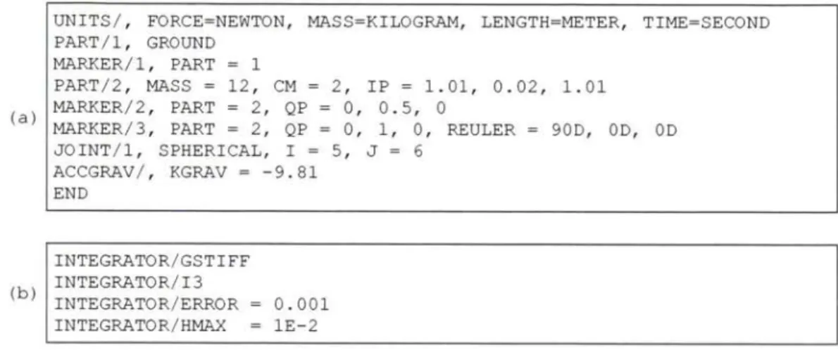
ADAMS provides two text-based secondary storage formats: the .ADM format and the .CMD format. The purpose of the .ADM format is to store commands executed in ADAMS preprocessor, while the .CMD format is targeted at serving as input for the solver. The data given to the solver are split into two files: the first one describes the multibody system, and the second one defines the analysis to be performed and the method used. Examples of both files are shown in Fig. 2.8.
UNITS/, FORCE=NEWTON, MASS=KILOGRAM, LENGTH=METER, TIME=SECOND PART/1, GROUND
MARKER/1, PART = 1
PART/2, MASS = 12, CM = 2, IP = 1.01, 0.02, 1.01 MARKER/2, PART = 2, QP = 0, 0.5, 0
(a)
MARKER/3, PART = 2, QP = 0, 1, 0, REULER = 90D, OD, OD JOINT/1, SPHERICAL, I= 5, J= 6
ACCGRAV/, KGRAV = -9.81 END
INTEGRATOR/GSTIFF INTEGRATOR/I3
(b)
INTEGRATOR/ERROR = 0.001 INTEGRATOR/HMAX = lE-2
Figure 2.8: Fragments of ADAMS input data files: (a) model description, (b) analysis
description.
DADS uses a similar text format as secondary storage format. ADAMS text format has several limitations: it uses integer numbers as identifiers for model elements, which is not very intuitive compared with text identifiers, and all the information is given in a single file and it is not structured. In addition, the information about the initial conditions for the analysis is mixed with the description of the system topology. This makes impossible to reuse a given topology to perform several simulations with different initial conditions.
35 2.4. Evaluation of commercial MBS software
joints, forces, contact information, flexible bodies) is stored under a different subdirectory.
gravity ( 3) _ -9.810E+00 ! [m/s^2] g-vector
refsys ( $B_Isys) = 1 ! Type of kinematic movement
marker (1, $M_Isys) _ $B_Isys ! Assignment
! Bodies: (a)
body.m ( $B_Bodyl) _ .10000E+01 ! [kg] mass
body.I (1,1,$B_Bodyl) _ .10000E+02 ! [kgm^2] I_Tensor
body.I (2,2,SB_Bodyl) _ .10000E+02 ! [kgm^2] I_Tensor
body.I (3,3,$B_Bodyl) _ .10000E+01 ! [kgm^2] I_Tensor
t = O.OOOOOOOO00E+00 ! Initial Time for TimeIntegration tend = 1.0000000000E+00 ! EndTime for TimeIntegration ntout = 101 ! Number of Communication Points iintv = 8 ! Integration Method: SODASRT
(b) iatol = 1 ! atol & rtol: 1=scalars, 4=vectors
atolg ( 1) = 9.9999997474E-05 ! Absolute Error Tolerance Group rtolg ( 1) = 9.9999997474E-05 ! Relative Error Tolerance Group vipar ( 1) _-1.0000000000E+00 ! Maximal RightHandSide Calls vipar (12) = 2.0000000000E+00 ! Using Root-Funktion (1=no, 2=yes)
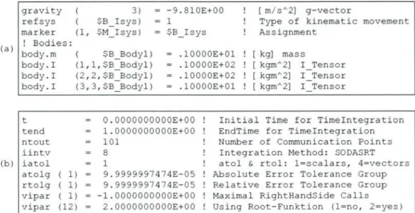
Figure 2.9: Fragments of SIMPACK input data files: (a) model description, (b) analysis description.
2.4.2.2 Import and export other MBS formats
Only DADS and RecurDyn provide import capabilities for ADAMS text files in their preprocessors. SIMPACK can import models from other MBS analysis systems (CATIA Kinematics and Pro/Engineer), but they are not considered because these systems have a very low market penetration. None of the systems export models to other formats, obviously because the lack of a neutral data format. And none of the postprocessors can import result files generated in other tools.
36 Chapter 2. Neutral data models for MBS simulation
by Schiehlen [6], where a common neutral data format for input and output is shared across different simulation tools.
ADAMS ADAMS ADAMS ADAMS
input preprocessor solver results
RECURDYN RECURDYN RECURDYN RECLJRDYN
input preprocessor solver resulL
D pDS (^ ^ p DADS ^ DADS \,^ DADS
in ut (^^^^ re rocessor solver f^ results
SIMPACK SIMPACK SIMPACK SIMPACK
input preprocessor solver results
Other Other Other Other
input preprocessor solver results
Figure 2.10: Current situation for MBS simulation software.
ADAMS
postprocessor
RECURDYN
postprocessor
DADS
postprocessor
SIMPACK
postprocessor
Other postprocessor
Figure 2.11: Desired situation for MBS simulation software, according to Schiehlen [6].
2.4.2.3 Formalism-independent modeling
37 2.4. Evaluation of commercial MBS.software
Each body is associated to one and only one joint element. This joint is automatically generated by SIMPACK every time a new body element is defined, and it cannot be deleted nor can new joints be defined. When defining the markers associated with a joint, it is necessary to follow the tree structure that starts from the inertial frame and moves outwards. If extra joints are needed due to kinematically closed loops, they must be applied as constraint elements. It is at the discretion of the user to decide which joints in a closed loop should be modeled as constraints.
^
^ 3 C
' ///////////////////////
2
^ 3 ^
^///////////////////// %i
Figure 2.12: Modeling of kinematically closed loops in SIMPACK.
38 Chapter 2. Neutral data models for MBS simulation
RECURDYN is also based on a recursive formalism, but kinematically closed loops are processed in a transparent way for the user's point of view. This can be annoying for users that wish to take full control of the solution method. The best solution would be to provide users an option for specifying which joints should be substituted.
2.4.2.4 Support for sub-models
ADAMS and DADS do not support sub-models. Models can be merged, but the resulting models do not have a hierarchical structure. RECURDYN supports sub-models of any deep, but in order to use an existing model as a sub-model, a special pre-processing is needed. SIMPACK supports sub-models limited to one level. SIMPACK provides a useful capability for building symmetric complex models: a sub-model can be reflected about an axis when imported to another model.
2.4.2.5 Support for units of ineasure
All applications support different unit systems. ADAMS, DADS and RECURDYN are based on the MLT system (units are derived from the basic dimensions of Mass, Length and Time) and offer several predefined systems (MKS, CGS, etc.). SIMPACK is more flexible: it can assign a separate unit to each individual dimension; for example, length can be defined in m and velocity in mm/s.
The important issue is that all of them define units at global scope, which means that the units system is set for the entire model and cannot be modified for individual modeling elements. This can be a source of trouble when the user tries to combine or merge sub-models that use different units systems, because conflicts may arise.
2.4.2.6 Support for parametric models
![Figure 2.2: Evolution of CAD and CAE market shares in the overall PLM (Product Lifecycle Management) market during the last 15 years [8]](https://thumb-us.123doks.com/thumbv2/123dok_es/7029869.312180/22.757.168.587.127.314/figure-evolution-market-shares-overall-product-lifecycle-management.webp)
![Figure 2.11: Desired situation for MBS simulation software, according to Schiehlen [6]](https://thumb-us.123doks.com/thumbv2/123dok_es/7029869.312180/46.759.129.636.536.745/figure-desired-situation-mbs-simulation-software-according-schiehlen.webp)