RENÉ PEINADOR DÁVILA
UNIVERSIDAD DE VALLADOLID
CHARACTERIZATION OF
ULTRA AND NANOFILTRATION
COMMERCIAL FILTERS BY
LIQUID-LIQUID DISPLACEMENT
POROSIMETRY
CHARACTERIZA
TION OF
UL
TRA
AND NANOFIL
TRA
TION
COMMERCIAL
FIL
TERS BY
LIQUID-LIQUID DISPLACEMENT
POROSIMETR
FACULTAD DE CIENCIAS
DEPARTAMENTO DE FÍSICA APLICADA
TESIS DOCTORAL
CHARACTERIZATION OF
ULTRA AND NANOFILTRATION
COMMERCIAL FILTERS BY
LIQUID-LIQUID DISPLACEMENT
POROSIMETRY
MEMORIA PARA OPTAR AL GRADO DE DOCTOR PRESENTADO POR
René Israel Peinador Dávila
Dirigida por: Dr. José Ignacio Calvo Díez
AUTORIZACIÓN DEL DIRECTOR DE TESIS
(Art. 2.1. c de la Normativa para la presentación y defensa de la Tesis Doctoral en la UVa)
D. José Ignacio Calvo Díez, profesor del Departamento de Física Aplicada de la Facultad de Ciencias, como Director de la Tesis Doctoral titulada:
CHARACTERIZATION OF ULTRA AND NANOFILTRATION COMMERCIAL FILTERS BY LIQUID-LIQUID DISPLACEMENT POROSIMETRY.
presentada por D. René Israel Peinador Dávila, alumno del programa de Doctorado en Física, impartido por el departamento de Física Aplicada,
Considero que dicha tesis recoge el trabajo realizado por el interesado a lo largo de varios años, conteniendo aspectos novedosos de investigación sobre la técnica de desplazamien-to de fluidos, aplicada a membranas sintéticas, que la hacen merecedora de su defensa y aprobación.
Por todo ello, autorizo la presentación y defensa de la misma.
Valladolid, 15 de mayo de 2013
El Director de la Tesis,
Fdo.: José Ignacio Calvo
No basta saber, se debe también aplicar.
No es suficiente querer, se debe también hacer.
Goethe
Poeta, dramaturgo y científico alemán
A mis padres
y especialmente
AgrAdecimientos
Al finalizar un trabajo tan arduo y lleno de dificultades como el desarrollo de una tesis doctoral es inevitable padecer un muy humano egocentrismo que te lleva a con-centrar la mayor parte del mérito en el aporte que has realizado, pero en cambio si lo analizamos objetivamente te demuestras inmediatamente que la magnitud de este aporte hubiese sido imposible sin la participación de muchas personas e instituciones que han facilitado mi evolución para que este trabajo llegue a un feliz término. Por ello, es para mí un verdadero placer utilizar este espacio para ser justo y consecuente con todos ellos, expresándoles mis agradecimientos.
Debo agradecer de manera especial y sincera a mi director de tesis el Dr José Ignacio Calvo Díez por haberme dado la oportunidad de aceptarme bajo su dirección. Su apoyo y confianza en mi trabajo y su capacidad para guiar mis ideas, ha sido un aporte incalculable, no solamente en el desarrollo de este trabajo, sino también en mi formación como investigador. Orientación, flexibilidad y rigurosidad en el campo científico, han sido clave del buen trabajo que hemos realizado juntos, el cual no se puede concebir sin su siempre oportuna participación, agradeciéndole en todo momento el haberme facilitado siempre los medios suficientes para llevar a cabo todas las actividades propuestas durante el desarrollo de esta tesis.
Quisiera extender también este agradecimiento a los Dres Antonio Hernández Ji-ménez, Laura Palacio Martínez y Pedro Prádanos del Pico, todos ellos “cabezas” indiscu-tibles del SMAP y docentes de la Universidad de Valladolid, con quienes he compartido estos buenos años de trabajo y quienes han estado a mi lado en todo momento.
A todos mis “colegas” de laboratorio, a los que siguen y a los que ya no están, les doy las gracias por haberme apoyado y hecho pasar excelentes momentos: Alberto, Ál-varo, Andrea, Blanca, Fernando, Gloria, Liliana, Miguel, Noemí, Raquel, Roberto, Sara, Youssef.
Mis más sinceros agradecimientos a todo el personal del departamento de Física Aplicada, José Carlos, Isaías, Felipe.... y, en especial a Isma, agradecerles sinceramente su apoyo.
También quiero agradecer este trabajo a Juan Marcos Sánz Casado, compañero de estudios y exponente fundamental de esta técnica, dejándome un impresionante legado, siendo el hilo conductor en su implementación y desarrollo, junto a Pablo y Valeriano en las arduas tareas de programación.
y en especial a Mari Carmén Almécija, compañera de trabajo en diferentes estancias, así como en lo personal.
A mis compañeros de laboratorio de investigación y desarrollo, en mi estancia en Sartorius Stedim Biotech® en Göttingen, entre ellos, Celia, Pedro, Thobias, Jan, Roberto, Verónica, ...
A los miembros del Departamento de Química y Química Industrial de la Univer-sidad de Génova, entre los que destaco afectuosamente a Giorgio, Antonio Comite, Silvia, Rafaella por su cálida acogida y especialmente a los Profesores Capanelli y Bottino, por su infinita ayuda, profesionalidad y experiencia en esta técnica, siendo ellos los auténticos pioneros en este campo.
Grazie mile con tutto il cuore
I would like to acknowledge Dr. Volkmar Thom and Kuong To-Vinh, from the R&D Departament of Sartorius-Stedim Biotech®, at Göttingen, for the opportunity they gave me to introduce in research through a collaboration with them, and for the kindness they offered me, which I would never forget.
Ich danke Ihnen sehr
Para todos aquellos que omito por falta de memoria, sin intención de restarles im-portancia, les agradezco enormemente su apoyo también.
Por último, quiero agradecer a todos mis amigos, que me han brindado su cariño y comprensión en todo momento, siempre atentos a mi evolución, Ángel, Héctor, Gabi, Rubén, Luis Carlos, Fernan, Patri, Jaime, Guty y por supuesto a toda mi familia, quienes me han apoyado con cualquier decisión que he tomado y quienes continuamente me ani-man a continuar en este intenso, pero apasionante camino de la investigación científica.
Acknowledgements
Sartorius-Stedim Biotech® is acknowledged for funding through contract
061/074251 with the Fundación General de la Universidad de Valladolid, including a grant for the author during the period of the experimental work of this thesis.
Contents
resumen / AbstrAct i-iii
orgAniZAciÓn de LA memoriA / thesis outLine v-vi
objetivos / scopes vii-viii
1
OVERVIEW OF MEMBRANE
SCIENCE AND TECHNOLOGY
1.1 introduction 1
1.2 membrAne mArKet 1
1.3 FundAmentALs oF membrAnes 5
1.3.1 Definition and Classification 5
1.3.2 Membrane Module Design 8
1.3.2 Membrane Material 10
1.4 membrAne processes 15
1.4.1 Pressure Driven Membrane Processes 15
1.4.2 Concentration Gradient Driven Processes 15 1.4.3 Electrical Potential Driven Membrane Processes 16 1.4.4 Temperature Gradient Driven Membrane Processes 16
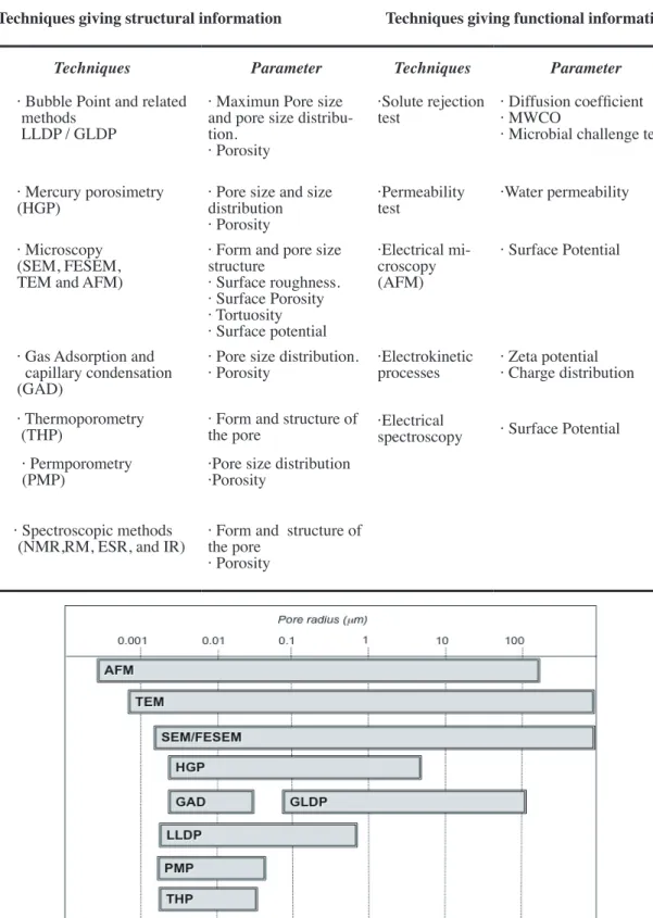
1.5 chArActeriZAtion oF membrAnes 18
1.5.1 Characterization Methods 23
1.5.2 Methods of Liquid Penetration 26
1.5.2.1 Fundamentals 26
1.5.2.2 Bubble Point Method 27
1.5.2.3 Fluid Displacement 27
-Air Liquid Displacement
-Liquid-Liquid Displacement
1.6 concLusions 31
1.7 reFerences 32
2
DEVELOPMENT AND OPTIMIZATION
OF A LIQUID-LIQUID DISPLACEMENT
POROMETER DEVICE
2.1 historicAL 41
2.2 LLdp AnALYsis FundAmentALs 42
2.2.1 Grabar-Nikitine Algorithm 44
2.3 AutomAted LLdp porosimeter 47
2.3.1 LLDP Setup 47
2.3.2 Porosimetric Liquids Preparation 49
2.3.3 LLDP Analysis 51
2.3.4 Data Analysis and Treatment 56
2.4 concLusions 59
2.5 reFerences 60
LIST OF PUBLICATIONS
3
Paper
one
characterization of uF membranes
63
by liquid–liquid displacement porosimetry
4
Paper
two Characterisation of polymeric
72UF membranes by liquid–liquid
displacement
porosimetry
5
Paper
three
Liquid-liquid displacement
89
porosimetry for the characterization
of virus retentive membranes.
6
Paper
four
Liquid-liquid displacement porometry
81to estimate the molecular weight
cut-off of ultrafiltration membranes
I
resumen
La tecnología de membranas aplicada, entre otros, en procesos como la Ultrafiltra-ción (UF) y la NanofiltraUltrafiltra-ción (NF), se ha convertido en una importante parte de los pro-cesos biotecnológicos de separación en los últimos decenios. Su principal característica, la morfología porosa de los filtros, conducente a un “mecanismo de criba”, permite una separación efectiva con altas características de selectividad y realizada en condiciones medioambientales y energéticas muy interesantes.
Ante el desarrollo ingente de los filtros de membrana, se hace necesario un creci-miento en paralelo de las técnicas de caracterización de dicho filtros, como herramientas fundamentales tanto para fabricantes, como usuarios o investigadores.
En este sentido necesitamos conocer de primera mano tanto los parámetros fun-cionales como los estructurales de la membrana, necesarios para una adecuada elección de la misma con vistas a una determinada aplicación.
La cuestión que se nos plantea es la siguiente: ¿Existe algún método de caracteri-zación que, por sí sólo, nos de una visión clara y fácilmente interpretable de la verdadera estructura y funcionalidad del filtro?.
La respuesta a esta pregunta, evidentemente, es nula. Son tantos los parámetros estructurales y funcionales que contribuyen al conocimiento exacto de la membrana, que no hay ninguna técnica que pueda aportarnos toda esta cantidad de información.
Desde el punto de vista industrial y comercial, el parámetro más utilizado y re-querido, con vistas a posibles aplicaciones de los filtros, es el peso molecular de corte (MWCO), aunque es evidente que por sí sólo no constituye una herramienta definitiva para la elección de un filtro de membrana.
La larga experiencia del SMAP en caracterización de membranas nos permite con-cluir que las técnicas porosimétricas dan información muy interesante, relacionada con el tamaño y la distribución de tamaños presentes en una membrana, información que puede ser convenientemente cotejada con aspectos funcionales de la misma.
En ese sentido, la técnica porosimétrica que podemos considerar más prometedora y completa en el rango de Ultrafiltración, es la Porosimetría de Desplazamiento Líquido-líquido (LLDP), la cual nos da información muy importante sobre este tipo de filtros.
Ahora bien, varios problemas se plantean en cuanto a la mejor aplicación de la técnica LLDP:
a) mejorar las condiciones operativas de la técnica, considerada por muchos investigado-res como poco reproducible y complicada desde el punto de vista operativo.
II
que los poros existentes van a estar en el rango cercano al nanómetro.
c) relacionar la información estructural obtenida con datos funcionales, especialmente con el MWCO, a fin de utilizar la técnica LLDP para estimar la aplicabilidad de una membra-na a un proceso de separación dado.
A la mejora de estas cuestiones pretende contribuir la tesis presentada, mediante la mejora de la técnica LLDP, automatizando el equipo LLDP desarrollado en el SMAP, optimizando su forma de trabajo y operación y finalmente, extendiendo al máximo su rango de trabajo, a fin de que pueda cubrir tanto el rango de UF como buena parte de las membranas comerciales de NF.
III
AbstrAct
Membrane Technology applied, among others, in processes such as Ultrafiltration (UF) and Nanofiltration (NF), has become an important part of biotechnological separa-tion processes in recent decades. Its main feature, the morphology of the porous filters, leading to a “sieving mechanism” allows effective separation with high selectivity fea-tures and made in energy and environmental conditions very interesting.
Given the enormous development of membrane filters, it becomes necessary the growth in parallel of characterization techniques applied to such filters, as essential tools for both manufacturers and end-users or researchers.
In this sense we need to know most exactly possible, both functional and structural parameters of the membrane, all necessary for a proper choice of that with a view to a particular application.
The question we must face is: Is there a characterization method, by itself, giv-ing us a clear and easily interpretable picture of the true structure and functionality of the filter?.
The answer to this question is obviously no. There are so many structural and functional parameters that contribute to the exact knowledge of the membrane, that there is no technique that can bring us all this wealth of information.
From the industrial and commercial standpoints, the parameter most used and required, in view of possible applications of the filters, it is the molecular weight cut-off (MWCO), although it is clear that by itself is not a definitive tool for choosing a mem-brane filter.
SMAP group long experience in membrane characterization allows us to conclude that porosimetric techniques give interesting information related to the size and size distri-bution of the pores present in a membrane, information that can be conveniently checked against functional aspects of it.
In this sense, we can consider that Liquid-liquid displacement porosimetry (LLDP) is the most promising porosimetric technique in the range of Ultrafiltration, thus giving us important information about these filters.
However, several problems arise regarding the best application of the LLDP tech-nique:
a) improvement of the operating conditions of the technique, considered by many re-searchers to be poorly reproducible and difficult from the standpoint of operating,
IV
c) connection of the structural information obtained with functional data, especially with the MWCO, to use the LLDP technique for estimating applicability of a membrane to a given separation process.
To improve these issues, the present thesis aims to contribute by improving the LLDP technique, automating the LLDP equipment developed in the SMAP, optimizing the way they work and operates, and finally, extending at the maximum the working range, so that it can cover both the range of UF and most of commercial NF membranes.
V
orgAniZAciÓn de LA memoriA
De acuerdo con la normativa vigente (Ejecución de Acuerdos de la Comisión de Doctorado de la Universidad de Valladolid de fecha 10 de mayo de 2010), esta Tesis Doc-toral se presenta como compendio de publicaciones.
Además de incluir los diversos artículos publicados (Capítulos 3-6) como conse-cuencia del trabajo doctoral, se introduce mediante una síntesis de los conceptos téorico-experimentales mediante una extensa revisión (“state of the art”) de las membranas, los procesos de membranas y las diversas técnicas de caracterización, con especial atención a la técnica de desplazamiento líquido-líquido (capítulo 2). Ambos capítulos introductorios permiten situar y enmarcar los contenidos de los artículos publicados en relación con los objetivos generales perseguidos al comienzo de esta tesis.
Los trabajos incluidos en este documento son los siguientes:
1. characterization of uF membranes by liquid–liquid displacement porosimetry.
J.M. Sanz, R. Peinador, J.I. Calvo, A. Hernández, A.Bottino, G. Capannelli.
Desalination, 245 (2009) 546-553.
2. characterisation of polymeric uF membranes by liquid–liquid displacement po-rosimetry.
René Israel Peinador, José Ignacio Calvo, Pedro Prádanos, Laura Palacio, Antonio Hernández.
Journal of Membrane Science, 348 (2010) 238-244.
3. Liquid-liquid displacement porosimetry for the characterization of virus reten-tive membranes.
René Israel Peinador, José Ignacio Calvo, Khuong ToVinh, Volkmar Thom, Pedro Práda-nos and Antonio Hernández.
Journal of Membrane Science, 372 (2011) 366-372.
4. Liquid-liquid displacement porometry to estimate the molecular weight cut-off of ultrafiltration membranes.
José Ignacio Calvo, René Israel Peinador, Pedro Prádanos, Laura Palacio, Aldo Bottino, Gustavo Capannelli, Antonio Hernández.
Desalination, 268 (2011) 174-181.
VI
thesis outLine
In accordance with current regulations (from the Doctoral Committee of the Uni-versity of Valladolid, dated May 10, 2010), this PhD Thesis is presented as a compendium of publications.
Besides including various published articles (Chapters 3-6) as a result of doc-toral work, it is introduced by an overview of both theoretical and experimental concepts through an extensive review (“state of the art”) of the membranes, membrane processes and various characterization techniques (Chapter 1), with special attention to the tech-nique of liquid-liquid displacement (Chapter 2). Both introductory chapters situate and frame the contents of the articles published in relation to the general objectives pursued at the beginning of this thesis.
The papers included in this document are:
1. characterization of uF membranes by liquid–liquid displacement porosimetry.
J.M. Sanz, R. Peinador, J.I. Calvo, A. Hernández, A.Bottino, G. Capannelli.
Desalination, 245 (2009) 546-553.
2. characterisation of polymeric uF membranes by liquid–liquid displacement po-rosimetry.
René Israel Peinador, José Ignacio Calvo, Pedro Prádanos, Laura Palacio, Antonio Hernández.
Journal of Membrane Science, 348 (2010) 238-244.
3. Liquid-liquid displacement porosimetry for the characterization of virus reten-tive membranes.
René Israel Peinador, José Ignacio Calvo, Khuong ToVinh, Volkmar Thom, Pedro Práda-nos and Antonio Hernández.
Journal of Membrane Science, 372 (2011) 366-372.
4. Liquid-liquid displacement porometry to estimate the molecular weight cut-off of ultrafiltration membranes.
José Ignacio Calvo, René Israel Peinador, Pedro Prádanos, Laura Palacio, Aldo Bottino, Gustavo Capannelli, Antonio Hernández.
Desalination, 268 (2011) 174-181.
VII
objetivos
El objetivo principal de este trabajo experimental es la mejora de la técnica de Po-rosimetría de Desplazamiento Líquido-líquido y su mejor aplicación al análisis de filtros porosos comerciales.
Para la consecución de este objetivo, diversas líneas simultáneas y complementa-rias se han seguido:
a) automatización del equipo LLDP existente en el SMAP de la Universidad de Vallado-lid, equipo desarrollado en cercana colaboración con los Dres. Bottino y Capannelli de la Universidad de Génova,
b) comprobación de las condiciones óptimas de trabajo de las diversas mezclas porosi-métricas, de forma que estas puedan ser convenientemente elegidas en función del rango de poros a analizar o de la interacción de dichos líquidos con las membranas estudiadas, c) estudio teórico de la correlación entre parámetros estructurales y funcionales de los filtros de membrana, buscando conectar la información obtenida de nuestro equipo, con datos funcionales de interés en la aplicación industrial de estos filtros.
Trabajando siempre en dichas líneas, se han realizado varias etapas, que han con-ducido a la publicación de los diversos artículos relacionados en esta memoria. Estas etapas se pueden resumir como sigue:
1) estudio de varias membranas de UF (tanto abiertas y como de poros más cercanos a NF) y análisis de su información porosimétrica,
2) estudio de varias membranas de NF, con diversas mezclas porosimétricas, en condi-ciones extremas de incompatibilidad química con los líquidos habituales,
3) estudio de membranas diseñadas para la retención de virus y correlación de la infor-mación porosimétrica con inforinfor-mación funcional obtenida por variadas técnicas,
4) elaboración de un procedimiento de estimación del peso molecular de corte en mem-branas de UF y NF y comprobación de su validez en un amplio rango de memmem-branas comerciales.
Todas estas etapas, y su exitosa culminación, deberían permitirnos avanzar en lo que consideramos un objetivo primordial de este trabajo y de la línea de investigación del SMAP que lo sustenta:
VIII
scopes
The main objective of this experimental work is the improvement of the Liquid-liquid displacement porosimetry and the best application of this technique to the analysis of commercial porous filters.
To achieve this goal, various simultaneous and complementary lines have been followed:
a) automatization of existing LLDP setup, built-up in the SMAP at the University of Valladolid, equipment developed in close collaboration with Drs. Capannelli and Bottino from the University of Genoa,
b) verification of the optimum working conditions of the various porosimetric mixtures, so that they can be suitably chosen according to the range of pores to be analyzed or the interaction of these fluids with the membranes studied,
c) theoretical study of the correlation between structural and functional parameters of the membrane filters, seeking to connect the information obtained from our setup, with functional data of interest in the industrial application of these filters.
Always working on these lines, there have been followed several steps, which led to the publication of several articles herein. These steps can be summarized as follows:
1) study of various UF membranes (both open and those with pores close to NF) and analysis of their porosimetric information,
2) study of various NF membranes by using several porosimetric mixtures, in extreme conditions of chemical incompatibility with the usual liquid pairs,
3) studying membranes designed for retention of viruses and correlation of the porosi-metric information with functional information obtained by various techniques,
4) development of a procedure for estimating the molecular weight cut-off in UF and NF membranes and checking their validity in a wide range of commercial membranes.
All these stages, and its successful completion, should allow us to advance in what we consider a primary objective of this work and the research line supported in the SMAP group:
CHARACTERIZATION
OF ULTRA AND NANOFILTRATION
COMMERCIAL FILTERS
chApter 1
1
OVERVIEW OF MEMBRANE
1.1 introduction
Membrane science and technology have seen the rationalization of production sys-tems in the last decades. Their intrinsic characteristics of efficiency, operational simplicity and flexibility, relatively high selectivity and permeability for the transport of specific components, low energy requirements, good stability under a wide spectrum of operating conditions, environment compatibility, easy control and scale-up; have been confirmed in a large variety of applications and operations1, both in liquid and gas phases and in a wide
spectrum of operating parameters such as pH, temperature, pressure, etc. The possibility of using membrane systems as well as tools for a better design of chemical reactions is becoming attractive and realistic. For biological applications, synthetic membranes pro-vide an ideal mechanical support due to their available surface area per unit volume.
Membranes and membrane processes were first introduced as an analytical tool in chemical and biomedical laboratories; they developed very rapidly into industrial prod-ucts and methods with significant technical and commercial impact [1]. Today, mem-branes are used on a large scale to produce potable water from sea and brackish water, to clean industrial effluents, to recover valuable constituents, to concentrate, purify, or fractionate macromolecular mixtures in food and drug industries, as well as to separate gases and vapours in petrochemical processes. Membranes are also key components in energy conversion and storage systems, in chemical reactors, artificial organs, and in drug delivery devices. The membranes used in the various applications differ widely in their structure, in their function and the way in which they operate [2], being particularly attrac-tive tools for the separation of molecular mixtures.
1.2 membrAne mArKet
Membrane filtration and separation technologies have undergone significant tech-nological advancement in recent decades [3]. Such progress has revolutionized numerous industrial processes, biotechnology developments, as well as purification of urban water supply. Thanks to its ability to effectively separate undesirable constituents from any feed-stream with consistent product quality, Membrane. Tech has evolved into a well-accepted method of filtration in many applications [4], being most significative ones: from drinking water and wastewater treatment to seawater desalination; generation of high purity water for cooling powers and boiler feed too; separation of oil and chemicals from industrial waste-streams. Therefore, membrane filtration often plays an indispensable role, without which many of these products would not have existed.
The majority of membrane sales relate to water treatment and medical applica-tions [5], both mainly considered as a principal tradeline. In the case of water treatment, for example, only for domestic use, total world demand has increased (see table1.1). about 25% from 2006 to 2011.
table 1.1 Main membranes demand for domestic use in five years (US M$). Fredonian Goup [6]
Membrane Process 2006 2011
Microfiltration 980 1290
Reverse Osmosis 490 740
Ultrafiltration 420 630
Pervaporation 65 95
Other 155 185
Total Membrane Demand 2110 2940
Other studies report both higher and lower market size, [7-12]. In this way, mem-brane filtration is applicable to a broad range of highly specialized end user markets. The total world sales for membrane modules, are given as current year estimates and forecast for the period from 2006 to 2011 in table 1.2.
table 1.2 The World Market For Membrane Modules2(US$ Million)
membrane process 2006 2007 2008 2009 2010 2011
RO/NF 2222 2391 2571 2764 2936 3102
UF 1927 2090 2265 2443 2616 2779
MF 2928 3208 3517 3720 3939 4106
GS 679 758 846 935 1024 1102
Other Liquid Sep. 2605 2887 3200 3405 3598 3775
total 10361 11334 12399 13267 14113 14864
The estimates include:
-All membranes media, whether organic polymer or inorganic.
-All the components of an element or module necessary to hold the medium in place and to house it ready for use.
-All replacement media or modules supplied for installation in existing systems. The estimates exclude:
-Any equipment outside the membrane module design. -Any or all prefilter for membrane systems.
The present market is focusing in Europe (33.8%), and American Continent (39.9%) followed by Asia (23.5%) and rest of the world (Australia and Africa: 2.8%); this means that almost three-quarters of membranes sales were in Europe and the American continent [13]. Main membrane processes (presented in Fig. 1.1) are:
MicroFiltration (MF), this sector-sale is driven by two operation procedures,
dead-end or in-line filtration, in which the entire fluid flow is forced through the mem-brane under pressure, and cross-flow filtration where the feed solution is circulated across the surface of the filter, producing two streams: a clean particle-free permeate and a con-centrated retentate containing the particles. Nowadays, most products-market is moving towards cross-flow style of filtration at the expense of dead-end filtration. It is used MF for the removal of pathogens (bacteria and some viruses) from potable water as a main line of tertiary treatment of wastewaters or the polishing of fresh water with membrane reactors. MF is presently extending its range downwards in particle size, in order to deal with this form of treatment in a single process step. Additionally, the MF application has considerably expanded [14], due to the development of new biopharmaceuticals and new research sectors like genomics.
In the case of Reverse Osmosis and NanoFiltration(RO/NF), these processes has grown rapidly both around 39% from 2006 to present [15]; NF is essential in water solu-tions, and applications for non-aqueous solusolu-tions, NF membranes are prepared to work under strong chemical conditions, so they are known as “essentially solvent resistant membranes”.
A good future is calling to NF process, as it will serve as an inexpensive pretreat-ment to current distillation techniques providing reduced overall costs and higher overall efficiency in the preparation of usable water. However, RO is still by far the largest of the two, and its market place is quite a mature one. There will be a continuing interest in RO processes for water desalination, especially in areas where water is already in short sup-ply. This trend will be reinforced by rising of living standards. Chemical and pharmaceuti-cal applications will continue to increase in number.
Very closely following, UltraFiltration (UF) membrane market represents about one-fifth of the total market. UF membranes and modules brought about US$600 million in sales for domestic treatment in 2011 with an expected growing rate of 10% a year. This rate of increase is significantly below (or higher) that all membrane processes presented in
Fig. 1.1. In contrast to RO, the UF market [16-17] is shared by a large number of compa-nies, but the leaders are Pall®, Amicon/Millipore® and Koch®. One of the largest indus-trial sectors for UF is still the recovery of electrocoating paints. UF membranes are also responsible for supplying pure water for the semiconductor industry. Growing demands of ultrahigh purity chemicals in this sector could also be supplied by UF with the availability of chemical-resistant membranes. Oil/water separation is now a large application for UF in industrial sectors such as metal cleaning and wool scouring, and is still growing with the implementation of new environmental legislation. The use of UF in the biotechnology industry is growing even faster than the sector itself.
The development of membrane reactors in Gas Separation (GS) is opening a number of new gas applications, from smaller applications ranging from dehydration of air and natural gas to organic vapor removal from air and Nitrogen streams. In this case, GS processes are growing rapidly from a small base, with a rate higher than 15% per year. This technology [18] is expanding rapidly and further growth is likely to continue for the next 10 years. Originally, the market for GS processes was close to US$1100 million, 6.2% in Fig. 1.1,but having much by far the highest growth rates of the membrane process segment.
Finally the “Other Liquid Separations Processes”category covers a range of mem-brane processes, operating by diffusion from the well-established, such as Dyalisis, Elec-tro and Hemodialysis or ion exchange. In the case of Hemodialysis [19], is also a very important market, one million patients worldwide benefit from the process, each patient is dialysed approximately three times per week, with a dialyzer containing about 1m2 of
membrane area. Economies of scale allow these devices to be produced for about US$15 each, and discarded after one or two uses, that implies, around 50% of the total market. Main applications use hollow fibres for waste recovery, food, pharmaceutical industries, analytical and medical applications, but also fuel cells, which are not yet fully commer-cialized. The total market volume excluding Hemodialysis in 2011 for the other liquid separations category is rising 6.8%.
Membrane field has advanced immensely [20], and it continues advancing, having a special recognition as alternative to conventional applications in the industrial world, which is due to the fact they cover a wide range of applications.
1.3 FundAmentALs oF membrAnes
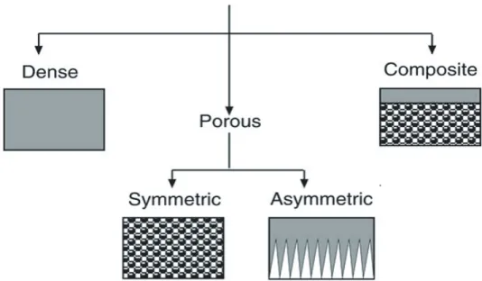
1.3.1 Definition and Classification
In all of the processes named in Fig. 1.1 membrane behaves as a selective barrier that allows the passage of certain components and retains in the mixture others. In essence, a membrane is nothing more than a discrete, thin interface that moderates the permeation of chemical species in contact with it. Since it has not a definite meaning, we could consider it as “any region that acts as a barrier between two fluids, restricting or allowing the flow of one or more components, or both fluids through it”. [21-22]. As this definition is somehow ambiguous, in the following paragraphs we will take into account different criteria to make a broad classification of mem-branes3, covering most of their characteristics.
Membranes can be classified according to different viewpoints [23]. The first clear-est distinction which could be used for a possible classification is their nature, i.e. biologi-cal or synthetic membranes. Along this work we will focus only on synthetic membranes (those which are synthetically created and intended for separation purposes in laboratory or in industry). Moreover, there are sub-classifications for synthetic membranes such as surface chemistry, bulk structure, morphology (form, structure and specific structural fea-tures) production method or other parameters.
These have been fully analysed in the literature [24-26], and next table (table 1.3)
summarizes, such classifications, focussing mainly on overview of material and structure. Basically this work is focused on UF and NF, especially on membranes that are poly-meric, porous, and asymmetric.
Synthetic membrane filters were developed by Richard Adolf Zsigmondy, Nobel Prize winner chemist, at the University of Göttingen [28], Germany, in 1927. They were first commercially by Sartorius® (now Sartorius-Stedim Biotech.) a few years later. They found immediate application in the field of microbiology and in particular in assessment of safe drinking water. In this sense, most important filters are microporous membranes (having microscopic pores). These are a thin porous film or hollow fiber having pores ranging from 0.01 to 10 µm, which are simplest of all the membranes in terms of principle of operation [27]. They are primarily found as symmetric porous membranes, having a uniform structure across the section of membrane.
This characteristic is used in MF filters by trapping the particles deep inside the structure of the membrane, on the order of 0.01 to 10 μm in diameter, all particles larger than the largest pores are completely rejected by the membrane; but, for that reason, they are eas-ily clogged.
3 Several precise and complete definitions of a membrane which cover all its aspect can be seen in several publications
Instead asymmetric membranes are made up of a thin surface layer supported (0.2-0.5 mm), on a much narrow, porous substructure (1-10 μm around).
table 1.3 Classification of synthetic membranes.
overview classification main Features
inorganic
Mainly ceramics and metal, they form an special class of microporous membranes, used in UF and MF applications for which solvent resistance and thermal stability are required.
material
organic
Polymeric membranes prepared under differ-ent membrane formation conditions and having a wide application range. (MF, UF, RO/NF), so that different pore sizes are produced.
porous Presenting a pore size distribution, filtration works as a conventional filter or sieve.
dense
Nonporous, dense film through which permeants are transported by diffusion under the driving force of a pressure, concentration, or electrical potential gradient.
homogeneous The composition of the membrane presents only one material.
heterogeneous Different materials by a superposition of layers, make up the membrane by superposition of lay-ers.
structure symmetric Structural and morphological properties do not depend on filtration layer. Uniform structure.
Asymmetric The structure of the membrane changes across it.Active layer and support skin are found. neutral It is electrically neutral.
charged It has electric fixed charges on the surface which can be positive or negatives ones. hydrophobic Membrane material repels water molecules.
hydrophilic Water molecules are attracted to membrane ma-terial.
Asymmetric membranes [28] are produced either by wet phase inversion from single polymers [29] or as composite structures. Therefore the separation properties and permeation rates are determinated exclusively by the top layer or active one (see Fig.1.3), while support layer functions as a mechanical support.
Figure 1.3: Membrane porosity of upper and lower parts of a membrane as imaged by SEM.
1.3.2 Membrane Module Design
The following section enumerates the principal module types, for industrial appli-cations of membrane separation processes. Membranes are installed in suitable devices, and these should be designed to operate with large membranes surface areas.
The design requirements of a particular separation, and the mechanism of trans-port through the membrane, will dictate and frequently limit, material choice, thickness, pore size, etc. Therefore, these limitations must be accommodated into an appropriate configuration and membrane module design to withstand the imposed conditions of op-eration [30-32].
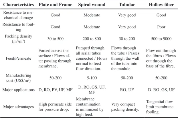
Membrane modules are available in four different designs of membrane; Spiral wound, Hollow fiber, Plate and framed and Tubular, whose main characteristics are sum-marized in table 1.4. In any case can be found many special modules for specific applica-tions which are described [29] in the literature.
Next figure (see Fig. 1.4), indicates the existing relationship in membrane mod-ules between the feed and permeate, all of them lead to complete mixing pattern between both the feed and permeate side of the membrane.
Flow pattern of membranes modules is usually related to the geometry and configuration, one of the most important points is if we apply dead-end filtration, where the feed stream is in plug flow, and the permeate flows in a normal direction away from membrane,
or cross flow filtration, then the feed or retentive side flows along and parallel to the up-stream of the mebrane, but the permeate fluids to the downup-stream side of the membrane, (see Fig. 1.5, for a clear scheme of both operation ways). In the case of tubular and hollow fiber, modules are characterised by tangential flow, and spiral wound have axial-annular flow pattern. There are other flow patterns as countercurrent flow, [33] where, both the feed stream and the permeate stream are in plug flow “countercurrent” to each other.
table 1.4 Main characteristics of membrane modules [30-32].
characteristics plate and Frame spiral wound tubular hollow fiber
Resistance to
me-chanical damage Good Moderate Very good Good
Resistance to
foul-ing Good Moderate Very good Poor
Packing density
(m2/m3) 30 to 500 200 to 800 30 to 200 500 to 9000
Feed/Permeate
Forced across the surface / Flows af-ter passing through membrane.
Pumped through all serial tubes connected / Flows normal to feed flow direction.
Flows through the tube / Passes through the wall of the tube into the module.
Flow out through the fibres / Flows out through the base of the fibre. Manufacturing
cost (US$/m2) 50-200 5-100 50-200 50-200
Major applications D, RO, PV, UF, MF D, RO, GS, UF, MF RO, UF D, RO, GS, UF
Major advantages High permeate side for pressure drop.
Membrane contamination is minimized by high feed.
Very compact packing density.
Tangential flow limit membrane fouling.
1.3.3 Membrane Material
There are more than 100 different materials, which have been used for membrane making as we can find in a fast review of the patents and scientific literature in the field,
[34-38], and furthermore, more and more materials are being added every year. Thus we can ask ourselves, which are the key factors for the development of new materials appli-cable for membrane production?
If we come back to the above definition of synthetic membrane, we focussed in two key factors, flux and selectivity, whose optimization should lead to more efficient membrane materials [39-40]. In any case, and due to the very different nature of these separations, the types of membrane materials used, and the methods of fabrication for such membranes, differ quite significantly.
Membrane material science has produced a wide range of materials of different structure and with different ways of functioning. Traditionally these materials can be clas-sified into three types [41]:
-Organic materials: including a vast number of polymers and elastomers, among which those based on cellulose had a significant role in the very beginning of Membrane. Tech.
-Inorganic materials: comprising many types of ceramic and metallic materials, and recently an increasing number of applications based on zeolites.
-Mixed or composite materials: normally membranes made of organic polymers which contain some inorganic material added or included during the synthesis process.
It is important to comment that a membrane material should ideally posses many of the following properties to be effective for separation [42].
-Appropriate chemical resistance. -Mechanical stability.
-Thermal stability. -High permeability.
All these membrane properties are obviously relative and they must be tested for selected individual processes, but some of the more usual polymers, are being used as base material for membranes tested in this work, so we will briefly discuss in the follow-ing paragraphs a few polymeric and inorganic membranes widely used for membrane separation processes.
early 1960’s, Loeb and Sourirajan published a method for making asymmetric cellulose acetate membranes with relatively high water fluxes and salt rejection, thus making RO and NF separations both possible and practical as required for a viable desalination proc-ess. Cellulose has a very high structural regularity and intermolecular hydrogen bonding, which makes cellulose difficult to dissolve due to the highest concentration of α-cellulose. For membrane applications they are used as derivatives of cellulose, example Nitrate (In-organic), Acetate, Triacetate (Organic) and mixed cellulose esters (Nitrocellulose) com-pounds. They are used for many laboratory applications including filters for sterilizing biological fluids, microbiology, contamination analysis and air monitoring.
Important advantages of Cellulose derivatives, are that they are available in a wide range of pore sizes from MF to RO, cast in sheets or as hollow fibers, suitable for aqueous and organic media, hydrophilic, mechanically stable and finally, they present, reasonably high porosity, providing superior flow rates, but rejecting low molecular weight contaminants poorly [41].
However, cellulose suffers from certain disadvantages also: narrow temperature range, low PH range and poor resistance to some alcohols4, which may oxidize the cellulose
membrane opening up the pores, and can be vulnerable to attack by bacteria and biologi-cal fouling.
Aromatic Polyamides (PA). Aromatic polyamide (AP, aramid) membranes were first developed by DuPont® in a hollow fiber configuration, but they can be found in sheet configuration too. Aramid membranes represent an important segment of a rapidly devel-oping technology for the separation of components of aqueous solutions, gaseous mix-tures and organic liquid mixmix-tures. They are highly inching crystalline polymers with bet-ter thermal stability and higher resistance to solvents than do their aliphatic counbet-terparts such as Nylon. By this way Polyamide membranes have better resistance to hydrolysis and biological attack than do cellulosic membranes. Aromatic Polyamides has been form for many years in the field of RO membranes. In this case, the polymer forms the active layer showing high salt rejection, high water permeability and high fouling tolerance,
[44]. Among their other applications, these membranes are used in waste-water treatment, desalination of sea water and dialysis.
Poly(Ether)Sulfone (PES). It is a heat-resistant, transparent, amber coloured, non-crystalline polymer having the molecular structure shown in Fig. 1.6. Properties of PES are: it remains in satisfactory condition after long-term continuous use without causing any dimensional change or physical deterioration; it has by far better high temperature properties than conventional polymers (it resists temperatures as high as 200ºC); it has wide pH tolerance (1 to 10), fairly good chemical liquids resistance and high degree of molecular immobility, rigidity or creep resistance. Thus this type of material is among the most used in Membrane Technology.
PS and PES membranes can be found in a wide range of pore sizes, ranging from 10 Å to 0.2 μm; then PES filters can be used in modules covering MF/UF/NF. These membranes5
provide removal of fine particles, bacteria, viruses, and fungi; making it a versatile mem-brane for applications such as sample preparation, sterile filtration, Hemodialysis (H), waste water recovery, food and beverage processing, and Gas Separation (GS).
Regarding membrane configuration they are utilized in both flat sheet and hollow fibres in UF and MF processes. They are also used as porous supports, in thin film composite
membranes for RO desalination, offering extremely high flow rates at very low differen-tial pressures when compared with Nylon or PolyPropylene (PP) media [45-46].
The most serious disadvantage it posses, consists in the fact that they often present a pow-erful nonspecific adsorption capacity. This phenomenon, usually known as fouling, leads to a rapid deterioration of the membrane permeability.
PolyTetraFluoroEthylene (PTFE). Also known as Teflon®, the trade name given by Dupont®, may be visualized as Polyethylene with all its hydrogen atoms substituted by fluorine.
Among its advantages we can mention that is very stable to strong acids, alkalis and sol-vents, it permits to a very wide range of temperature, being also very hydrophobic. Other interesting application related with PTFE is the commercial membrane GoreTex® (see
Fig. 1.7). This makes use of the high hydrophobicity of the membrane material so water (in liquid form) cannot pass through the membrane, while water vapour transport is al-lowed [46]. PTFE membranes find many uses in the treatment of organic feed solutions, vapours and gases.
PolyCarbonate (PC). It is a class of polyesters derived from carbonic acid and bisphenol-A. They are prepared in the form of thin dense films (approximately 10 mi-crons thick) of high molecular weight, being used as the most common substrate for the preparation of microporous track etched membranes. In this fabrication method, they can be obtained porous MF membranes, with very narrow pore-size distribution (see Fig. 1.8)
whose pore shape corresponds to extremely uniform cylindrical or slightly conic pores in a flat configuration. Due to these unique characteristics, these membranes have been used as model pores in fundamental studies of membrane transport phenomena [47].
PC membranes having hydrophilic behaviour, are available in a range of pore sizes from 0.01μm to 12 μm, then mainly cover MF; they are resistant to most organic solvents, having an excellent chemical resistance, good thermal stability, non-hygroscopic and ex-tremely weight stable.
PolyPropylene (PP). It is produced by the polymerization of propylene using well known Ziegler-Natta catalyst [48]. It is usually available in the form of hollow fibres, but it is presented in flat disc filters too, being flexible, durable and virtually indestructible. Significant properties are: hydrophobic, relatively inert, compatible with organic solvents,
making them highly suitable for High Performance Liquid Chromatography (HPLC), and can withstand moderately high temperatures.
Main applications includes their use as a separator in batteries, allowing ion migration across the membrane, oil mill and refinery industry, metallurgy industry food and phar-maceutical processes; these membranes usually have a mean pore size between 0.1μm and 20 μm.
PolyAcryloNitrile (PAN). It is another commercially available material based on free radical polymerization of AcryloNitrile (AN), [49], which has been widely applied in the preparation of separation membranes, due to its superior resistance to hydrolysis and oxidation. These membranes have received much attention in the fields of water treat-ment, PerVaporation (PV) and supports for other (bio-)macromolecules. Main application has been extensively UF, but it has been used as a support for NF and RO, [51-52].
Inorganic membrane materials. The application of polymer membranes is gener-ally limited to temperatures below about 200°C and to the separation of mixtures that are chemically inert. Most inorganic membrane, known as ceramics membranes, are materi-als having much better selectivity and permeability at high temperatures than polymeric membranes at low temperature. They are also much more resistant to chemical attack and to corrosive liquids and gases. The wide variety of materials that may be used in the fab-rication of the inorganic membranes, covers from ceramic membranes to other inorganic compounds. The most common membranes are made of Al, Si. Ti, Zr6 oxides or are
estab-lished by adding some additional compounds present in minor concentration. Nowadays, inorganic materials compete successfully with polymers for commercial use.
Ceramic membranes are a type of inorganic materials such as alumina, titania, zirconia oxides or some glassy materials. They are available from several manufacturers in differ-ent shapes, mainly tubular and hexagonal, and with various channel diameters (see Fig. 1.9); they are manufactured by a number of methods, these include particle dispersion and slip casting, phase separation and leaching, anodic oxidation, thin film deposition, and so on [50]. These membranes offers sufficiently high permeability and selectivity for the
6 Some zirconia tubular membranes were studied during this work, as shown in paper four.
targeted mixture and can be made into the membrane module for practical applications. They normally have an asymmetrical structure composed of at least two, but mostly three, different porosity levels. Indeed, before applying the active, microporous top layer, a mesoporous intermediate layer is often applied in or-der to reduce the surface roughness.
Main applications are: air separation by mixed oxy-gen ionic, electronic conducting ceramic and molecu-lar sieve carbon membranes, hydrogen separation by metal, silica and zeolite, proton-conducting ceramic membranes, hydrocarbon separation by zeolite and silica membranes, and carbon dioxide separation by silica or zeolite membranes.
Other important materials [50] not summarized in previous paragraphs are also used as a membrane material, next table (table 1.5) summarizes principal properties and applications of more common membrane materials.
table 1.5 Some characteristics of main membrane process and materials used
membrane type membrane structure preparation Applications
Asymmetric CA, CN, PA,
PS, PES, PAN. Homogeneus or microporous “skin” on a microporous substructure. Casting and precipita-tion. UF, RO, MF, GS, PV
Composite CA, PA, PS, PI. Homogeneous polymer filmon a microporous substructure. Deposition on micropo-rous substructure. RO, GS, PV
Homogenous S. Homogeneous polymer film. Extrusion. GS
Ion exchange DVB, PTFE. Homogenous or microporous co-polymer film, positively
or negatively charged ions. Immersion or ion exchange. ED Microporous: Sintered
polymer PTFE, PE, PP. 0.1 to 20 μm pore diameter. Moulding and sintering. Leaching. Filtration (F) Microporous: Ceramic,
metal glass. 0.05 to 20 μm pore diameter.10 to 100 μm pore diameter. Moulding and sintering. Leaching. GS, F (molecular mixtures) Microporous: Sintered
polymer PTFE, PE, PP. 0.1 to 5 μm diameter. Stretching a partial crystalline film. F (air, organic sol-vents) Microporous: Track-etched
PC, PEsT. 0.02 to 20 μm pore diameter. Irradiation and acid leaching. F (suspensions, ster-ile filtration) Symmetric microporous
phase inversion CA. 0.1 to 10 μm pore diameter. Casting and precipita-tion. Sterile filtration, water purification, dialysis
CA - Cellulose acetate. CN - Cellulose nitrate. CTA - Cellulose triacetate. DVB - Divinylbenzene. PA - Polya-mide. PAN - Polyacrylonitrile. PC - Polycarbonate. PE - Polyethylene. PES - Polyethersulfon. PEsT - Polyester. PI - Polyimide. PP - Polypropylene. PS - Polysulfone. PTFE - Polytetrafluoroethylene. PVC - Polyvinylchloride. PVDF- Polyvinylidene fluoride. S - Silicon rubber.
ED - Electrodyalisis. F - Filtration. GS - Gas separation. MF - Microfiltration. PV - Pervaporation. RO - Reverse Osmosis. UF - Ultrafiltration.
1.4 membrAne processes
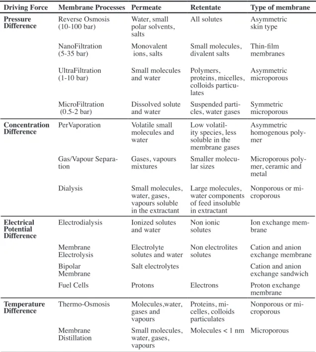
In last previous pages, several types of membrane processes have been mentioned. In some more detail, they can be classified into several groups according to the driving force that causes the permeant flow across the membrane, such as:
-pressure difference -concentration difference -temperature difference -electrical potential difference
In the major part of membrane separation processes, the driving force is a pres-sure difference or a concentration difference across the membrane and it operates mainly by two basic processes: the first one is filtration, in which a fluid flows through pores in the membrane material that holds back those components of the feed that are above a certain size, being this size limit determined by average particle size in micrometers (or nanometers) or which is equivalent, by molecular weight; the second one is diffusion, in which components from the feed material pass through the non-porous membrane moving across the own membrane material, which holds back some or all the fluid.
1.4.1 Pressure Driven Membrane Processes
The Pressure driven processes are the technically and commercially most relevant membrane process. They work creating a pressure drop across the membrane which acts as driving force and whose magnitude depends on the size of particles to be separated/ retained. In operational terms, the processes involved are7:
-reverse osmosis (ro) -nanoFiltration (nF) -ultraFiltration (uF) -microFiltration (mF)
1.4.2 Concentration Gradient Driven Processes
This term is often related to the concept of diffusion or the migration of a sub-stance across the membrane due to a concentration gradient.
Then, if a concentration gradient of permeating molecules is established in both sides of the membrane, simple statistics laws show that a net transport of matter will occur from the high concentration to the low concentration region. This concept was first recognized, theoretically and experimentally, by Fick in 1855 [53]. Fick formulated his results as the equation now called Fick’s law of diffusion.
7 These are listed in the order of descending operating pressure, or decreasing effectiveness in terms of the fineness of the separation achieved.
J D
x c
i i i
2 2
Where the proportionality factor Di is called the diffusion coefficient (cm2/s), being Ji the
flux of component i (g/cm2·s ) and c
i the concentration of component i (gr/cm3). Diffusion
coefficient is a measure of the mobility of the individual molecules.
Diffusion is an inherently slow process. In practical diffusion-controlled separa-tion processes, useful fluxes across the membrane are achieved by making the membranes very thin and creating large concentration gradients in the membrane. Most important process included in this section are:
-pervaporation (pv) -gas separation (gs) -vapour permeation (vp) -dialysis (d)
1.4.3 Electrical Potential Driven Membrane Processes
In these processes, an electrical potential difference act as the driving force using the ability of charged ions or molecules to conduct an electrical current. If an electrical potential difference is applied to a salt solution, the positive ions (the cations) migrate to the negative electrode (the catode). If molecules are uncharged, there is not driving force but also polar molecules can lead to selective transport under electrical potential applied. This transport of ions across an ionic membrane is based on the Donnan exclusion mecha-nism, [54], but if now we considered an electrical potential difference and electrically charged membranes it can be used in various arrangements, such as:
-electrodialysis (ed)
-membrane electrolysis (me) -bipolar membrane (bm) -Fuel cells (Fc)
In all cases the charged membrane constitutes a selective barrier where ions are either repelled or transported dependent on the ionic and membrane relative charge.
1.4.4 Temperature Gradient Driven Membrane Processes
Mainly emphasize on Thermo-osmosis or Thermo diffusion, which is a process where a porous or nonporous membrane separates two phases having a temperature gradi-ent between them [55].Then a volume flux exists from the warm side to the cold side until thermodynamics equilibrium is attained. Main temperature driven processes are:
-thermo-osmosis (to) -membrane distillation (md)
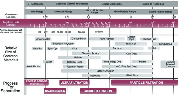
Completing this section, there are other membrane processes such as facilitated or carry mediated membrane transport, liquid membrane separation, membrane contactors, membrane reactors, ect, in which membrane separation is combined with conventional processes. Finally the next “filtration chart” (see Fig. 1.10) illustrates the various particle sizes as well as the filtration methods [56] that can deal with each range of particle size and characterization methods.
driving Force membrane processes permeate retentate type of membrane
pressure
difference Reverse Osmosis(10-100 bar) Water, small polar solvents, salts
All solutes Asymmetric skin type
NanoFiltration
(5-35 bar) Monovalent ions, salts Small molecules, divalent salts Thin-film membranes UltraFiltration
(1-10 bar) Small molecules and water Polymers,proteins, micelles, colloids particu-lates
Asymmetric microporous
MicroFiltration
(0.5-2 bar) Dissolved solute and water Suspended parti-cles, water gases Symmetric microporous
concentration
difference PerVaporation Volatile small molecules and water
Low volatil-ity species, less soluble in the membrane gases
Asymmetric homogenous poly-mer
Gas/Vapour
Separa-tion Gases, vapours mixtures Smaller molecu-lar sizes Microporous poly-mer, ceramic and metal
Dialysis Small molecules, water, gases, vapours soluble in the extractant
Large molecules, water components of feed insoluble in extractant
Nonporous or mi-croporous
electrical potential difference
Electrodialysis Ionized solutes
and water Non ionic solutes Ion exchange mem-brane Membrane
Electrolysis Electrolyte solutes and water Non electrolites solutes Cation and anion exchange membrane Bipolar
Membrane Salt electrolytes Cation and anion exchange sandwich
Fuel Cells Protons Electrons Proton exchange
membrane
temperature
difference Thermo-Osmosis Molecules,water, gases and
vapours
Proteins, mi-celles, colloids particulates
Nonporous or mi-croporous
Membrane
Distillation Small molecules, water, gases, vapours
Molecules < 1 nm Microporous
1.5 chArActeriZAtion oF membrAnes
Characterization is a way of relating structural and morphological information coming from a particular class of membrane to the use it will have in a particular appli-cation. The term characterization refers to knowledge of the constitution, structure and functional behavior of the membrane [56]. This knowledge needs to be acquired by using appropriate methods, because the studied membranes are put into a large number of dif-ferent uses even within a particular separation process, then a membrane will be charac-terized in terms of its pore size, Molecular Weight Cut-Off, porosity, thickness, symmetry, permeability, hydrophobicity and hydrophilicity, adsorption, crystallization, etc.
In other words, we can see that a complete characterization should include both the functional aspects of the problem and not less important, the structural ones. In a first view, functional and structural characterisation methods apply uniformly into two broad areas, porous media and non-porous media [57].
In this sense structural characterization is essentially the determination of as much as pos-sible from the following experimental parameters:
Pore Size. The pore size of a membrane gives an indication of the mean size of the pores present on a membrane. It is also correlated with the particle size that the mem-branes will be able to reject, so characterizing the membrane retention capabilities. The pore size of a membrane can range from 1000 to 0.0001 microns, covering the four main types of membranes, MicroFiltration (MF), UltraFiltration (UF), NanoFiltrations (NF) and Reverse Osmosis (RO). In UF, the pore size diameter quoted is usually an average value8, but to confuse the issue, the value quoted in MF is usually defined in terms of the
8 UF, NF and RO membrane manufacturers frequently characterize their membranes using the “cutoff” concept rather than pore size.
largest particle able to penetrate the membrane. This nominal pore diameter can be 5 to 10 times smaller than the apparent pore diameter based on direct microscopic examination of the membrane. Membrane pores tend to be highly non-uniform, so then any assumption on shape and inner pore conformation is solely for the purpose of mathematical modelling and interpretation. However they can give accurate descriptions and quantitative analysis of how a membrane will behave in certain situations. Pore size is determined by bubble point analysis (only the biggest pore size), porosimetry (Gas-Liquid for MF or liquid-liquid for UF, while mercury porosimetry is usually intended for ceramic membranes), or microscopic analysis, with some other not so used methods also able to give information about pore sizes. However, the pore size measured gives not an absolute measure because the membrane pores are interconnected (net worked) instead of cylindrical through out capillaries.
Pore size distribution. It gives a quantitative description of the range of pore sizes present in the membrane sample. Obviously, any method giving a complete description of the whole pore size distribution, can be used to determinate the mean, maximum or mini-mum pore size present in the sample. It provides a more complete description of range of pores you will find in that membrane, but also this so exhaustive information makes more difficult to asses the particle sizes likely to be retained by the membrane.
Porosity (θ). The porosity is the pore volume divided by the volume of the raw material.If we note as: Vm=Vt-Ve, the solid volume material of the sample (being Ve is the empty volume or volume of the pores), whereas Vtis its geometrical or total volume, the porosity is given by the following equation.
Porosity can be also given in terms of surface areas, supposed cylindrical shaped pores, since: Vt =At∆ x , with ∆x the thickness of the membrane or active layer. Surface poros-ity can be measured by analysing processed images obtained from microscopic analyses such as scanning electron microscopy (SEM), transmission electron microscopy (TEM), or atomic force microscopy (AFM).
Pore density: related with previous parameter, we can define the density of pores as the number of them present in the surface of the membrane, per unit of surface area.
Surface roughness. It could be defined as the deviation of the actual membrane surface topography from an ideal atomically smooth surface.
Tortuosity (ψ). It reflects the length of the aver-age pore compared to the membrane thickness (See Fig. 1.11). Simple cylindrical pores crossing the membrane normally to the surface have a unity value of tortuosity, that is, the average length of the
V V
1 t m
i= - Eq 2
pore matches with the membrane thickness. Usually pores take a more meandering path through the membrane, so typical tortuosities are in the range [1.5, 2.5].
On the other hand, regarding the membrane/effluent coupling or functional param-eters, then related with the membrane permeation (those specifically defined to character-ize membrane as filter materials); the following are a brief summary of several commonly analysed parameters in a functional characterization.
Molecular Weight Cut-Off. The nominal molecular weight cutoff (MWCO) is a performance-related parameter, defined as the value of a given solute molecular weight for which the rejection is 90%, (see Fig. 1.12).This method is based on steric or size based rejection of solutes by a membrane [58]. Typically, a mixture of water soluble molecules and/or macromolecules is made and presented as the feed to the membrane. In the case of UF and MF, the macromolecule solution can be a mixture of proteins, or a polydisperse solution of a single hydrophilic polymer such as dex-trans, polyethylene glycols or others. As the MWCO decreases, the mean pore diameter for the membranes has been found to decrease [59]. Really MWCO is only a rough indication of the membrane ability to remove a given compound given that molecular shape, polarity, and membrane-solute interaction strongly affect rejection
[60]. Moreover, membrane surface characteristics (surface porosity and pore size distribution) may influence the apparent size of particles retained. There is currently no universally accepted industrial standardard for the determination of MWCO and values presented are hardly comparable amongst different manufacturers.
Hydraulic Permeability. In 1856, Darcy observed that the rate of flow of water through a permeable layer of thickness ∆x could be related to the driving pressure ∆P by the simple expression:
Last equation can be described in terms of hydrodynamic resistance for the filtration of solvent molecules (water), through the membrane, in this sense the permeate flux changes with the mean transmembrane pressure as:
P
J
Adt
V
wR
mw
3
3h
==
Figure 1.12: Solute rejection versus molecular weight.
P
L
wJ
w3