Describing, Instantiating and Evaluating a Reference Architecture: A
Case Study
Paris Avgeriou
University of Cyprus Department of Computer Science
75 Kallipoleos Str., P.O. Box 20537CY-1678 Nicosia, Cyprus Email: [email protected]
Abstract. The result of a domain maturing is the emergenceof reference architectures that offer numerous advantages to software architects and other stakeholders. However there is no straightforward way to describe a reference architecture and in sequence to design in-stances for specific systems, while at the same time assuring the quality of the end product. This paper presents an approach of describing a reference architecture, instantiating it into a software architecture by making implementation decisions and evaluating it with respect to quality attributes. A case study for the approach is drawn from the domain of Learning Management Systems which is maturing and would greatly benefit from a reference archi-tecture. This work is based upon the IEEE standard for architectural description, on well-established software engineering practices, and on the empirical results of designing, devel-oping and evaluating Learning Management Systems.
Keywords: software architecture, reference architecture, architectural design, Learning Management Systems, quality attributes, evaluation of software architecture.
1
Introduction
ar-chitecture and also increments it by adding details that are particular to the specific implementation.
There are three issues that arise from the above:
• How should we describe reference architectures? Should we use the same techniques as in the description of software architectures, and if so, which ones?
• How should we generate instances of the reference architecture for spe-cific implementations? What should we change and what should we add in the description of the reference architecture in order to come up with one of its instances?
• How do we know that we have designed a high-quality reference archi-tecture? How do we know that the implementations of the reference ar-chitecture will satisfy certain desirable qualities?
This paper proposes an approach to tackle these issues. It proposes a description for reference architectures, demonstrates how the latter can be instantiated into a soft-ware architecture instance, and suggests an evaluation framework for the assessment of the reference architecture with respect to quality attributes. The description of the refer-ence architecture and its instances is based on a combination of the IEEE 1471-2000 Recommended Practice for Architectural Description of Software-Intensive Systems [15], and the widely-adopted Rational Unified Process [20, 21, 24]. In particular, the de-scription conforms to the IEEE standard, but also utilizes some concepts from the RUP such as the views, the implementation decisions, architectural patterns etc. As far as the description of an architectural instance, this is performed by showing the differences be-tween the two descriptions and elaborating on the extra elements contained in the de-scription of the instance. Finally the evaluation framework is based on well-established software engineering techniques that regard quality evaluation of architectures.
The structure of the paper is as follows: Section 2 deals with the description of the reference architecture per se and Section 3 describes a software architecture instance with its corresponding architectural prototype. Section 4 introduces a brief discussion about the evaluation of this approach. Finally, Section 5 contains conclusions about the added value of our approach and future plans.
2
The Reference Architecture
2.1
About the architectural description
The description of the reference architecture and its derived instances is based on three facets:
¾ It adopts the format of the IEEE 1471-2000 Recommended Practice for Architec-tural Description of Software-Intensive Systems [15]. This standard dictates that the first step in designing a software architecture is to explicitly define the
stake-holders of a system under development and any concerns that they may have with
respect to any possible aspect of the system. The description of the architecture per se is organized into different views, where each view addresses one or more of the stakeholders’ concerns. Also each view conforms to a viewpoint, in the sense that a viewpoint determines the conventions, according to which a view is created, illus-trated and analyzed. Therefore viewpoints need to be defined, before we can start designing diagrams for each view.
¾ It adopts and customizes a big part of the Rational Unified Process (RUP), a well-established, software engineering process [20, 21]. The RUP proposes certain ele-ments that should be contained in an architectural description, such as a specific set of views, architectural patterns, desirable quality attributes, implementation con-straints (e.g. development and run-time platform, legacy code, third-party software). It is also noted that Rational Unified Process considers only the use case view and the logical view as mandatory in the architectural design while all the rest are op-tional.
¾ It uses the widely-adopted Unified Modeling Language [7, 25], which is a de facto standard in the software industry, to design the diagrams of the architectural views.
This approach combines the above, and proposes that a descriptionof a software
architecture should contain the following:
The system stakeholders, and the concerns that they may have regarding any possible aspect of the system.
The definition of the viewpoints that will address the stakeholders’ concerns, and pre-scribe the methodology used and the contents of corresponding views.
The views (i.e. the most important or architecturally significant modeling elements) of the models described in the RUP (use case model, analysis model, design model,
ployment model, implementation model). These views must conform to the previ-ously defined viewpoints.
The architectural patterns that characterize parts of the architecture.
The quality attributes that are desirable for the system and must be supported by the architecture. The requirements might or might not be described by use cases.
A brief description of the implementation constraints, i.e. the platform, the legacy sys-tems and the third-party software.
Other issues that are of particular importance to the specific system being designed. For the case of Learning Management Systems an extremely significant issue is the
adoption of international Learning Technology standards that should be adopted and
implemented into systems, in order to achieve the quality of interoperability.
Consequently, all these constituents should be included in the description of the software architecture instances. As far as the description of the reference architecture, this should remain at an abstract level, and details that concern particular implementa-tions must be left out. Such details are:
The views that concern the system implementation and in particular the implementa-tion view and the data view.
The implementation decisions (platform, legacy systems, third-party software etc.). The collection of all these elements for the reference architecture is quite volu-minous, and can’t be included in this paper for practical reasons. Instead, a summarized version for all the elements will be provided and a suggestive diagram in each view. A full description of the reference architecture can be found in [5], while a description of a software architecture instance that derives from the reference architecture can be found in [4].
2.2
Identification of stakeholders and concerns
The system stakeholders are either individuals, groups, or organizations, that have interests or concerns about the system being developed. Every system has several such stakeholders that deeply affect its design and development [6]. The stakeholders considered in this architectural description are the following:
a) Users of the system, which include students, professors, administrative staff of the educational institute, teaching assistants, courseware authors, system administrators.
b) Acquirers of the system, which include universities or in general higher educational institutions, K-12 educational institutions, and companies or organizations that perform employee training.
Every stakeholder has certain concerns with respect to the system being devel-oped, i.e. issues about the development, operation, function or any other system aspect that is of relevance to a particular stakeholder. The concerns identified in this architec-tural description are the following:
(a) What is the purpose or missions of the system?
(b) What is the appropriateness of the system for use in fulfilling its missions? (c) What is the feasibility of constructing the system?
(d) What are the risks of system development and operation to users, acquirers, and developers of the system?
(e) What are the quality attributes that the system must support? (f) Who are the external actors that interact with the system?
(g) What are the tasks or functionalities that the system offers to those external ac-tors?
(h) What is the modularity of these tasks?
(i) What are the computational elements of a system and the organization of those elements?
(j) What are their interfaces? (k) How do they interconnect?
(l) What are the mechanisms for interconnection? (m) How do they dynamically interact?
(n) What is the system topology with respect to computational nodes?
(o) What are the protocols used for communication between the physical nodes? (p) How are the components distributed among the physical nodes?
(q) What are the implementation level components and how are they layered? (r) What are the data stored in the system?
(s) How are the data stored in the system (XML, file system, Data Base)?
2.3
Definition of the viewpoints
A viewpoint specifies the conventions, with which a view is created, depicted in diagrams and analyzed. In this sense a view conforms to a viewpoint. The viewpoints in specific, determine the language used for the description of the view and any other modeling method or technical analysis applied for the representation of the correspond-ing views. The choice of viewpoints that follows is based on the specification of stake-holders and concerns, presented in the previous sub-section.
2.3.1 The Use-Case Viewpoint
This view addresses three types of stakeholders: users, acquirers, and developers and re-fers to concerns (a), (b), (c), (d), (e), (f), (g) and (h). The constructed views shall use the
Unified Modeling Language [7, 25] as a modeling language and especially use-case dia-grams. They shall also use the modeling techniques, specified in the Rational Unified Process. Specifically they will present a subset of the Use-Case Model, presenting the architecturally significant use-cases of the system. They will describe the set of scenar-ios and/or use cases that represent some significant, central functionality, as seen from external actors. They will also describe the set of scenarios and/or use cases that have a substantial architectural coverage (that exercise many architectural elements) or that stress or illustrate a specific, delicate point of the architecture.
This viewpoint is selected because it shows how the system interacts with the external environment that it inhabits in.
2.3.2 The Logical Viewpoint
This view addresses two types of stakeholders: developers, maintainers and deals with concerns (i), (j), (k), (l), and (m). The constructed views shall use the Unified Modeling Language [7, 25] as a modeling language and especially Sequence, State, Collaboration, Activity, Class, and Object diagrams. They shall also use the modeling techniques, specified in the Rational Unified Process. Specifically they will present a subset of the Design Model which presents architecturally significant design elements. They shall de-scribe the most important classes, their organization in packages and subsystems, and the organization of these packages and subsystems into layers. They shall also describe the most important use-case realizations, for example, the dynamic aspects of the archi-tecture.
This viewpoint is selected because it shows the decomposition and behavior of the sys-tem in a logical level of abstraction.
2.3.3 The Deployment Viewpoint
The stakeholders to be addressed by the viewpoint, are the developers and maintain-ers, while the corresponding concerns are (n), (o), and (p).
The constructed views shall use the Unified Modeling Language [7, 25] as a modeling language and especially deployment diagrams. They shall also use the modeling tech-niques, specified in the Rational Unified Process. Specifically they will present the Deployment Model which presents the physical nodes and the interconnection be-tween them. They will describe one or more physical network (hardware) configura-tions on which the software is deployed and run.
2.3.4 The Implementation Viewpoint
The stakeholders to be addressed by the viewpoint are developers, maintainers and the only concern addressed is (q). The constructed views shall use the Unified Modeling Language [7, 25] as a modeling language and especially component diagrams. They shall also use the modeling techniques, specified in the Rational Unified Process. Spe-cifically they will present the decomposition of the software into layers and subsystems in the implementation model. They will describe an overview of the implementation model and its organization in terms of the components in implementation subsystems and layers, as well as the allocation of packages and classes (from the Logical View) to the implementation subsystems and components of the Implementation View.
This viewpoint is selected because it shows the artifacts of code that comprise the sys-tem.
2.3.5 The Data Viewpoint
The stakeholders to be addressed by the viewpoint are developers, maintainers and the concerns tackled are (r) and (s). The constructed views shall use the Entity-Relationship Diagrams which is the standard notation for relational databases. Specifi-cally they will present the architecturally significant persistent elements in the data model. They will describe an overview of the data model and its organization in terms of the tables, views, indexes, triggers and stored procedures used to provide persistence to the system. They will also describe the mapping of persistent classes (from the Logi-cal View) to the data structure of the database.
This viewpoint is selected because it shows the persistent data that are stored and ma-nipulated by the system.
2.4 The
views
2.4.1 The use-case view
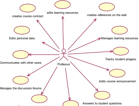
The elements from this view have been extracted from a business model, which is described in [1] and is based on the IEEE LTSC standard for Learning Technology Systems Architectures [13]. As an example, depicts the use cases initiated by a
professor. Figure 1
creates course contract
edits learning resources
creates references on the web
Manages learning resources
Tracks student progess
Adds course announcement
Answers to student questions
Reviews evaluation data Communicates with other users
Edits personal data
Manages student working groups Manages the discussion forums
Professor
Figure 1 – Use cases initiated by a professor
2.4.2 The logical view
ex-amples of this kind of architectural style are layered communication protocols such as the ISO/OSI, or operating systems such as some of the X Window System protocols.
The RUP utilizes the aforementioned architectural pattern by defining four lay-ers in order to organize the subsystems in the design model. According to the RUP, a
layer is a set of subsystems that share the same degree of generality and interface
vola-tility. The four layers used to describe the architectural structure of a software system are [20]:
Application-specific: A layer enclosing the subsystems that are application-specific,
in our case, specific to LMS and are not meant to be reused in different applications. This is the top layer, so its subsystems are not shared by the subsystems of other lay-ers.
Application-general: A layer comprised of the subsystems that are not specific to a
single application, such as an LMS, but can be re-used for many different applications within the same domain or business.
Middleware: A layer offering reusable building blocks (packages or subsystems) for
utility frameworks and platform-independent services for things like distributed ob-ject computing and interoperability in heterogeneous environments, e.g. Obob-ject Re-quest Brokers, platform-neutral frameworks for creating GUIs.
System software: A layer containing the software for the computing and networking
infrastructure, such as operating systems, DBMS, interface to specific hardware, e.g. TCP/IP.
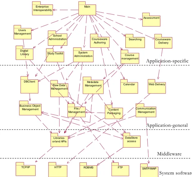
The proposed layered architecture for a Learning Management System is de-picted in Figure 2, which is a first-level decomposition in the design model. This dia-gram, besides identifying all first-level subsystems and organizing them into layers, also defines dependencies between them, which are realized through well-specified inter-faces. This list of first-level subsystems has been produced by a list of patterns de-scribed in [3].
Enterprise Interoperability
Main
Users Management
Admi ni stratio n
management
Business Object
Management File Management
Me tadata Management
Content Packaging
Communication Management
Web Delivery
TCP/IP
Calendar Raw Data
Management
RDBMS
DataStore access DBClient
FTP SMTP/IMAP HTTP
Libraries or/and APIs Study Toolkit
School
Administration Courseware Authoring
System
Course Searching
Assessment
Courseware Delivery
Digital Library
Application-specific
Application-general
Middleware
System software
Figure 2. The layered architecture of the component-based Learning Management Sys-tem
2.4.3 The deployment view
Web Server
RDBMS
Application Server
Client Persistent Objects
Server
Printer PCL/PS ODBC
Chat server
WhiteBoard
Server serverLOM HTTP
Mail server
FTP server
Conferencing server
RPC HTTP
ODBC
RPC RPC RPC IMAP/POP FTP
T.120 / H.323
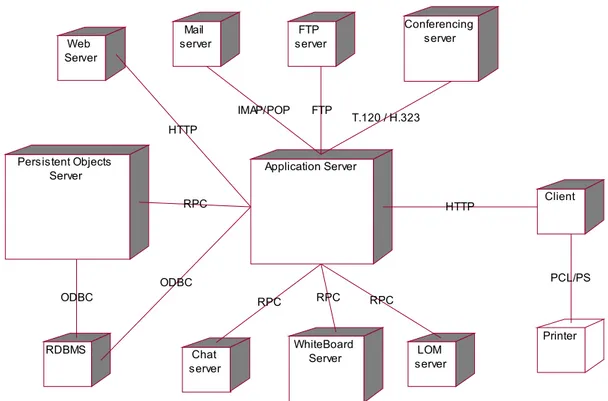
Figure 3 The deployment diagram
The deployment diagram in Figure 3 depicts all the system servers that are con-nected to the application server through appropriate protocols. The application server is assigned with all the components that do not belong to the other servers, and acts like the ‘glue’ between all the other parts.
This deployment diagram is part of the reference architecture and therefore is meant to be as generic as possible. Therefore all the servers have been placed in differ-ent computational nodes. However in software architecture instances derived from the reference architecture, this topology is expected to change in the sense that more than one servers will be placed in the same computational node.
2.5 Architectural
patterns
The architectural patterns that have been used, as seen in the catalogue com-posed in [6, 9, 26] include: the layered style as aforementioned; the Client-Server style in several components and especially in the communication management components
(e.g. e-mail, chat); the Model-View-Controller style in the Graphical User Interface de-sign; the blackboard style in the mechanisms that access the database in various ways;
the event systems style for notification of GUI components about the change of state of
persistent objects.
2.6
Qualities supported by the architecture
Another significant concern that needs to be addressed in this architectural de-scription is the choice of desirable qualities for LMS, selected from the list of qualities described in [6]. The complete evaluation of the reference architecture can be found in [2, 5], but in this subsection, it will suffice to mention the quality attributes that are important for this specific category of systems and therefore should be supported by the reference architecture.
The quality attributes that are of paramount importance for Learning Manage-ment Systems are interoperability, modifiability, portability, usability, reusability
and integrability. LMS are required to interoperate with each other or other systems so that they can exchange student records, learning resources and their metadata, as-sessment tests and so on. They need to be easily modifiable and extensible, so that they can be adapted to emerging technologies and pedagogical models and thus increase their lifetime. They need to be portable to multiple clients, so that their users can operate them through a web interface, independently of the client platform. They must be us-able, because students must concentrate on learning processes rather than being cogni-tively overloaded by a dysfunctional user interface. They must be able to be constructed by integrating existing components, and reversely they should be able to offer their components to be reused in future applications. On the other hand, other qualities like
security and availability are given lower priority, since LMS are not ‘mission-critical’ applications and thus need not be highly secure or continuously up and running.
2.7 Standards
Adoption
This reference architecture emphasizes, as aforementioned, on the adoption of international Learning Technology standards, in order to achieve interoperability which is currently a major issue in the domain of LMS [2, 27]. In particular the goal is to map particular standards to individual components of the architecture, in order to provide a guide of standards adoption and implementation to LMS vendors. This is meaningful and useful since Learning Technology standards are still quite at an immature level and there exists much confusion about the nature and application of each standard.
depicts the mapping of standards to individual components of the reference architecture. It is noted that a single component may implement more than one standards. For exam-ple, the Courseware Delivery Component may implement the IMS Content Packaging
Table 1 – Mapping between LT standards and architectural components
Component Standard
All components (Business
model) IEEE LTSC LTSA
IMS Learner Information Package School Interoperability Framework School Administration
IMS Reusable Competency Defini-tion
Enterprise Interoperability IMS Enterprise
Assessment IMS QTI
Searching and Metadata
man-agement IEEE LTSC LOM
IEEE LTSC Computer Managed Instruction
IMS Content Packaging
IEEE LTSC Digital Rights Expres-sion Language
IMS Simple Sequencing Courseware delivery
ADL SCORM
Study toolkit IMS Learning design, EML Content packaging IMS Content Packaging
3
A Software Architecture Instance
The reference architecture presented in the previous section does not delve into specific implementation details. This matter will be dealt with in software architectures that will be instances of the reference architecture and will refine and extend the con-cepts defined in the reference architecture. Such a software architecture instance was designed for the development of a prototype Learning Management System, called ‘Athena’, as described in [4]. This particular instance has employed Java as an imple-mentation platform. The full description of the software architecture instance cannot be elaborated here but it will suffice to discuss the differences between the reference archi-tecture and the software archiarchi-tecture instance for the ‘Athena’ LMS, as illustrated in
. In the next subsections, these differences will be outlined and the architectural prototype will be briefly introduced.
Table 2
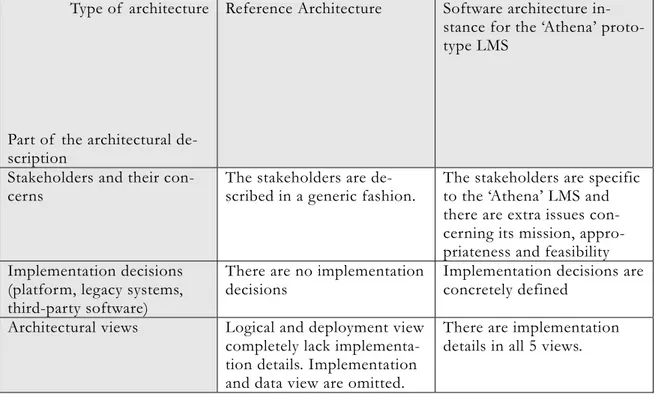
Table 2 – The differences between the reference architecture and the software architec-ture instance for the ‘Athena’ LMS
Type of architecture
Part of the architectural de-scription
Reference Architecture Software architecture in-stance for the ‘Athena’ proto-type LMS
Stakeholders and their
con-cerns The stakeholders are de-scribed in a generic fashion. The stakeholders are specific to the ‘Athena’ LMS and there are extra issues con-cerning its mission, appro-priateness and feasibility Implementation decisions
(platform, legacy systems, third-party software)
There are no implementation
decisions Implementation decisions are concretely defined
Architectural views Logical and deployment view completely lack implementa-tion details. Implementaimplementa-tion and data view are omitted.
There are implementation details in all 5 views.
3.1
Stakeholders and concerns
The stakeholders in the software architecture instance are specific for the par-ticular LMS. In parpar-ticular the acquirer of the system is a university, the developers of the system are a consortium of academic research labs and a software development company, and all these are explicitly identified. The maintenance team is decided to be the same as the development team.
Furthermore in the software architecture instance, some issues about the context of this particular system in terms of mission, appropriateness and feasibility are identi-fied:
1) The system is intended to be used in the context of open and distance learning courses provided by a higher education institution.
3) It is feasible to construct the system since the development team has long experience in this kind of systems, both in using them and developing them. The development team also has vast knowledge of the implemen-tation language and platform.
4) The risks of operation of the system concerns issues of performance since the technology used for development has certain performance prob-lems.
5) Since the development team is the same with the maintainers of the sys-tem, the same team will perform maintenance, deployment and evolution of the system.
3.2 Implementation
constraints
The implementation decisions are a determinant for the development of a system and therefore should be taken during the architectural design and not during the next phases of the lifecycle. In the ‘Athena’ software architecture instance, certain imple-mentation decisions are proposed, in particular the development platform and the third-party software to be used, that are considered to be the most suitable. Also the legacy code is taken into account.
The technologies chosen implement the component-based paradigm using ob-ject-oriented techniques, specifically the Unified Modeling Language, and the Java pro-gramming languages. The Java platform was chosen because it is an open technology, based on international community standards (Java Community Process, http://www.jcp.org/), rather than proprietary, and it is also based on a Virtual Machine, thus promoting portability.
The various components of the ‘Athena’ LMS, according to their functionality and whether they are located at the client-side or the server side, are to be implemented as:
1) Applets, for the components that are required to implement a thick client because they offer extensive user-system interaction, e.g. the metadata management system.
2) Servlets and Java Server Pages, for the server-side components, that correspond to the majority of the system.
3) Java Beans, for the implementation of reusable components of the Graphical User Interface.
4) Enterprise Java Beans, for the implementation of session components, as well as persistent business objects.
The specific Java APIs chosen are the JFC/Swing, RMI, JDBC, 2D Graphics, Java Media Framework, Reflection, SAX and Java Application Framework. The
sible Markup Language (XML) is chosen as the default language for the representation of data that are not stored in the database.
For this particular system, there is some legacy code, inherited from a past at-tempt to build the ‘Athena’ LMS, and it is required to reuse the components of this code in order to speed up the development process. This code is written in Java so it will be easier to modify it and extend it in order to implement the software architecture. How-ever this legacy code is not well documented, therefore some man-days have to be spent in creating Java Documentation for this code.
The artifacts from the design model that is sub-systems with UML-defined inter-faces are the starting point for the component implementation. The next step is to trans-form the UML interfaces into the implementation plattrans-form, in our case Java. This for-ward engineering process was easily automated with the Rational Rose CASE tool [http://www.rational.com/rose] that generates abstract code from UML models.
After the component interfaces are concretely defined in the programming lan-guage, they can either be constructed from scratch, or acquired from existing tations and possibly modified to exactly fit their interfaces. The result is the implemen-tation of the sub-systems as Java components, i.e. web components (servlets and JSP), JavaBeans and Enterprise JavaBeans (EJB). The possible re-use of components is one of the areas where the component-based approach thrives. The final step is to integrate the components through an integration and testing process into the final outcome, i.e. the Learning Management System.
For this architectural instance, several third party components have been chosen, especially for the roles of the various servers. More specifically the components of the layered architecture illustrated above that were acquired from third parties are: WWW Server and servlet engine (Resin) [http://www.caucho.com], WWW browser with Java plug-in (Sun 1.3.1 Java Run Time Environment), FTP Server (ProFTPD) [http://www.proftpd.net/], Mail Server (SendMail) [http://www.sendmail.org/], RDBMS (mySQL) [http://www.mysql.com], Audio/Video Conferencing client (Microsoft Net-meeting), Java Virtual Machine on the server (Sun 1.3.1 Java SDK).
3.3
Implementation details in views
3.3.1 The logical view
The implementation decisions in the logical view concern the specification of some components, that need to be customized in each instance. For example in the first level decomposition, these specific components are:
lan-• The RDBMS component is replaced by the MySQL component.
• The “Libraries and/or APIs” component has been replaced by a compo-nent named Java APIs.
3.3.2 The implementation view
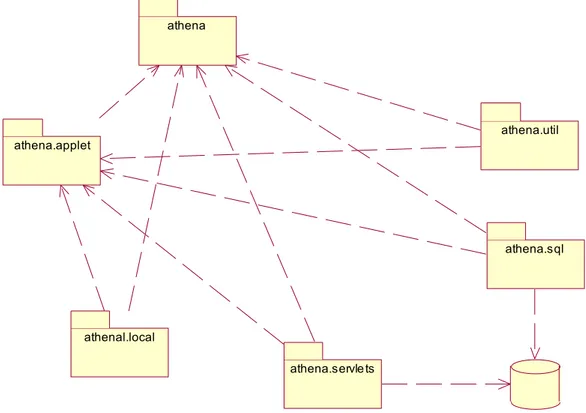
This view exists only in the software architecture instance and uses UML com-ponent diagrams to show the organization of executable code modules. Since Java has been decided to be the implementation platform, the component diagrams depict Java classes, interfaces and packages.
athena.applet
athenal.local
athena.sql athena.util
athena.servlets
Athena database athena
Figure 4 - The first-level components in the implementation view
Figure 4 shows that the system is decomposed on a first level in six packages:
• athena – it corresponds to the main component of the logical view that initializes and launches all the other components.
• athena.applet – it contains all the applets that are executed within the client’s browser.
• athena.local – it contains some command-line utilities that are executed locally on the server for maintenance purposes.
• athena.servlets – it contains all the servers and Java Server Pages
• athena.sql – it contains all the database access mechanisms, as well as the persistent objects management component.
• athena.util – it contains all the utility classes, e.g. for the construction of Graphical User Interface components.
3.3.3 The deployment view
The implementation decisions in the deployment view concern the identification of the various computational nodes and protocols specified in the reference architecture. Having in mind Figure 3, the application server is replaced by a J2EE Server, while the RDBMS node is replaced by a MySQL server. Furthermore the Remote Procedure Call (RPC) generic protocol that supports the realization of method calls to remote compo-nents, is now replaced by the Java Remote Method Invocation (RMI) API. Finally the Open Database Connectivity (ODBC) protocol for database connection is now replaced by JDBC, which is the corresponding ODBC protocol for Java.
3.4
The ‘Athena’ Architectural Prototype
A software architecture must be accompanied with an architectural prototype
that implements the most important design decisions sufficiently to validate them - that is to test and measure them [8, 10, 21]. In order to assess and validate the software ar-chitecture instance discussed above, a prototype was engineered that implements the main architectural elements. depicts some of the features of the ‘Athena’ LMS in action.
Search through metadata (conforming with LOM)
Calendar
Test authoring tool (conforming with QTI) Statistics for Student Tracking Figure 5. Screenshots of the architectural prototype
About 75% of the total number of components have been implemented or ac-quired and put into operation. In addition to the third-party components mentioned in a previous section, the layered architecture components that were implemented from scratch are: Main Subsystem, User Management, Courseware Authoring, Courseware Delivery, Course Management, Searching, Assessment, Help Desk, Data Base client, Raw Data Management, Business Objects Management, FTP client, Metadata
ment, Calendar, Communication Management (E-mail client, Chat server and client, Whiteboard server and client, Announcements tool), Data Store Access API.
Finally there was an attempt on implementing some of the international stan-dards within the various components, as dictated by the reference architecture. For that purpose the metadata management component has been developed to conform to the IEEE LTSC Learning Object Metadata working standard [14]; the assessment compo-nent has been implemented in order to adopt the IMS Question and Testing Interopera-bility Standard [16]; the Courseware Delivery component has adopted the IMS Learning Design [17]; the School Administration component has adopted both the IMS Learner Information and Package [18] and the IMS Competency Definition[19]. Although most of these standards are not yet in their final form, the aim of implementing them at such an early stage was to explore the feasibility of implementing them into our components.
4
Evaluation of the reference architecture
Software architectures can be evaluated according to specific criteria and are de-signed to fulfill certain quality attributes [8, 10, 6]. It is noted that no quality can be maximized in a system without sacrificing some other quality or qualities, instead there is always a trade-off between the different quality attributes [8, 10, 6]. Architectures can be evaluated through special evaluation techniques. These techniques do not assess the quality characteristics of end-products but measure the architecture’s ability to satisfy them and indicate where the architecture ‘is at’ in terms of quality.
The evaluation framework used for the assessment of the proposed reference ar-chitecture with respect to the quality attributes is comprised of a combination of two techniques adopted from [8]:
• Scenario-based evaluation, which is based on creating a set of scenar-ios, in order to evaluate a specific quality attribute. For example the in-teroperability quality can be evaluated by creating scenarios of exchang-ing data between the system under development and other systems, and evaluating the level of success in these interoperations.
• Architectural prototype evaluation, which is based on implementing only some of the parts of the architecture while the rest are ignored. The architectural prototype used is the ‘Athena’ LMS presented in the previ-ous section.
As far as the quality criteria that were evaluated, these were adopted from [6]: • Run-time qualities (performance, security, availability, functionality,
usability)
• Development qualities (modifiability, portability, integrability, interop-erability, reusability, testability).
most of the cases was qualitative and not quantitative as there are no metrics yet for these techniques [8]. It is rather obvious that this evaluation framework does not evalu-ate the reference architecture per se; instead it examines the architectural prototype which is an implementation of the software architecture instance, which in turn is an in-stantiation of the reference architecture. Therefore, the results from the evaluation can be attributed to the reference architecture, if and only if they do not rely on implementa-tion decisions. If they are directly based on implementaimplementa-tion decision they can only be ascribed to the software architecture instance.
As an example of an implementation-independent evaluation result it can be claimed that the layered nature of the system supports modifiability, since the function-ality is separated between layers and components can be modified without affecting components from other layers. This claim has also been proven right during the evalua-tion of the architectural prototype. On the other hand the layered nature of the system has a considerable cost on performance since there is a lot of communication overhead between independent components. Hence it can be claimed that the reference architec-ture supports modifiability but diminishes performance.
As a example of an evaluation result that relies on implementation decisions, we can consider the use of the Java programming language on the architectural prototype. Be-ing an interpreted language and relyBe-ing on a virtual machine, Java is platform-independent, thus allowing portability, at least to an extent and this has been also veri-fied in the architectural prototype. However this evaluation result can only be attributed to the ‘Athena’ architectural instance and not to the reference architecture, since it di-rectly involves an implementation decision.
The complete evaluation can be found in [2, 5]. It will suffice to say here that the architecture scored pretty high in the development qualities such as interoperability, modifiability, integrability, reusability and testability. On the other hand the architecture had a medium score in the run-time qualities such as performance, security, and avail-ability. This result is exactly what had been sought after in the desirable qualities of the reference architecture, as aforementioned in Section 2.6. The contradiction in the evaluation results between the run-time and the development qualities makes sense from an architectural point of view, since the development qualities are often in direct con-flict with the run-time qualities.
5
Conclusions and Future Work
This paper has proposed a description of a reference architecture, with the aid of the IEEE 1471 std., and the architecting practices of the Unified Software Development Process and the Unified Modeling Language. It has also demonstrated the differences between the description of a reference architecture and a software architecture that in-stantiates the former. Finally it has shown a plain evaluation framework that can be used for the assessment of the quality attributes, emphasizing on distinguishing the
tion results among those relied on implementation decisions and those that are inde-pendent.
Describing a reference architecture for a domain of systems and instantiating it into software architectures is not a straight forward process and there is no ‘silver bullet’ for accomplishing it. However the benefits gained from establishing a reference archi-tecture for a domain are highly rewarding [6, 8, 20, 7]:
• It is reusable in the sense that it can be adopted for the design of architectural instances and therefore the development of new systems, thus achieving a more
disciplined, systematic approach in this particular domain.
• It allows the ‘a priori’ analysis and evaluation of quality attributes, assuring the quality of the systems that will be designed according to the reference archi-tecture. The architectural instances that will be produced will be based on a ref-erence architecture that has already been evaluated and consequently satisfies some desirable quality attributes. This is of major importance as it eliminates the need to perform radical changes to the systems under development during the final development stages. Such changes are not just costly, they are often not feasible.
• It isn’t a blueprint for designing a single system, but a framework for design-ing a range of systems over time, thus achievdesign-ing adaptability to new trends and technologies.
• It grants a tangible product that represents a high-level abstraction of the sys-tem, assisting to the comprehension of the systems under development, their subsystems, and their interactions with related systems. In this sense it can help the training of apprentices to programming this particular domain of systems. • It allows for the analysis and comparison between different systems, with
re-spect to the reference architecture.
• Since the systems based on the reference architecture will contain implementa-tions of the components prescribed in it, a pool of such components can be es-tablished, so that these components can be reused in new systems being devel-oped.
• It can be used for the interoperation between the systems developed since they offer the same functionality through interfaces.
• It offers an effective basis for managing the development project, as it organ-izes the development process, offering the structure upon which the workload will be administered in each development iteration.
Currently we are working on designing and implementing more instances of the reference architecture, taking other implementation decisions in each case, e.g. other development platforms or different third-party components. This will further demon-strate the feasibility of the reference architecture, lead to useful conclusions, with re-spect to the range of possible implementations and provide valuable feedback to the ref-erence architecture per se. It will also reveal further more the relation between evaluation results and implementation decisions, providing a more extensive test-bed.
6
References
1. Avgeriou, P., Retalis, S. and Papaspyrou, N., “Modeling a Learning Technology System as a Business System”, (in press) Software and System Modelling Journal (SoSyM), Springer-Verlag, 2003.
2. Avgeriou, P., Retalis, S., Skordalakis, E., “Building Quality Into Learning Management Systems – An Architec-ture-Centric Approach”, (forthcoming volume of) Lecture Notes in Computer Science, Springer-Verlag. 3. Avgeriou, P., Papasalouros, A., Retalis, S., “Towards a Pattern Language for Learning Management Systems”,
ΙΕΕΕ Educational Technology & Society (accepted for publication).
4. Avgeriou, P., Architectural Description of the “Athena” Learning Management System that conforms to the IEEE 1471-2000 standard, National Technical University of Athens, Software Engineering Laboratory Technical Re-port CSD-SW-TR-1-02, 2002.
5. Avgeriou, P., A Reference Architecture For Open Learning Management Systems, PhD thesis, January 2003, Na-tional Technical University of Athens.
6. Bass, L., Clements, P., Kazman, R.: Software Architecture in Practice. Addison-Wesley, 1998. 7. Booch, G., Rumbaugh, J., Jacobson, I.: The UML User Guide. Addison-Wesley, 1999. 8. Bosch, J.: Design and Use of Software Architectures. Addison-Wesley, 2000.
9. Buschmann, F., Meunier, R., Rohnert, H., Sommertland, P. and Stal, M., 1996. Pattern-Oriented Software Archi-tecture, Volume 1: A System of Patterns, John Wiley & Sons.
10.Clements, P., Kazman, R., Clein, M., Evaluating Software Architecture, Addison-Wesley, 2002.
11.Collier, G., “Elearning application Infrastructure”, Sun Microsystems white paper, http://www.sun.com/products-n-solutions/edu/whitepapers/index.html, January 2002.
12.Hofmeister, C., Nord, R. and Soni, D., “Applied Software Architecture”, Addison-Wesley, 1999.
13.IEEE Learning Technology Standards Committee (LTSC), Draft Standard for Learning Technology Systems Ar-chitecture (LTSA), Draft 9, November 2001, http://ltsc.ieee.org/.
14.IEEE Learning Technology Standards Committee, (LTSC), Draft Standard for Learning Object Metadata (LOM), Draft 6.4, 2001, http://ltsc.ieee.org.
15.IEEE Recommended Practice for Architectural Description of Software-Intensive Systems (IEEE std. 1471-2000).
16.IMS Global Learning Consortium, 2001. IMS Question & Test Interoperability Specification- Best Practice and Implementation Guide, version 1.2.1, http://www.imsproject.org/.
17.IMS Global Learning Consortium, “IMS Learning Design”, 2001.
18.IMS Global Learning Consortium, “IMS Learner Information and Package (LIP)”, 2002. 19.IMS Global Learning Consortium, “IMS Competency Definition”, 2002.
20.Jacobson, I., Booch, G., Rumbaugh, J.: The Unified Software Development Process. Addison-Wesley, 1999. 21.Kruchten, P., 1999. The Rational Unified Process, An introduction, Addison-Wesley.
23.Putman, J., Architecting with RM-ODP, Prentice Hall, 2001.
24.The Rational Unified Process, 2000, v. 2001.03.00.23, Rational Software Corporation, part of the Rational Solu-tions for Windows suite.
25.Rumbaugh, J., Jacobson, I. and Booch, G., 1999. The UML Reference Manual, Addison-Wesley.
26.Shaw, M., Garlan, D.: Software Architecture - Perspectives on an emerging discipline. Prentice Hall, 1996. 27.Wilson,S., The next big thing? Three architectural frameworks for learning technologies, IMS Summit, August