625
Magnetic Induction
Conceptual Problems
*1 •
Determine the Concept We know that the magnetic flux (in this case the magnetic field because the area of the conducting loop is constant and its orientation is fixed) must be changing so the only issues are whether the field is increasing or decreasing and in which direction. Because the direction of the magnetic field associated with the clockwise current is into the page, the changing field that is responsible for it must be either increasing out of the page (not included in the list of possible answers) or a decreasing field directed into the page. (d )iscorrect.
2 •
Determine the Concept Note that when R is constant, B in the loop to the right points
out of the paper.
(a) If R increases, I decreases and so does B. By Lenz’s law, the induced current is counterclockwise.
(b) If R decreases, the induced current is clockwise. 3 ••
Determine the Concept If the counterclockwise current in loop A increases, so does the magnetic flux through B. To oppose this increase in flux, the induced current in loop B will by clockwise. If the counterclockwise current in loop A decreases, so does the magnetic flux through B. To oppose this decrease in flux, the induced current in loop B will be counterclockwise. We can use Fr =Irl×Brto determine the direction of the forces on each loop and, hence, whether they will attract or repel each other.
(a) If the current in B is clockwise the loops repel one another.
(b) If the current in B is counterclockwise the loops attract one another. 4 ••
Determine the Concept We know that, as the magnet moves to the right, the flux through the loop first increases until the magnet is half way through the loop and then decreases. Because the flux first increases and then decreases, the current will change directions, having its maximum values when the flux is changing most rapidly.
time as the bar magnet passes through the coil. When the center of the magnet passes through the plane of the coil dφm /dt = 0 and the current is zero.
-1.0 -0.8 -0.6 -0.4 -0.2 0.0 0.2 0.4 0.6 0.8 1.0
-3 -2 -1 0 1 2 3
time (arbitrary units)
Flux Current
5 ••
Determine the Concept Because the magnet moves with simple harmonic motion, the flux and the induced current will vary sinusoidally. The current will be a maximum wherever the flux is changing most rapidly and will be zero wherever the flux is momentarily constant.
(a), (b) The following graph shows the flux, φm , and the induced current (proportional to
−dφm/dt)in the loop as a function of time.
-1.0 -0.8 -0.6 -0.4 -0.2 0.0 0.2 0.4 0.6 0.8 1.0
-5 0 5 10 15
*6 •
Determine the Concept The magnetic energy stored in an inductor is given by
2 2 1
m
LI
U
=
. Doubling I quadruples Um. (c )iscorrect.7 •
Determine the Concept The protection is needed because if the current is suddenly interrupted, the resulting emf generated across the inductor due to the large flux change can blow out the inductor. The diode allows the current to flow (in a loop) even when the switch is opened.
8 •
Determine the Concept The inductance of a coil depends on the product n2
l, where n is the number of turns per unit length and l is the length of the coil. If n increases by a factor of 3, l will decrease by the same factor, because the inductors are made from the same length of wire. Hence, the inductance increases by a factor of
( ) ( )
32 13 = 3.
9 •
(a) False. The induced emf in a circuit is proportional to the rate of change of the magnetic flux through the circuit.
(b) True. (c) True.
(d) False. The inductance of a solenoid is determined by its length, cross-sectional area, number of turns per unit length, and the permeability of the matter in its core.
(e) True. *10 •
Determine the Concept In the configuration shown in (a), energy is dissipated by eddy currents from the emf induced by the pendulum movement. In the configuration shown in (b), the slits inhibit the eddy currents and the braking effect is greatly reduced. 11 •
Determine the Concept The time varying magnetic field of the magnet sets up eddy currents in the metal tube. The eddy currents establish a magnetic field with a magnetic moment opposite to that of the moving magnet; thus the magnet is slowed down. If the tube is made of a nonconducting material, there are no eddy currents.
12 ••
current resulting from this induced emf is in such a direction that its magnetic field opposes the changing flux in the coil, i.e., the current induced in the ring will be in such a direction that the magnetic field in the coil will repel it. The demonstration will not work if a slot is cut in the ring, because the emf will not be able to induce a current in the ring.
Estimation and Approximation
*13 ••
Picture the Problem We can use Faraday’s law to relate the induced emf to the angular velocity with which the students turn the jump rope.
(a) It seems unlikely that the students could turn the ″jump rope″
wire faster than 5 revolutions per second. This corresponds to a maximum angular velocity of:
rad/s.
31.4
rev
rad
2
s
rev
5
×
=
=
π
ω
(b) The magnetic flux φmthrough
the rotating circular loop of wire varies sinusoidally with time according to:
t BA
ω
φ
m = sinand
t
BA
dt
d
φ
ω
ω
cos
m
=
Because the average value of the cosine function, over one
revolution, is ½, the average rate at which the flux changes through the circular loop is:
ω
π
ω
φ
B r BA
dt
d 2
2 1 2
1 av
m = =
From Faraday’s law, the magnitude
of the induced emf in the loop is:
ε
=
d
dt
φ
m=
21π
r
2B
ω
Substitute numerical values and evaluate
ε
:(
31
.
4
rad/s
)
1
.
94
mV
G
10
T
1
G
7
.
0
2
m
5
.
1
4 2
2
1
=
⎟⎟
⎠
⎞
⎜⎜
⎝
⎛
×
⎟
⎠
⎞
⎜
⎝
⎛
=
π
ε
(c)
faster. times 500 about rope jump the
rotate to have would students the
V, 1 of emf an generate To
No.
(d)
emf.
induced
the
increase
would
around
times
several
looped
speed)
angular
same
at the
rotated
be
could
wire
composite
that the
(so
re
lighter wi
of
strands
multiple
of
use
The
14 •
The energy density in an electric field E is given by:
2 0 e
2
1
E
u
=
∈
The energy density in a magnetic
field B is given by: 0
2 m
2
µ
B
u
=
Express the ratio of um to ue to
obtain:
2 0 0
2 2
0 0 2
e m
2 1
2
E B E
B
u u
∈ = ∈ =
µ
µ
Substitute numerical values and evaluate um/ ue:
(
)
(
7 2)(
12 2 2)
(
)
2 42 5 e
m 2.25 10
V/m 100 m N / C 10 85 . 8 N/A 10 4
T 10
5 = ×
⋅ ×
×
×
== − −−
π
u u
or
(
)
e4 m 2.25 10 u
u = ×
15 ••
Picture the Problem We can apply Faraday’s law to estimate the maximum emf induced by the lightning strike in the antenna.
Use Faraday’s law to express the
magnitude of the induced emf in antenna:
ε
=
d
dt
φ
m=
dt
d
[ ]
BA
where A is the area of the antenna. Because the lightning strike has such
a short duration:
ε
≈
BA
∆
t
The magnetic field induced in theloop is given by:
B
=
4
µ
π
02
r
I
=
2
µ
π
0I
r
where r is the distance from the antenna to the lightning strike.
Substitute for B to obtain:
t
r
IA
∆
=
π
µ
ε
2
0
Substitute numerical values and
evaluate
ε
:(
)
(
)
(
)( )
kV
00
.
2
s
1
m
300
2
m
1
.
0
s
1
C
30
N/A
10
4
7 2 2=
⎟⎟
⎠
⎞
⎜⎜
⎝
⎛
×
=
−
µ
π
µ
π
Magnetic Flux
16 •
Picture the Problem Because the surface is a plane with area A and
B
r
is constant in magnitude and direction over the surface and makes an angle θwith the unit normal vector, we can useφ
m = BAcosθ
to find the magnetic flux through the coil. Substitute for B and A to obtain:(
)
(
)
θ
θ
φ
cos Wb 10 00 . 5 cos m 10 5 G 10 T 1 G 2000 4 2 2 4 m − − × = × ⎟⎟ ⎠ ⎞ ⎜⎜ ⎝ ⎛ ⋅ =(a) For θ = 0°:
(
)
mWb 500 . 0 Wb 10 00 . 5 0 cos Wb 10 00 . 5 4 4 m = × = ° × = − −
φ
(b) For θ = 30°:
(
)
mWb 433 . 0 Wb 10 33 . 4 cos30 Wb 10 00 . 5 4 4 m = × = ° × = − −
φ
(c) For θ = 60°:
(
)
mWb 250 . 0 Wb 10 50 . 2 cos60 Wb 10 00 . 5 4 4 m = × = ° × = − −
φ
(d) For θ = 90°:
(
)
0
cos90
Wb
10
00
.
5
4 m=
°
×
=
−φ
*17 •
Picture the Problem Because the coil defines a plane with area A and
B
r
is constant in magnitude and direction over the surface and makes an angle θwith the unit normal vector, we can useφ
m = NBAcosθ
to find the magnetic flux through the coil. Substitute for N, B, and A to obtain:(
)
(
)
θ
θ
π
θ
π
φ
cos Wb 10 37 . 1 cos m 10 5 G 10 T 1 G 7 . 0 25 cos 5 2 2 4 2 m − − × = × ⎟⎟ ⎠ ⎞ ⎜⎜ ⎝ ⎛ ⋅ =(a) When the plane of the coil is horizontal, θ = 90°:
(
)
0
90
cos
Wb
10
37
.
1
5m
=
°
×
=
−φ
(b) When the plane of the coil is vertical with its axis pointing north,
θ = 0°:
(
)
Wb 10 37 . 1
0 cos Wb 10 37 . 1
5 5 m
− −
× =
° ×
=
φ
(c) When the plane of the coil is vertical with its axis pointing east,
θ = 90°:
(
)
0
90
cos
Wb
10
37
.
1
5m
=
°
×
=
−φ
(d) When the plane of the coil is vertical with its axis making an angle of 30° with north, θ = 30°:
(
)
Wb 10 19 . 1
30 cos Wb 10 37 . 1
5 5 m
− −
× =
° ×
=
φ
18 •
Picture the Problem Because the square coil defines a plane with area A and
B
r
is constant in magnitude and direction over the surface and makes an angle θwith the unit normal vector, we can useφ
m = NBAcosθ
to find the magnetic flux through the coil. Substitute for N, B, and A to obtain:(
)
(
)
(
)
θ
θ
θ
φ
cos
mWb
0
.
42
cos
m
10
5
T
2
.
1
14
cos
2 2 m
=
×
=
=
−
NBA
(a) For θ = 0°:
(
)
mWb
0
.
42
0
cos
mWb
0
.
42
m
=
°
=
φ
(b) For θ = 60°:
(
)
mWb
0
.
21
60
cos
mWb
0
.
42
m
=
°
=
φ
19 •
Picture the Problem Noting that the flux through the base must also penetrate the spherical surface, we can apply its definition to express φm.
Apply the definition of magnetic flux to obtain:
B R
AB 2
m
π
20 ••
Picture the Problem We can use
φ
m =NBAcosθ
to express the magnetic flux through the solenoid andB
=
µ
0nI
to relate the magnetic field in the solenoid to the current in its coils.Express the magnetic flux through a coil with N turns:
θ
φ
m = NBAcosExpress the magnetic field inside a long solenoid:
nI
B
=
µ
0where n is the number of turns per unit length.
Substitute to obtain:
φ
m=
N
µ
0nIA
cos
θ
or, because n = N/L and θ = 0°,
L
r
I
N
L
IA
N
20 2 0
2 m
π
µ
µ
φ
=
=
Substitute numerical values and evaluate φm:
( )
(
)
( ) (
)
7
.
58
10
Wb
m
25
.
0
m
0.01
π
A
3
N/A
10
4
400
2 7 2 2 4m
− −
×
=
×
=
π
φ
21 ••
Picture the Problem We can use
φ
m = NBAcosθ
to express the magnetic flux through the solenoid andB
=
µ
0nI
to relate the magnetic field in the solenoid to the current in its coils.Express the magnetic flux through a coil with N turns:
θ
φ
m = NBAcosExpress the magnetic field inside a long solenoid:
nI
B
=
µ
0where n is the number of turns per unit length.
Substitute to obtain:
φ
m=
N
µ
0nIA
cos
θ
or, because n = N/L and θ = 0°,
L
r
I
N
L
IA
N
20 2 0
2 m
π
µ
µ
Substitute numerical values and evaluate φm:
( )
(
)
( ) (
)
6
.
74
10
Wb
m
3
.
0
m
0.02
A
2
N/A
10
4
800
3 2 2 7 2 m − −×
=
×
=
π
π
φ
22 ••
Picture the Problem We can apply the definitions of magnet flux and of the dot product to find the flux for the given unit vectors.
Apply the definition of magnetic
flux to the coil to obtain:
∫
⋅
=
S
dA
N
B
n
ˆ
m
r
φ
Because
B
r
is constant:( )
( )
2m ˆ ˆ ˆ r N A N dA N S
π
φ
n B n B n B ⋅ = ⋅ = ⋅ =∫
r r rEvaluate
B
r
:B
r
=
(
0
.
4
T
)
i
ˆ
Substitute numerical values andsimplify to obtain:
( )(
[
)
]
(
)
(
0
.
0302
T
m
)
i
ˆ
n
ˆ
m
04
.
0
T
4
.
0
15
2 2 m⋅
⋅
=
=
π
φ
(a) Evaluate φm for nˆ=iˆ:
φ
m =(
0.0302T⋅m2)
iˆ⋅iˆ= 0.0302Wb(b) Evaluate φm for
n
ˆ
=
ˆ
j
:φ
m =(
0.0302T⋅m2)
iˆ⋅ jˆ= 0(c) Evaluate φm for
n
ˆ
=
( )
i
ˆ
+
ˆ
j
2
:(
)
( )
Wb
0213
.
0
2
m
T
0302
.
0
2
ˆ
ˆ
ˆ
m
T
0302
.
0
2 2 m=
⋅
=
+
⋅
⋅
=
i
i
j
φ
(d) Evaluate φm for nˆ =kˆ:
φ
m =(
0.0302T⋅m2)
iˆ⋅kˆ= 0(e) Evaluate φm for
n
ˆ
=
0
.
6
i
ˆ
+
0
.
8
ˆ
j
:(
)
(
)
(
)
(
)
(
0
.
0302
T
m
)
0
.
0181
Wb
23 ••
Picture the Problem The magnetic field outside the solenoid is, to a good approximation, zero. Hence, the flux through the loop is the flux in the core of the solenoid. The magnetic field inside the solenoid is uniform. Hence, the flux through this small loop is given by the same expression with R3 replacing R1:
(a) Express the flux through the large circular loop outside the solenoid:
2 1 0
m NBA
µ
nINπ
Rφ
= =(b) Express the flux through the small loop inside the solenoid:
2 3 0
m NBA
µ
nINπ
Rφ
= =*24 ••
Picture the Problem We can use the hint to set up the element of area dA and express the flux dφm through it and then carry out the details of the integration to express φm.
(a) Express the flux through the strip of area dA:
BdA d
φ
m =where dA = bdx. Express B at a distance x from a
long, straight wire:
x
I
x
I
B
π
µ
π
µ
2
2
4
0
0
=
=
Substitute to obtain:
x
dx
Ib
bdx
x
I
d
π
µ
π
µ
φ
2
2
0 0
m
=
=
Integrate from x = d to x = d + a:
d a d Ib x
dx Ibd a
d
+ =
=
∫
+ ln2 2
0 0
m
π
µ
π
µ
φ
(b) Substitute numerical values and evaluate φm:
(
)
(
)(
)
Wb 10 5.01 cm
2 cm 7 ln 2
m 0.1 A 20 N/A 10
4 7 2 7
m
− −
× =
⎟⎟ ⎠ ⎞ ⎜⎜ ⎝ ⎛ ×
=
π
π
φ
25 •••
Picture the Problem Consider an element of area dA = Ldr where r≤R. We can use its definition to express dφm through this area in terms of B and Ampere’s law to express B
as a function of I. The fact that the current is uniformly distributed over the
Express the flux dφm through an area
Ldr:
BLdr BdA
d
φ
m = = (1)Apply Ampere’s law to the current contained inside a cylindrical region of radius r < R:
C C ⋅d =2
π
rB=µ
0I∫
Br rland
r
I
B
Cπ
µ
2
0
=
Using the fact that the current I is uniformly distributed over the cross-sectional area of the conductor, express its variation with distance r from the center of the conductor:
2 2
)
(
R
r
I
r
I
π
π
=
or
( )
22R
r
I
I
r
I
=
C=
Substitute and simplify to obtain:
r
R
I
R
r
r
I
B
0 22 2 0
2
2
π
µ
π
µ
=
=
Substitute in equation (1):
rdr R LI
d 0 2
m 2π
µ
φ
=Integrate dφm from r = 0 to r = R to
obtain:
π
µ
π
µ
φ
4 2
0 0
2 0 m
LI rdr
R LI R
=
=
∫
Divide both sides of this equation by L to express the magnetic flux per unit length:
π
µ
φ
4
0
m I
L =
26 •••
Picture the Problem We can use its definition to express the flux through the rectangular region and Ampere’s law to relate the magnetic field to the current in the wire and the position of the long straight wire.
(a) Note that for 0 ≤x≤b, B is symmetric about the wire, into the paper for the region below the wire and out of the paper for the region above the wire. Thus, for the area 2(b−x)a:
0
net m,
=
φ
remaining area of the rectangle, express the flux through a strip of area dA:
where dA = adx.
Using Ampere’s law, express B at a distance x from a long, straight wire:
x
I
x
I
B
π
µ
π
µ
2
2
4
0
0
=
=
Substitute to obtain:
x
dx
Ia
adx
x
I
d
π
µ
π
µ
φ
2
2
0 0
m
=
=
For 0 ≤x≤b, integrate from
x′ = b − x to x′ = x :
(
)
⎟
⎠
⎞
⎜
⎝
⎛
−
=
=
≤
≤
∫
−
x
b
x
Ia
x'
dx'
Ia
b
x
x
x b
ln
2
2
0
0 0 m
π
µ
π
µ
φ
For x≥ b, integrate from
x′ = x to x′ = x + b:
(
)
⎟
⎠
⎞
⎜
⎝
⎛ +
=
=
≥
∫
+x
b
x
Ia
x'
dx'
Ia
b
x
b x
x
ln
2
2
0 0 m
π
µ
π
µ
φ
(b) From the expressions derived in (a) we see that
φ
m →∞as:0
→
x
The flux is a minimum (φm = 0) for: x= 21b as expected from symmetry.
Induced EMF and Faraday’s Law
*27 •
Picture the Problem We can find the induced emf by applying Faraday’s law to the loop. The application of Ohm’s law will yield the induced current in the loop and we can find the rate of joule heating using
P
=
I
2R
.(a) Apply Faraday’s law to express the induced emf in the loop in terms of the rate of change of the
magnetic field:
( )
dt
dB
R
dt
dB
A
AB
dt
d
dt
d
φ
mπ
2ε
=
=
=
=
evaluate
ε
:(b) Using Ohm’s law, relate the induced current to the induced voltage and the resistance of the loop and evaluate I:
mA
0.785
Ω
0.4
mV
0.314
=
=
=
R
I
ε
(c) Express the rate at which power is dissipated in a conductor in terms of the induced current and the resistance of the loop and evaluate P:
(
) (
)
W 0.247
Ω 0.4 mA
0.785 2
2
µ R I P
= = =
28 •
Picture the Problem Given φm as a function of time, we can use Faraday’s law to
express
ε
as a function of time.(a) Apply Faraday’s law to express the induced emf in the loop in terms of the rate of change of the
magnetic field:
(
)
[
]
(
)
(
0
.
2
0
.
4
)
V
Wb/s
10
4
2
Wb
10
4
1
1 2
m
−
−
=
×
−
−
=
×
−
−
=
−
=
−
−
t
t
t
t
dt
d
dt
d
φ
ε
(b) Evaluate φm at t = 0:
φ
m( ) ( )
0s =[
0 2−4( )
0]
×10−1Wb= 0Evaluate
ε
at t = 0:( )
[
( )
]
V
400
.
0
V
4
.
0
0
2
.
0
s
0
=
−
−
=
ε
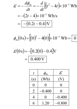
Proceed as above to complete the table to the right:
t φm
ε
(s) (Wb) (V) 0 0 0 2 −0.400 0 4 0 −0.400 6 1.20 −0.800
29 •
(a) The flux,φm, and the induced emf,
ε
, are shown as functions of t in the followinggraph. The solid curve represents φm, the dashed curve represents
ε
.
-1.0 -0.5 0.0 0.5 1.0 1.5
0 1 2 3 4 5 6
t (s)
flux emf
(b)
instant. at this
0 that
and s 2 at minimum a
is flux that the see
we graph, the to Referring
=
=
V
t
(c)
ly. respective
V, 0.4 and V 0.4 times,
At these s.
4 and 0 at zero is flux
The t= t=
ε
= −30 •
Picture the Problem We can use its definition to find the magnetic flux through the solenoid and Faraday’s law to find the emf induced in the solenoid when the external field is reduced to zero in 1.4 s.
(a) Express the magnetic flux through the solenoid in terms of N, B, A,and θ:
θ
π
θ
φ
cos
cos
2 m
R
NB
NBA
=
=
Substitute numerical values and evaluate φm:
( )(
) (
)
mWb 10 . 3
50 cos m 008 . 0 T 06 . 0
400 2
m
=
°
=
π
(b) Apply Faraday’s law to obtain:
mV
22
.
2
s
1.4
mWb
3.10
0
m
=
−
−
=
−
=
dt
d
φ
ε
*31 ••
Picture the Problem We can use the definition of average current to express the total charge passing through the coil as a function of Iav. Because the induced current is
proportional to the induced emf and the induced emf, in turn, is given by Faraday’s law, we can express ∆Q as a function of the number of turns of the coil, the magnetic field, the resistance of the coil, and the area of the coil. Knowing the reversal time, we can find the average current from its definition and the average emf in the coil from Ohm’s law.
(a) Express the total charge that passes through the coil in terms of the induced current:
t
I
Q
=
∆
∆
avRelate the induced current to the
induced emf:
I
I
R
ε
=
=
avUsing Faraday’s law, express the
induced emf in terms of φm:
∆
t
∆
−
=
φ
mε
Substitute and simplify to obtain:
R
d
NB
R
d
NB
R
NBA
R
t
R
t
t
R
Q
2
4
2
2
2
2
2 m m
π
π
φ
φ
ε
−
=
⎟
⎠
⎞
⎜
⎝
⎛
−
=
−
=
−
=
∆
∆
∆
−
=
∆
=
∆
where d is the diameter of the coil. Substitute numerical values and
evaluate ∆Q:
( )( ) (
)
(
)
mC
26
.
1
50
2
m
02
.
0
T
1
100
2−
=
Ω
−
=
∆
Q
π
(b) Apply the definition of average
current to obtain:
0.1
s
12.6
mA
mC
1.26
av
∆
=
=
∆
=
(c) Using Ohm’s law, relate the average emf in the coil to the average current:
(
)(
)
mV
630
Ω
50
mA
12.6
av av
=
=
=
I
R
ε
32 ••
Picture the Problem We can use the definition of average current to express the total charge passing through the coil as a function of Iav. Because the induced current is
proportional to the induced emf and the induced emf, in turn, is given by Faraday’s law, we can express ∆Q as a function of the number of turns of the coil, the magnetic field, the resistance of the coil, and the area of the coil.
Express the total charge that passes through the coil in terms of the induced current:
t
I
Q
=
∆
∆
avRelate the induced current to the
induced emf:
I
I
R
ε
=
=
avUsing Faraday’s law, express the
induced emf in terms of φm:
∆
t
∆
−
=
φ
mε
Substitute to obtain:
R
NBA
R
t
R
t
t
R
Q
2
2
mm
−
=
−
=
∆
∆
∆
−
=
∆
=
∆
φ
φ
ε
Substitute numerical values and evaluate ∆Q:
(
)
(
)(
)
mC 280 . 0 15
m 10 300 T 10 7 . 0 1000
2 4 4 2
= Ω
× ×
− =
∆Q − −
33 ••
Picture the Problem We can use Faraday’s law to express the earth’s magnetic field at this location in terms of the induced emf and Ohm’s law to relate the induced emf to the charge that passes through the current integrator.
Using Faraday’s law, express the induced emf in terms of the change in the magnetic flux as the coil is rotated through 90°:
t r NB t
NBA
t = ∆ = ∆
∆ ∆ −
=
φ
mπ
2Solve for B:
2
r
N
t
B
π
ε∆
=
Using Ohm’s law, relate the induced
emf to the induced current:
t
R
Q
IR
∆
∆
=
=
ε
where ∆Q is the charge that passes through the current integrator.
Substitute to obtain:
2
2
N
r
QR
r
N
t
R
t
Q
B
π
π
∆
=
∆
∆
∆
=
Substitute numerical values and evaluate B:
(
)(
)
( ) (
300
0
.
05
m
)
79
.
8
T
Ω
20
µC
4
.
9
2
µ
π
=
=
B
34 ••
Picture the Problem We can use Faraday’s law to express the induced emf in the coil in terms of the rate of change of the magnetic flux. We can use its definition to express the magnetic flux through the rectangular region and Ampere’s law to relate the magnetic field to the current in the wire and the position of the long straight wire.
(a) Apply Faraday’s law to relate the induced emf to the changing magnetic flux:
dt
d
φ
mε
=
−
(1)Note that for 0 ≤x≤b, B is symmetric about the wire, into the paper for the region below the wire and out of the paper for the region above the wire. Thus, for the area 2(b−x)a:
0
net m,
=
φ
To find the flux through the remaining area of the rectangle, express the flux through a strip of area dA:
BdA d
φ
m =where dA = adx.
Using Ampere’s law, express B at a
distance x from a long, straight wire:
x
t
x
I
B
π
µ
π
µ
02
04
=
Substitute to obtain:
x
dx
ta
adx
x
t
d
π
µ
π
µ
φ
0 0m
=
=
For 0 ≤x≤b, integrate from
x′ = b − x to x′ = x :
(
)
⎟
⎠
⎞
⎜
⎝
⎛
−
=
=
≤
≤
∫
−x
b
x
ta
x'
dx'
ta
b
x
x x bln
0
0 0 mπ
µ
π
µ
φ
Differentiate this expression with respect to time to obtain:
⎟
⎠
⎞
⎜
⎝
⎛
−
=
⎥
⎦
⎤
⎢
⎣
⎡
⎟
⎠
⎞
⎜
⎝
⎛
−
=
x
b
x
a
x
b
x
ta
dt
d
dt
d
ln
ln
0 0 mπ
µ
π
µ
φ
Substitute in equation (1) and evaluate
ε
for x = b/4:π
µ
π
µ
π
µ
ε
a a b b b a 0 0 0 10 . 1 3 1 ln 4 4 ln = ⎟ ⎠ ⎞ ⎜ ⎝ ⎛ − = ⎟⎟ ⎠ ⎞ ⎜⎜ ⎝ ⎛ − − =(b) Using Ohm’s law, express and evaluate R:
(
)
(
)
(
)
Ω = × = = = −µ
π
π
π
µ
ε
60 . 6 A 1 . 0 m 5 . 1 N/A 10 4 10 . 1 10 . 1 2 7 0 I a I R ckwise. counterclo is current induced the Thus page. the of out be it will i.e, increase; this oppose will field magnetic its that direction a such in be ll current wi induced the page, the into increasing is to due flux magnetic the Because I35 ••
Picture the Problem We can use Faraday’s law to express the induced emf in the coil in terms of the rate of change of the magnetic flux. We can use its definition to express the magnetic flux through the rectangular region and Ampere’s law to relate the magnetic field to the current in the wire and the position of the long straight wire.
(a) Apply Faraday’s law to relate the induced emf to the changing magnetic flux:
dt
d
φ
mNote that for 0 ≤x≤b, B is symmetric about the wire, into the paper for the region below the wire and out of the paper for the region above the wire. Thus, for the area 2(b−x)a:
0
net m,
=
φ
To find the flux through the remaining area of the rectangle, express the flux through a strip of area dA:
BdA d
φ
m =where dA = adx.
Using Ampere’s law, express B at a distance x from a long, straight wire:
x
t
x
I
B
π
µ
π
µ
02
04
=
=
Substitute to obtain:
x
dx
ta
adx
x
t
d
π
µ
π
µ
φ
0 0m
=
=
For 0 ≤x≤b, integrate from
x′ = b − x to x′ = x :
(
)
⎟
⎠
⎞
⎜
⎝
⎛
−
=
=
≤
≤
∫
−x
b
x
ta
x'
dx'
ta
b
x
x x bln
0
0 0 mπ
µ
π
µ
φ
Differentiate this expression with respect to time to obtain:
⎟
⎠
⎞
⎜
⎝
⎛
−
=
⎥
⎦
⎤
⎢
⎣
⎡
⎟
⎠
⎞
⎜
⎝
⎛
−
=
x
b
x
a
x
b
x
ta
dt
d
dt
d
ln
ln
0 0 mπ
µ
π
µ
φ
Substitute in equation (1) and evaluate
ε
for x = b/3:π
µ
π
µ
π
µ
ε
a a b b b a 0 0 0 693 . 0 2 1 ln 3 3 ln = ⎟ ⎠ ⎞ ⎜ ⎝ ⎛ − = ⎟⎟ ⎠ ⎞ ⎜⎜ ⎝ ⎛ − − =(b) Using Ohm’s law, express and evaluate R:
ckwise. counterclo
is current induced
the Thus, page. the of out be it will i.e, increase, this
oppose will
field magnetic its
that direction a
such in be ll current wi induced
the page, the into increasing is
to due flux magnetic the
Because I
Motional EMF
*36 •
Picture the Problem We can apply the equation for the force on a charged particle moving in a magnetic field to find the magnetic force acting on an electron in the rod. We can use Er =vr×Br to find E and V =El, where l is the length of the rod, to find the potential difference between its ends.
(a) Relate the magnetic force on an electron in the rod to the speed of the rod, the electronic charge, and the magnetic field in which the rod is moving:
B
v
F
r
=
q
r
×
r
andθ
sin
qvB
F
=
Substitute numerical values and evaluate F:
(
)
(
)(
)
N
10
6.40
sin90
T
0.05
m/s
8
C
10
1.6
20 19
− −
×
=
°
×
=
F
(b) Express the electrostatic field
E
r
in the rod in terms of the magnetic fieldB
r
:B v Er = r× r and
θ
sin vB E=
Substitute numerical values and evaluate B:
(
)(
)
V/m
0.400
sin90
T
0.05
m/s
8
=
°
=
E
(c) Relate the potential difference between the ends of the rod to its lengthland the electric field E:
l
E V =
Substitute numerical values and evaluate V:
(
0.4V/m)(
0.3m)
= 0.120V=
V
37 •
Express the electrostatic field
E
r
in the rod in terms of the magnetic fieldB
r
and solve for v:B v Er = r× r and
θ
sin
B
E
v
=
Relate the potential difference between the ends of the rod to its length land the electric field E and solve for E:
l
E
V = ⇒
l
V
E
=
Substitute for E to obtain:
θ
sin
l
B
V
v
=
Substitute numerical values and
evaluate v:
(
0.05
T
)(
0.3
m
)
400
m/s
V
6
=
=
v
38 •
Picture the Problem Because the speed of the rod is constant, an external force must act on the rod to counter the magnetic force acting on the induced current. We can use the motional-emf equation
ε
=vBlto evaluate the induced emf, Ohm’s law to find the current in the circuit, Newton’s 2nd law to find the force needed to move the rod withconstant velocity, and P = Fv to find the power input by the force. (a) Relate the induced emf in the
circuit to the speed of the rod, the magnetic field, and the length of the rod:
(
)(
)(
)
V
1.60
m
0.2
T
0.8
m/s
10
=
=
=
vB
l
ε
(b) Using Ohm’s law, relate the current in the circuit to the induced emf and the resistance of the circuit:
A
0.800
Ω
2
V
1.6
=
=
=
R
I
ε
Note that, because the rod is moving to the right, the flux in the region defined by the rod, the rails, and the resistor is increasing. Hence, in accord with Lenz’s law, the current must be counterclockwise if its magnetic field is to counter this increase in flux.
(c) Because the rod is moving with constant velocity, the net force acting on it must be zero. Apply
Newton’s 2nd law to relate F to the
magnetic force Fm:
(
0.8
T
)(
0.8
A
)(
0.2
m
)
0.128
N
m=
=
=
=
F
BI
l
F
(d) Express the power input by the force in terms of the force and the velocity of the rod:
(
0.128N)(
10m/s)
= 1.28W= =Fv P
(e) The rate of Joule heat production is given by:
(
0.8A) ( )
2 2Ω 1.28W2 = =
=I R P
39 ••
Picture the Problem We’ll need to determine how long it takes for the loop to
completely enter the region in which there is a magnetic field, how long it is in the region, and how long it takes to leave the region. Once we know these times, we can use its definition to express the magnetic flux as a function of time. We can use Faraday’s law to find the induced emf as a function of time.
(a) Find the time required for the loop to enter the region where there is a uniform magnetic field:
s
4.17
cm/s
2.4
cm
10
loop of
side
=
=
=
v
t
l
Letting w represent the width of the loop, express and evaluate φmfor
s
17
.
4
0
<
t
<
:(
(
)(
)
t)(
)
tNBwvt NBA
mWb/s 04
. 2
m/s 0.024 m
0.05 T 1.7
m
= =
= =
φ
Find the time during which the loop is fully in the region where there is a uniform magnetic field:
s
4.17
cm/s
2.4
cm
10
loop of
side
=
=
=
v
t
l
i.e., the loop will begin to exit the region when t = 8.33 s.
Express φmfor
4
.
17
s
<
t
<
8
.
33
s
:(
)(
)(
)
mWb 50 . 8
m 0.05 m 1 . 0 T 1.7
m
= =
= =NBA NBlw
φ
The left-end of the loop will exit the field when t = 12.5 s. Express φmfor
s
5
.
12
s
33
.
8
<
t
<
:b mt+ =
m
φ
where m is the slope of the line and b is the
φm-intercept.
For t = 8.33 s and
φm = 8.50 mWb:
(
)
bm +
= 8.33s mWb
50 .
For t = 12.5 s and φm = 0: 0=m
(
12.5s)
+b (2)Solve equations (1) and (2) simultaneously to obtain:
(
2.04mWb/s)
25.5mWbm =− t+
φ
The loop will be completely out of the magnetic field when t > 12.5 s and:
0
m =
φ
The following graph of
φ
m( )
t was plotted using a spreadsheet program.-1 0 1 2 3 4 5 6 7 8 9
0 2 4 6 8 10 12 14
t (s)
Mag
netic
flux
(mWb
)
(b) Using Faraday’s law, relate the
induced emf to the magnetic flux:
dt
d
φ
mε
=
−
During the interval
0
<
t
<
4
.
17
s
:[
(
)
]
mV
04
.
2
mWb/s
04
.
2
=
−
−
=
t
dt
d
ε
During the interval
s
33
.
8
s
17
.
4
<
t
<
:=
−
dt
[
8
.
50
mWb
]
=
0
d
ε
During the interval
s
5
.
12
s
33
.
8
<
t
<
:[
(
)
]
mV 04 . 2
mWb 5 . 25 mWb/s 2.04
-=
+ −
= t
dt d
ε
The following graph of ε(t) was plotted using a spreadsheet program.
-2.5 -2.0 -1.5 -1.0 -0.5 0.0 0.5 1.0 1.5 2.0 2.5
0 2 4 6 8 10 12 14
t (s)
em
f (V
)
40 ••
Picture the Problem The rod is executing simple harmonic motion in the xy plane, i.e., in a plane perpendicular to the magnetic field. The emf induced in the rod is a
consequence of its motion in this magnetic field and is given by
ε
=vBl. Because we’re given the position of the oscillator as a function of time, we can differentiate this expression to obtain v.Express the motional emf in terms
of v, B, and l:
dt
dx
B
vB
l
=
l
=
ε
Evaluate dx/dt:
[
(
)
]
(
)
(
)
(
)
t
t
t
dt
d
dt
dx
π
π
π
π
120
sin
m/s
54
.
7
120
sin
s
120
cm
2
120
cos
cm
2
1
−
=
−
=
=
−
Substitute numerical values and evaluate
ε
:(
)(
)(
)
π
t(
)
π
tε
=−1.2T 0.15m 7.54m/s sin120 = − 1.36V sin12041 ••
Newton’s 2nd law to relate its acceleration to B, I, andl. The net emf that drives I in this circuit is the emf of the battery minus the emf induced in the rod as a result of its motion.
(a) Letting the direction of motion of the rod be the positive x
direction, apply
x x
ma
F
∑
=
tothe rod:
dt
dv
m
BI
l
=
(1) whereR
v
B
I
=
ε
−
l
(2)Substitute to obtain:
(
)
v B mR
B dt dv
l
l −
=
ε
(b) Express the condition on dv/dt when the rod has achieved its terminal speed:
(
−
B
v
t)
=
0
mR
B
l
l
ε
Solve for vt to obtain:
l
B
v
t=
ε
(c) Substitute vtfor v in equation
(2) to obtain:
=
−
=
0
R
B
B
I
l
l
ε
ε
*42 ••
Picture the Problem In Example 28-9 it is shown that the speed of the rod is given by
v
v
e
(
B22mR)
t0 l
−
=
. We can use the definition of power and the expression for a motional emf to express the power dissipated in the resistance in terms of B,l, v, and R. We can then separate the variables and integrate over all time to show that the total energy dissipated is equal to the initial kinetic energy of the rod.Express the power dissipated in
terms of εand R:
P
R
2
ε
=
Express ε as a function of B, l, and v:
v Bl
=
ε
where(
B mR)
te
v
v
=
0 − 2l2Substitute to obtain:
( )
R
v
B
P
2
l
The total energy dissipated as the rod comes to rest is obtained by integrating dE = P dt:
( )
(
)
(
)
(
)
dt
e
R
v
B
dt
R
e
v
B
dt
R
v
B
E
t mR B
t mR B
∫
∫
∫
∞ −
∞ −
∞
=
=
=
0 2 2 0 2 2 0
2 0
0 2
2 2 2 2
l l
l
l
l
Evaluate the integral (by changing variables to
mR
B
u
2 2
2
l
−
=
) toobtain:
2 0 2 1 2 2 2 0 2 2
2B mv
mR R
v B
E ⎟=
⎠ ⎞ ⎜
⎝ ⎛ =
l l
43 ••
Picture the Problem In Example 28-9 it is shown that the speed of the rod is given by
v
=
v
0e
−(
B2l2mR)
t. We can write v as dx/dt, separate the variables and integrate to findthe total distance traveled by the rod.
Apply the result from Example 28-9 to obtain:
t
e
v
dt
dx
C0 −
=
where
mR
B
2 2C
=
l
Separate variables and integrate x′
from 0 to x and t′ from 0 to ∞:
∫
∫
∞ −
=
0 C 0 0
dt e v
dx' t
x
Evaluate the integrals to obtain:
C
0
v
x
=
Substitute for C and simplify:
2 20
l
44 ••
Picture the Problem Let m be the mass of the rod. The net force acting on the rod is due to the current in it. We can obtain the equation of motion for the rod by applying
Newton’s 2nd law to relate its acceleration to B, I, and
l. The net emf that drives I in this circuit is the emf of the capacitor minus the emf induced in the rod as a result of its motion.
(a) Letting the direction of motion of the rod be the positive x
direction, apply
x x
ma
F
∑
=
to the rod:dt
dv
m
BI
l
=
(1) whereR
v
B
C
Q
I
l
−
=
(2)Solve equation (1) for I:
dt
dv
B
m
I
l
=
or, because the capacitor is discharging,
dt
dv
B
m
dt
dQ
l
=
−
Simplify to obtain:
dv
B
m
dQ
l
−
=
Integrate Q′ from Q0 to Q and v′
from 0 to v:
∫
=
−
∫
v Q
Q
dv'
B
m
dQ
0
0
'
l
and
v
B
m
Q
Q
l
−
=
0Substitute in equation (2) to obtain:
R
v
B
CR
v
B
m
Q
R
v
B
C
v
B
m
Q
I
l
l
l
l
−
−
=
−
−
=
Substitute in equation (1) to obtain the equation of motion of the rod:
v mR B RC mRC
Q B
v B C
v B
m Q mR
B dt dv
⎟⎟ ⎠ ⎞ ⎜⎜
⎝ ⎛
+ −
=
⎟⎟ ⎟ ⎟
⎠ ⎞
⎜⎜ ⎜ ⎜
⎝ ⎛
− − =
2 2 0
0
1 l
l
l l l
(b) When the rod has achieved its
terminal speed:
=
dt
=
0
dv
m
BI
l
and
0
t f
=
−
=
R
v
B
C
Q
I
l
Solve for vt to obtain:
l
CB Q
v f
t =
*45 ••
Picture the Problem The free-body diagram shows the forces acting on the rod as it slides down the inclined plane. The retarding force is the component of Fm
acting up the incline, i.e., in the −x direction. We can express Fmusing the
expressionfor the force acting on a conductor moving in a magnetic field. Recognizing that only the horizontal component of the rod’s velocity vrproduces an induced emf, we can apply the
expression for a motional emf in conjunction with Ohm’s law to find the induced current in the rod. In part (b) we can apply Newton’s 2nd law to obtain an
expression for dv/dt and set this expression equal to zero to obtain vt.
(a) Express the retarding force acting on the rod:
θ
cos
m
F
F = (1) where
B I
Fm = l