PRELIMINARY EXPERIMENTAL VALIDATION OF FEM-MFS APPROACH
FOR PREDICTION OF RE-RADIATED NOISE
PACS: 43.40
Aires Colaço1; Pedro Alves Costa1; Alexandre Pinto1; Paulo Amado-Mendes2; Luís Godinho2 1Construct-FEUP, University of Porto, Rua Dr. Roberto Frias, 4200-465 Porto, Portugal
{[email protected]; [email protected]}
2ISISE, Dep. Civil Engineering, University of Coimbra, Pólo II, Rua Luís Reis Santos, 3030 -788
Coimbra, Portugal
{[email protected]; [email protected]}
Keywords:re-radiated noise; FEM-MFS numerical model; experimental validation
ABSTRACT
The interest of scientific and technical communities on the re-radiated noise phenomenon is increasing over the last years. This paper presents an experimental validation of a 3D FEM-MFS numerical model to predict vibrations and re-radiated noise inside an enclosure. The experimental work carried out consisted in the excitation of a reduced size acoustic chamber through the application of an impulse induced by an instrumented hammer. Simultaneously, the structural and acoustic dynamic responses of the system were monitored by a set of accelerometers and microphones. The case study was then modeled and the experimental data is compared with the numerical results, showing that the proposed numerical approach is efficient and accurate.
RESUMO
O interesse das comunidades científica e técnica no fenómeno do ruído re-radiado tem vindo a aumentar nos últimos anos. Este artigo apresenta uma validação experimental de um modelo numérico 3D FEM-MFS para prever vibrações e ruído re-radiado no interior de um espaço fechado. O trabalho experimental realizado consistiu na excitação de uma câmara acústica de dimensões reduzidas através da aplicação de um impulso induzido por um martelo instrumentado. Simultaneamente, as respostas dinâmicas, estrutural e acústica, do sistema foram recolhidas e registas por um conjunto de acelerómetros e microfones. O estudo de caso foi então modelado e os dados experimentais foram comparados com os resultados numéricos, demonstrando que a abordagem numérica proposta é eficiente e rigorosa.
1. INTRODUCTION
exposure to low-frequency noise [1-4]. Despite the topic relevance, the numerical modeling of re-radiated noise is a subject with reduced expression in the scientific community. Indeed, to the best knowledge of the authors, only few researchers have focused their work on the development of methodologies to predict and analyze such phenomena, being the more significant contributions given by Fiala et al. [5, 6], Romero et al. [7] and the authors in Colaço et al. [8]. All these contributions are related with the modelling of re-radiated noise induced by railway traffic.
Given the complexity inherent to the numerical modeling of the problems addressed, this paper presents an experimental validation of a 3D FEM-MFS (Finite Elements Method-Method of Fundamental Solutions) numerical model used to study and estimate the quantification of low-frequency noise levels inside buildings. For that, an experimental campaign was developed using a small acoustic chamber [9]. The experimental work carried out consisted in the excitation of the chamber through the application of an impulse load with an instrumented hammer. Simultaneously, the structural and acoustic dynamic responses of the system were monitored by a set of accelerometers and microphones. The case study was then modelled and the experimental data is compared with the numerical results.
2. FORMULATION OF THE ACOUSTIC NUMERICAL MODEL
The vibration of the structural elements which constitute the boundary of an interior acoustic space induce the propagation of acoustic waves that are perceived by the human ear in the form of re-radiated noise. This phenomenon can be mathematically expressed by the well-known Helmholtz equation [10], that can be written, at frequency ω, as
𝛻2𝑝 + 𝑘2. 𝑝 = 0 (1)
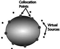
[image:2.595.248.346.473.554.2]in which p is the acoustic pressure, k=ω/c is the wavenumber, and c is the sound propagation velocity. To solve this equation, the Method of Fundamental Solutions (MFS) is used, following the scheme presented in Figure 1.
Figure 1 – Schematic representation of an MFS model for the acoustic domain Ω.
The MFS approximates the 3D pressure field within a given domain with a linear combination of fundamental solutions (Green’s Functions) of the governing differential equation – the Helmholtz equation (eq. (1)) [11]. The acoustic response at a generic point 𝑥 is then reproduced considering the effects of NS virtual sources located outside the interest domain, as expressed in equation (2).
𝑝(𝑥, 𝑘𝑎) = ∑ 𝐴𝑚𝐺3𝐷(𝑥, 𝑥0 (𝑚)
, 𝑘𝑎) 𝑁𝑆
𝑚=1
(2)
In this equation, 𝐺3𝐷(𝑥, 𝑥
0(𝑚), 𝑘𝑎) corresponds to the Green’s function of the sound pressure, which can be written as:
𝐺3𝐷(𝑥, 𝑥 0
(𝑚)
, 𝑘𝑎) =𝑒 −𝑖𝑘𝑎𝑟
𝑟 (3)
𝑘𝑎= 𝜔
𝑐 (4)
To complete this process, it is necessary to ascribe boundary conditions at the set of collocation points, resulting in a linear system of equations that allows determining the unknown amplitudes of the virtual sources 𝐴𝑚. So, and in case of prescription of normal velocities at the boundary (which in the present case are given by the dynamic response of the structure due to a dynamic impact force obtained from a 3D FEM model), the unknown amplitudes 𝐴𝑚 can be obtained by the following relation:
∑ [𝐴𝑚𝐻3𝐷(𝑥𝑃(𝑖), 𝑥0(𝑚), 𝑘𝑎, 𝑛⃗ )] = 𝑣𝑛,𝑖 𝑁𝑆
𝑚=1
(5)
In this expression, the Green’s function for particle velocities, 𝐻3𝐷(𝑥
𝑃(𝑖), 𝑥0(𝑚), 𝑘𝑎, 𝑛⃗ ), is defined in eq. (6):
𝐻3𝐷(𝑥
𝑃(𝑖), 𝑥0(𝑚), 𝑘𝑎, 𝑛⃗ ) =−𝑖𝜌𝜔1 (−𝑖𝑘𝑎𝑟 − 1)𝑒 −𝑖𝑘𝑎𝑟
𝑟2
∂r
∂𝑛⃗ (6)
where 𝑥𝑃(𝑖) corresponds to the coordinates of the collocation point i (with i=1,2,…,NP); 𝑛⃗ represents the direction along which the particle velocity is calculated; and 𝜌 and c are the medium density and sound propagation velocity, respectively. The prescribed velocities at each collocation point located at the boundary follow the condition:
𝑣𝑛,𝑖= − 1 i𝜌𝜔
∂p
∂𝑛⃗ (𝑥𝑖) (7)
In the case of absorbent boundaries, the condition that governs the determination of the amplitudes of the virtual sources is given by eq. (8), which is representative of the impedance condition established:
𝐻3𝐷(𝑥
𝑝, 𝑥0, 𝑘, 𝑛⃗ ) + 𝑍𝐺3𝐷(𝑥𝑝, 𝑥0, 𝑘) = 0 (8) where the parameter 𝑍 is defined as material impedance. This reflects a relationship between pressure and velocity, being expressed in function of the absorption coefficient, α, in accordance with the following expression:
𝑍 = −𝜌𝑐 (1 + √1 − α
1 − √1 − α) (9)
As described, the presented numerical model is used for an individualized treatment of the acoustic domain, where its compatibility with the structural domain is guaranteed by the prescribed normal velocity vector. This approach is usually defined as an uncoupled methodology or weak coupling. For current engineering applications, this vector can be obtained directly from a simple structural analysis performed a priori, as will be seen in the following sections.
3. EXPERIMENTAL SETUP
an opening in one of the lateral walls, with dimensions of 0.50 m x 0.50 m, which allows accessing its interior.
Figure 2 – External view of the small-sized acoustic chamber.
The main practical component of this work is the measurement of the sound pressure levels within the chamber induced by the application of a dynamic excitation on its exterior. Therefore, the sound levels perceived in the chamber interior are due to the interaction between the structure (elastodynamic problem) and the air (acoustic medium). Subsequently, the achieved experimental results are compared with numerical results provided by the numerical model.
4. STRUCTURAL MODEL
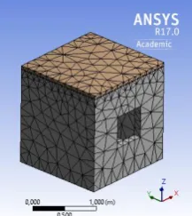
The experimental validation process follows a step by step approach. The structural response is achieved using the 3D FEM. For this purpose, software Ansys is used to compute mass and stiffness matrixes which are then used in a researchers’ “homemade” code to obtain the dynamic response of the system due to an impact. Taking into account the geometric characteristics of the structure previously described, the finite element model developed is illustrated in Figure 3. The elastomechanical properties of the different constituent elements were updated based on the results provided by a modal identification test developed. In order to calibrate the numerical model, a compatibilization between experimental and numerical vibration modes was made.
Figure 3 – Finite element model provided by Ansys software.
[image:4.595.244.353.544.666.2]a) b) Figure 4 – Hammer impact load: a) time-history; b) frequency content.
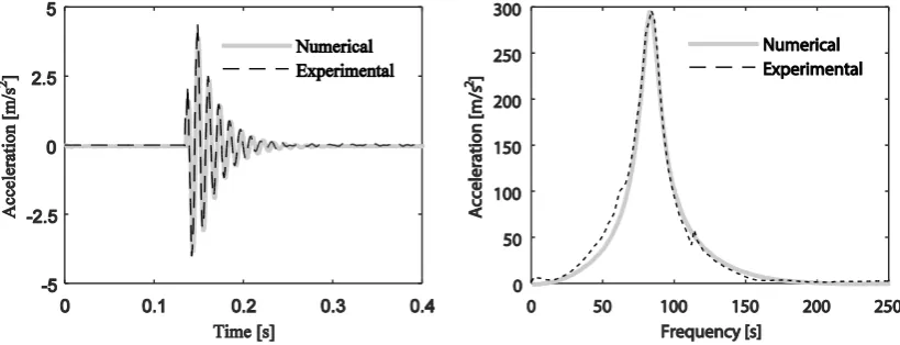
Considering the structural configuration of the acoustic chamber and the applied external excitation, the top slab is assumed as the structural element with the greatest relevance for the generation of re-radiated noise inside the structure. Therefore, an accelerometer was placed under the center of the top slab, in order to measure the vertical component of the acceleration of the structural response. Figure 5 shows the comparison of the experimental and numerical acceleration data records and respective frequency content. In general, there is a remarkable agreement between the results achieved, being this conclusion valid for both time domain and frequency domain registers.
Figure 5 – Structural response of the top slab (time-history and frequency acceleration content).
Analyzing in more detail the frequency content of the structural response, there is a discontinuity in the experimental curve for a frequency of around 113 Hz. The existence of such discontinuity is entirely related with the resonance verified in the acoustic field, as will be presented in the next section. Thus, the resonance of the acoustic medium induces the vibration of the structure. From a numerical point of view, such interaction is not verified once the numerical model implemented is based in an uncoupled approach, i.e., the acoustic domain is individually treated without taking into account the possible change in the vibration levels induced by the acoustic response. The highlighted aspects are in line with those reported in Colaço et al. [8], where the authors emphasize the existence of small discrepancies between the results from a fully coupled approach compared to those obtained by means of an uncoupled approach for frequencies around the resonance frequencies of the acoustic space.
[image:5.595.94.504.400.557.2]5. ACOUSTIC MODEL: EXPERIMENTAL VALIDATION
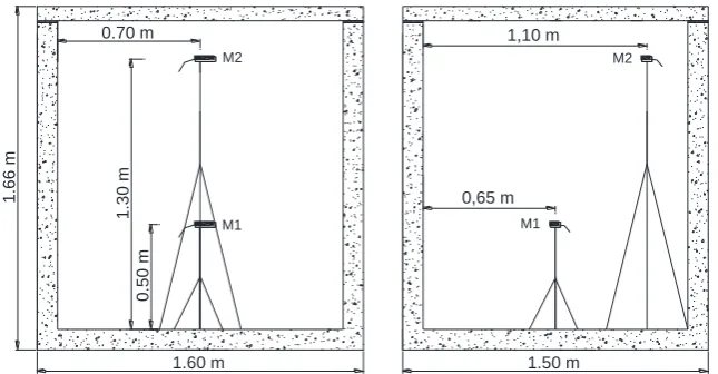
Following the objectives initially set, the last step of the current work is focused on the experimental validation of the numerical model implemented. Thus, the numerical acoustic response of the chamber is compared with the experimental measurements carried out at different locations within the acoustic space. The geometrical position of the microphones is shown in Figure 6.
Figure 6 – Schematic representation of the pressure measurement positions: lateral views.
[image:6.595.135.458.228.396.2]To apply the MFS procedure, a set of collocation points and virtual sources needs to defined. Obviously, collocation points are located along the acoustic domain boundary and virtual sources outside it. This set of points is schematically represented in Figure 7 for the visible faces of the domain. The number of virtual sources and distance between them and the collocation points is defined through an optimization procedure.
Figure 7 – Schematic representation of the collocation points (in blue) and virtual sources (in red) used in MFS model.
According to the implicit concepts to the numerical model, the boundary conditions are assigned at the collocation points. In this way and for the points located on the structural elements that bound the acoustic space, the two domains of analysis, structural and acoustic, are compatibilized by the imposition of the velocity field provided by the transient analysis. In relation to the collocation points located in the opening, these are treated as an absorbent boundary, being imposed a sound absorption coefficient α equal to 0.12, according to the sensitivity analyzes performed.
1
.6
6
m
1.60 m 1.50 m
0
.5
0
m
1
.3
0
m
0.70 m
0,65 m 1,10 m
M2
M1
M2
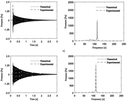
In terms of results, the time-history and frequency content of the acoustic response for the points illustrated in Figure 6 are depicted in Figure 8.
a)
[image:7.595.91.504.161.488.2]b)
Figure 8 – Acoustic response within the chamber (time-history and frequency content) registered at: a) Microphone M1; b) Microphone M2.
Similar to the results achieved for the structural response of the chamber, there is a remarkable agreement between experimental and numerical acoustic results. In fact, and despite small local perturbations, there is a perfect agreement between experimental and numerical results. In more detail, the acoustic response of the chamber is dominated by a resonance frequency around 113 Hz. This corresponds to a cavity resonance of the system and it is given in theoretical terms by the following expression:
𝑓𝑟𝑐=𝑐. 𝑛2𝑑 (10)
where 𝑐 corresponds to the sound propagation velocity, 𝑑 is the distance between two opposite walls and 𝑛 is an entire number (𝑛 = 1,2,3, … ). These resonances arise from stationary modes generated within the enclosed acoustic space between the top and bottom slabs. The second harmonic associated to the cavity resonance, for a frequency around 226 Hz, is also found in the previous curves, although with a reduced participation in the global acoustic response.
6. CONCLUSIONS
The experimental work carried out consisted in the excitation of a reduced size acoustic chamber through the application of an impulse with an instrumented hammer. Simultaneously, the structural and acoustic dynamic responses of the system were monitored by a set of accelerometers and microphones.
The case study was then modeled and the experimental data were compared with the numerical results, showing that the proposed numerical approach is efficient and accurate to predict re-radiated noise inside an enclosure.
ACKNOWLEDGEMENTS
This work was financially supported by: Project POCI‐01‐0145‐FEDER‐007457 ‐CONSTRUCT ‐ Institute of R&D in Structures and Construction and Project POCI‐01‐0145‐FEDER‐007633 both funded by FEDER funds through COMPETE2020 ‐ Programa Operacional Competitividade e Internacionalização (POCI) – and by national funds through FCT ‐ Fundação para a Ciência e a Tecnologia; Project PTDC/ECMCOM/1364/2014 and Individual Grant SFRH/BD/101044/2014. The authors are also sincerely grateful to European Commission for the financial sponsorship of H2020 MARIE SKŁODOWSKA‐CURIE RISE Project, Grant No. 691135 “RISEN: Rail Infrastructure Systems Engineering Network”.
REFERENCES
1. Smith, M.G., I. Croy, M. Ögren, and K. Persson Waye, (2013), On the Influence of Freight Trains on Humans: A Laboratory Investigation of the Impact of Nocturnal Low Frequency Vibration and Noise on Sleep and Heart Rate.PLoS ONE. 8(2): p. e55829.
2. Croy, I., M.G. Smith, and K.P. Waye, (2013), Effects of train noise and vibration on human heart rate during sleep: An experimental study.BMJ Open. 3(5).
3. Smith, M.G., I. Croy, M. Ögren, O. Hammar, E. Lindberg, and K. Persson Waye, (2017), Physiological effects of railway vibration and noise on sleep. Journal of the Acoustical Society of America. 141(5): p. 3262-3269.
4. Woodcock, J., G. Sica, E. Peris, C. Sharp, A.T. Moorhouse, and D.C. Waddington, (2016), Quantification of the effects of audible rattle and source type on the human response to environmental vibration.Journal of the Acoustical Society of America. 139(3): p. 1225-1234.
5. Nagy, A.B., P. Fiala, F. Márki, F. Augusztinovicz, G. Degrande, S. Jacobs, and D. Brassenx, (2006), Prediction of interior noise in buildings generated by underground rail traffic.Journal of Sound and Vibration. 293(3-5): p. 680-690.
6. Fiala, P., G. Degrande, and F. Augusztinovicz, (2007), Numerical modelling of ground-borne noise and vibration in buildings due to surface rail traffic. Journal of Sound and Vibration. 301(3–5): p. 718-738.
7. Romero, A., P. Galvín, J. António, J. Domínguez, and A. Tadeu, (2017), Modelling of acoustic and elastic wave propagation from underground structures using a 2.5D BEM-FEM approach.Engineering Analysis with Boundary Elements. 76: p. 26-39.
8. Colaço, A., P. Alves Costa, P. Amado-Mendes, and L. Godinho, (2017), Prediction of Vibrations and Reradiated Noise Due to Railway Traffic: A Comprehensive Hybrid Model Based on a Finite Element Method and Method of Fundamental Solutions Approach. Journal of Vibration and Acoustics. 139(6): p. 061009-061009-10.
10. Marburg, S., Computational Acoustics of Noise Propagation in Fluids - Finite and Boundary Element Methods. 2008: Springer-Verlag Berlin Heidelberg.