FIRST SUGGESTIONS FOR THE IMPROVEMENT OF ACCORDION REEDS
PACS REFERENCE: 4375.Pq
Llanos-Vázquez, R.1; Alonso-Moral, J.2; Elejalde-García, M.J.1; Macho-Stadler, E.1 1
Dpto. Física Aplicada 1. Escuela Superior de Ingenieros. UPV/EHU. Address: Alameda de Urquijo s.n., 48013 Bilbao, Spain.
Tel: 34-946014256. Fax: 34-946014178. E-mail: [email protected] 2
Conservatorio Superior de Música Juan Crisóstomo de Arriaga Address: General Concha 20, 48010 Bilbao, Spain.
Tel: 34-944412136. Fax: 34-946014178. E-mail: [email protected]
ABSTRACT
The purpose of this study is to give critical insight and needed specificity to the accordion reed making and tuning process. We present the acoustical background of the reed behaviour and its sensitivity to selected shape changes.
INTRODUCTION
The accordion reeds have different shapes, some of them are loaded with a little mass at their free end, and they are worn out to adjust the tuning, etc. All these facts complicate the achievement of a theoretical model that accurately describes the vibration behaviour of the mentioned reeds. In our work, we try to develop a physical knowledge useful in the elaboration and tuning adjustments of the reeds of the instrument. Using a perturbation approach, we research the possibilities to control the frequencies, vibration amplitude and quality factor of the resonance modes, that is, the parameters that influence in an essential way in the production of accordion tones. We consider the reed as a thin clamped-free bar.
In this paper, by slightly perturbing the mass and the effective stiffness of a clamped-free stainless steel bar we investigate the frequency change of the first resonance mode, and the shape of the complete vibration mode.
BACKGROUND THEORY
Normal Modes of Transverse Vibration of a Clamped-Free Bar
Let us consider a perfectly rectangular and homogeneous metallic thin bar of length L, width b, thickness h, and mass M. In spite of the transverse vibration, there exists a neutral axis whose length remains invariable. We will take a coordinate x that measures the position along the bar and a coordinate y that measures its transverse deformation from the neutral axis. The equation that describes the propagation of transverse vibrations through this bar is
4 4 2 2 2 2
t y c t
y
∂ ∂ κ − = ∂ ∂
Here,
12 h2 =
κ represents the radius of gyration of the transverse section of the bar and
ρ = Y
c , where Y is the Young’s modulus and ρ is the density of the bar.
The solution of this equation is
) v x sin D v x cos C v x sinh B v x cosh A )( t cos( ) t ; x (
y = ω +Φ ω + ω + ω + ω (2)
where A, B, C and D are real constants, which will be fixed by the boundary conditions, and κ
ω = c
v .
We can consider an accordion reed as a thin bar clamped at one end (x=0) and with the other end free (x=L). Thus, we have y=0, 0
x y = ∂ ∂
at the clamped end and 0 x y 2 2 = ∂ ∂ , 0 x y 3 3 = ∂ ∂ at the free end.
Clamped end conditions simplify the general solution to
ω − ω + ω − ω Φ + ω = v x sin v x sinh B v x cos v x cosh A ) t cos( ) t ; x (
y (3)
while the free end conditions imply the following two additional conditions
v L sin v L sinh v L cos v L cosh A B ω + ω ω + ω −
= and
v L cos v L cosh v L sin v L sinh A B ω + ω ω − ω −
= (4)
which can be reduced to
v 2 L tan v 2 L
cotω =± ω . The solutions for the frequencies of the normal
modes of vibration are (1.194;2.988;5;7...) 4
v 2
L = π ω
. Using v= ωcκ, the frequencies are
...) 7 ; 5 ; 988 . 2 ; 194 . 1 ( L 8 c
f 2 2 2 2
2 κ π
= (5)
So, the characteristic function corresponding to the frequency fn will be given by
ω − ω + ω − ω = v x sin v x sinh B v x cos v x cosh A ) x (
yn n n (6)
with v L sin v L sinh v L cos v L cosh A Bn n
ω + ω ω + ω −
= and can be orthonormalized
mn n
L
0ym(x)y (x)dx=Lδ
∫
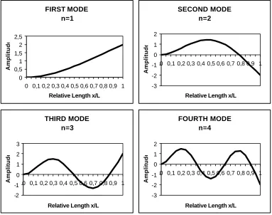
(7)The shapes of the first four transverse modes of vibration are shown in Figure 1.
Figure 1. Normal modes of transverse vibration of a clamped-free bar.
If an oscillator of mass m and stiffness constant k has a resonance frequency f given by
m k 2
1 f
π
= , then the characteristic frequency of the n-th normal mode of a vibrating system can
take an analogous expression
ef n
ef n
n
M S 2
1 f
π
= , where we have defined the effective stiffness
ef
S and the effective mass Mef of the n-th normal mode. In the case of transverse oscillations of a clamped-free bar that is excited at a point x it can be shown that the effective stiffness 0 and mass are given by:
) x ( y
dx x
) x ( y
12 Ybh S
0 2 n L
0
2
2 n 2
3 ef
n
∫
∂ ∂
= and
) x ( y
dx ) x ( y L M M
0 2 n L
0 2 n ef
n =
∫
(8)Perturbation Approach to Evaluate the Normal Modes
If we place a small mass centred at a point x1 of the bar the frequency of the normal modes changes. We can interpret this variation as caused by the variations in the effective mass and rigidity of the composed (bar plus mass) system.
We denominate M'nef the effective mass of the system when we add a small mass m. We will suppose that this loading mass is so little that the normal modes and the effective stiffness remain invariable. We call fn the frequency of the n-th vibration mode of the system without the loading mass, and f'n the frequency of the n-th vibration mode of the system with the loading mass; the relation between both frequencies will be:
FIRST MODE n=1
0 0,5 1 1,5 2 2,5
0 0,1 0,2 0,3 0,4 0,5 0,6 0,7 0,8 0,9 1
Relative Length x/L
Amplitude
SECOND MODE n=2
-3 -2 -1 0 1 2
0 0,1 0,2 0,3 0,4 0,5 0,6 0,7 0,8 0,9 1
Relative Length x/L
Amplitude
THIRD MODE n=3
-2 -1 0 1 2 3
0 0,1 0,2 0,3 0,4 0,5 0,6 0,7 0,8 0,9 1
Relative Length x/L
Amplitude
FOURTH MODE n=4
-3 -2 -1 0 1 2
0 0,1 0,2 0,3 0,4 0,5 0,6 0,7 0,8 0,9 1
Relative Length x/L
ef n ef n ef n ef n ef n ef n ef n ef n ef n ef n ef n n n M M 1 M M S M S ' M S M S ' f f ∆ + = ∆ + =
= (9)
But, the expression of the modified effective mass can also be written as
ef n ef n 0 2 n 1 2 n ef n 0 2 n L 0 1 2 n 2 n ef
n m M M
) x ( y ) x ( y M ) x ( y ) x ( my dx ) x ( y L M '
M = + = +∆
+
=
∫
(10)Using Eq. (7), (8), (9) and (10) we deduce the following relationship between frequencies
M m ) x ( y 1 M mL dx ) x ( y ) x ( y 1 ) x ( y dx ) x ( y L M m ) x ( y ) x ( y 1 M M 1 ' f f 1 2 n L 0 2 n 1 2 n 0 2 n L 0 2 n 0 2 n 1 2 n ef n ef n n
n = +∆ = + = + = +
∫
∫
(11)From this relation we can find the following expression for the function y evaluated at n x (the 1 point where the concentrated mass has been placed at)
m M 1 ' f f ) x ( y 2 2 1
n
−
= (12)
Therefore, if we know the values of the masses of the bar and the loading mass, M and m, and we measure the frequencies f and 'f , we will be able to calculate the value of the n-th mode of vibration at the point of placement of the mass. If we go moving the loading mass, we will be able to obtain the shape of the complete vibration mode. Then, we will be able to evaluate the validity of this perturbation approach by comparison of the obtained expression for yn(x1) with that of the theoretically obtained one in accordance to the equation (6) (we will denote this last value y n(x1)
teor
).
EXPERIMENTS
Experimental conditions
For the experiments, we used a stainless steel bar, of the following characteristics: width b = 29.75x10⁻³ m, thickness h = 1.5x10⁻³ m, and density ρ = 7900.8 kg/m3
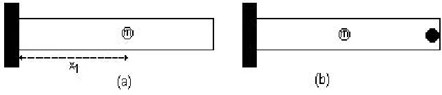
[image:4.596.133.454.662.731.2]We carried out two series of experiments with clamped-free end boundary conditions, simulating this way the boundary conditions of the accordion reeds (See Figure 2).
In the first series, the vibrating length of the bar was L = 189x10-3 m. In the second series, the bar was loaded with a concentrated mass of 8.48x10⁻³ kg (this added mass had a diameter of 14 mm, and its edge coincided with the free end of the bar). In order to normalise the frequency of the fundamental mode with that obtained in the first series, the vibrating length of the bar was set to 178x10-3 m.
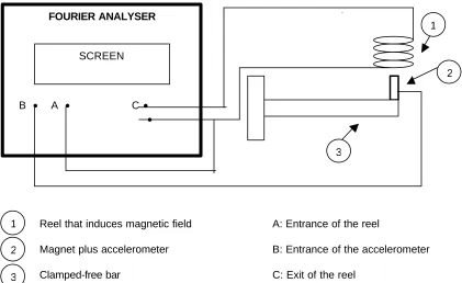
The measurements of frequency, vibration levels and quality factors were carried out with a “2034 Brüel &Kjær Dual Channel Signal Analyser”, and a miniature 4374 accelerometer of the same company. The experimental device is shown in Figure 3.
Experimental device
Reel that induces magnetic field A: Entrance of the reel
[image:5.596.84.505.217.475.2]Magnet plus accelerometer B: Entrance of the accelerometer Clamped-free bar C: Exit of the reel
Figure 3. Scheme of the experimental setting
A generator added to the analyser produces an alternating current in the reel (with exit C) that creates a magnetic field. This magnetic field acts on the magnet, which in turn produces an excitement force on the clamped-free bar. Exciting with the appropriate frequency band of “white noise” signal, the bar vibrates, reaching its vibration maximum at the resonance frequency. We obtain the input admittance of the bar as a function of the frequency by collecting the vibrations with the accelerometer (entrance B), processing them with the analyser, and then dividing by the intensity of the reel (entrance A). This device allows measuring the frequency of resonance, vibration levels, quality factor of the resonance modes and phase differences between the exciting force and the vibration speed of the bar. This method of measurement of input admittance is similar to that used by Erik Jansson and one of the authors, in the Royal Institute of Technology of Stockholm.
Experimental process
With a bandwidth of 50 Hz and 800 lines in the analyser, our precision was of + 0,0625 Hz; the high reproducibility of our measurements indicates that this value seems to measure the experimental error.
In order to compare the expected results from the vibration theoretical model of a clamped-free bar with the experimental variations of frequency, some measurements were carried out in both series. A loading mass m = 3x10⁻³ kg was placed at the free end of the bar and, starting from there, it was moved toward the fixed end by 20 mm steps.
1 2 3
2
FOURIER ANALYSER
B • A • C • •
SCREEN
1
RESULTS
Comparing the values yn(x1) and y n(x1) teor
we obtain that the agreement is reasonable when the loading mass is close to the free end (x=L) of the bar; nevertheless, when the loading mass position comes closer to the clamped end (x=0), yn(x1) is bigger than the expected theoretical value.
As it could be supposed, when placing the loading mass, the frequencies of resonance are smaller than those obtained when no mass is placed, since the effective mass of the system increases. However, we observe that when the loading mass is placed very close to the clamped end, the measured frequency 'f is bigger than the frequency f of the bar without the loading mass. It is because the effective stiffness of the system increases and the oscillations become quicker. We could take advantage of this effect to increase the frequency of a reed by means of the application, for example, of a small tin layer close to the clamped end, instead of the classic procedure of removing weight from the free end by filing the reed of. Evidently, before opting for this procedure it would be necessary to compare the timbres and responses of both types of reed.
CONCLUSIONS-APPLICATIONS
• This first approach shows that by means of perturbations of small masses, it is possible to carry out a description of the vibration pattern of the bars. The results can be applied to the accordion reeds.
• The perturbation theory can help the manufacturer and tuner of reeds in their corresponding activities.
• This work suggests that the manufacturers and tuners can use more degrees of freedom than the usual ones, so that a number of applications for the improvement of the reeds seem to be opened. For example, to increase the frequency, it is possible to use an increase of the rigidity near the clamped end, and not only the usual procedure of removing mass from the free end.
• In the second experiment, the big concentrated mass, fixed at the free end of the bar, changes noticeably the vibration pattern, making the amplitude lower than that of the equivalent bar of the first experiment. Nevertheless, the same perturbation approach of the first experiment can be used, placing a little concentrated mass every 20 mm starting from the free end. This lower amplitude can be one of the reasons for the preference of long reeds without loading mass to shorter reeds with concentrated mass at their free ends. • A theoretical and experimental physic control of the perturbations of mass and rigidity
seems to give a suitable knowledge for the necessary technical-handmade activity in the precise adjustments that the accordion reeds need.
• As a future research, we set out a more detailed vibration analysis for the first partial and the upper ones, as well as the study of the influence of the design and of the perturbations in the timbre of the instrument.
• Our calculations, based on the experimental measurements, point out that the quality factor (Q) increases at least a 10% in the second series, that is, in that of the shortened bar with the added big mass at its free end area. Nevertheless, more experimental evidence is necessary to reach decisive conclusions as well as for the development of the corresponding theoretical model.
REFERENCES
1
P. M. Morse and K. U. Ingard, Theoretical Acoustics. (Mc Graw Hill, Princeton, 1968). 2