Body part detection using a low cost depth camera
48
0
0
Texto completo
(2) Instituto Tecnológico y de Estudios Superiores de Monterrey Campus Estado de México Escuela de Ingeniería y Tecnologías de Información Programa de Graduados. Los miembros del comité de tesis recomendamos que la presente tesis de Christian Jesús Arzate Cruz sea aceptada como requisito parcial para obtener el grado académico de Maestro en Ciencias Computacionales, especialidad en:. Gráficas Computacionales. Comité de tesis:. Dr.Isaac Juan Rudomín Goldberg Asesor de la tesis. Dr.Benjamín Hernández Arreguín. Dr.Miguel Gonzales Mendoza. Sinodal. Sinodal. Dr. ~iguel Gonzales Mendoza Director del Programa de Graduados. Noviembre de 2011.
(3) Contents. .IV. Reconocimientos Resumen. V. List of Figures Chapter 1 Introduction 1.1 J ustification . . . .. Vlll. ............................. 1 2. Chapter 2 Our Methods. 5. Chapter 3 Pedestrian Detection System 3.1 State of the Art . . . . . . . . . . . . . 3.2 System Description . . . . . . . . . . . 3.3 Experimental Results for Pedestrian Detection. 6 6. 8 14. Chapter 4 Hand, Fingertip and Face Detection System 4.1 State of the Art . . . . . . . . . . . . . 4.1.1 Hand Detection Techniques . . 4.1.2 Fingertip Detection Techniques 4.1.3 Face Detection Techniques . . . 4.2 Hand Detection System Description .. 4.3 Fingertip Detection System Description . 4.4 Face Detection System Description . . . 4.5 Experimental Results for Hand, Fingertip and Face Detection. 19. Chapter 5 Conclusions and Future Work. 31. Appendix A Growing Region CUDA Kernel. 32. Appendix B Segmentation by Depth CUDAKernel. 35. Appendix C Universal Filter CUDA Kernel. 37. Vl. 19 19 19. 20 21 25 27. 28.
(4) Bibliography. 40. vii.
(5) List of Figures. 3.1 3.2 3.3 3.4 3.5. 8 10 11 12. 3.6 3. 7 3.8 3.9. Example lmages our First Test Elimination Processes . . . . . . . . . . . . . . . . . . . . Example Images of Dense Crowds We Are Dealing With Crowd Detection Flowchart . . . . . . . . . . . . . . . . . . . . . . . . (1) Input lmage; (2)Derivative Step Output; (3)Layers Extraction Step Output; (4) Detection Step Output . . . . . . . . . . . . . . . . . Results Examples of Each Step of Pedestrian Detection Algorithm Incorrcct Dctcction Examplc . Similar Work . . . . Application Example . . . . .. 4.1 4.2 4.3 4.4 4.5 4.6 4.7. Limitations of the First Approach of Hand Detection Algorithm Hand Detection Algorithm Flowchart . . . Hand Detection Outcomes . . . . . . . . . Fingertips Detection Algorithm Flowchart Fingertip Detection Outcomes . . . . Face Detection Algorithm Flowchart Face Detection Outcomes . . . . . . .. 21 22 23 25 26 28 29. viii. 12 15 16 17 18.
(6) Chapter 1. Introduction. Computer vision has many fields of application and recently is more widely used because digital RGB carneras, depth cameras and stereoscopic vision systems are cheap and extensively available as an embedded component in smart phones, security systems, cars, intelligent buildings or video games consoles. Depth data allows a much better analysis of the environment. It can be seen, for example, on safety systems of cars improved by stereoscopic vision systems. Of all fields that benefit from 3D image processing we saw a greater opportunity to innovate on crowd behavior detection and data driven crowd simulation systems, and detection of hands, fingers, and faces. In following sections we'll explain in detail our motivation to work on these topics. Research on virtual crowd simulation has become more and more popular in recent years. Different researchers have focused on different research fields. For example, in the film and game industry, they often focus on how to simulate the intelligent behaviors and visual feelings of real crowds. This is made with the objective of giving the audience or video gamers a better and more immersive experiencc. Thcrc are a lot of more applications where we need to simulate realistic crowd behaviors, designing and evaluating the degree of security of a building is a good example. There are a lot of methods for developing behaviors for crowds. We can separate all these techniques in two big branches; rule based 1 and data driven 2 3. Due to thc complcxity of the individual and collcctivc bchavior of pedestrians in a crowd, rule based crowd simulation algorithms don't perform as well as it is needed for the aforementioned applications. Besides, rule based approaches need to be finely tuned to achieve a particular behavior, this is difficult to define and often requires a lot of trial an error. Given a new situation, a new set of rules needs to be defined. Data driven approach creates very realistic results but requires a lot of work. Most of these tcchniques are bascd in data acquircd frorn video rccorders from spccific real crowds. Commonly, data used for these rnethods are rnetrics, such as position, velocity and acceleration, for each individual character in the crowd. Because of the difficulty to 1.
(7) get these metrics automatically, they manually acquire the data viewing crowd videos frame by frarne. Nune of the reviewed articles irnplernented a cornputer vision algorithm for data acquisition. All data driven articles manually reviewed, identify and track pedestrians in a crowd. Automatic pedestrian detection and tracking is a well-studied problem in computer vision research, but the current solutions are only able to track a few pedestrians. Inter-object occlusion, self-occlusion, reflections, and shadows are sorne of the factors making automatic crowd detection and tracking difficult. The Pedestrian recognition problem is especially difficult when we work with large, unstructured and dense crowds. We have reviewed various novelty articles about these topic and they have problems for detecting people when they are partially or fully occludcd. Computer vision is a powerful interface for computers, because is more natural and enjoyable for people to use body movement or hand gestures [34]. Current prices of computer vision systems are cheap enough to replace interfaces such as buttons and joysticks. At the same time, interaction without the use of any kind of additional devices is still open and difficult. Hand, fingertips and face detection are preliminary steps to a numbcr of HCI applications. Thc major complications that rcscarchcrs havc found when they want to detect people's hands, fingertips or faces are: variety in people's looks and poses, lighting conditions, reflection and shadows. Depth cameras simplify many of these complications; they are insensitive to illumination changes thereby providing geometry information in a direct manner.. 1.1. J ustification. There are a variety of applications that require knowing the behavior of a crowd. In the introduction we mentioned sorne examples, which include movies and video games. If you look at today's films, from the point of view of special effects, it is easy to see that most of the characters shown on screen are computer generated crowds. An example in which one can clearly see this is in the movies of The Lord of the Rings. In battlcs thcy showcd thousands of soldicrs. Whcn crowds are so largc, assigning each character its position in the scene frame by frame by hand is an almost impossible task. In these cases the characters are endowed with a behavior and a given goal, so they determine their position in each frame of the movie. In this particular case is very important that crowd behavior is very realistic in order to gain credibility with the audience.. 2.
(8) Another application is the development of surveillance systems based on security cameras. Currently, based security systems cameras simply just record a static particular area. This is a problem because if you get to submit a crime suspect ends often occluded by other people and it is impossible to recognize. If we had a pedestrian recognition system able to aualyse their behavior we could identify people who act out of the ordinary. Having identified a prospective offender you may take high resolution pictures of his face to be easily identifiable. The area of urban design for safer structures could be greatly benefited if we had realistic behavior on how people behave when an incident inside the building that forces them to leave the building as quickly as possible. Having this knowledge could build virtual models of the building to be built and run a simulation of characters endowed with thc appropriatc bchavior may find areas for improvcmcnt in sccurity issues and assess the building befare it is built. The first step to get realistic behaviors is to obtain data from real crowds. To achieve this task we need to develop a robust algoritlun based 011 computer vision to detect pedestrians in dense crowds. Hand gcsturcs are a natural way of communication which is commonly used to communicative (Sign Language recognition) and manipulative (controlling robots without any physical contact between human and computer). Face detection also is important for HCI application because people's gaze can be used to control robots ora video game, for example. The first steps to recognize hand gestures and gaze direction are: detect hands, and detect fingertips, and detect faces. To achieve our goal we need to develop a robust algorithm based on computer vision to detect hands, fingertips, and faces. We have the following objectives: • lmplement and evaluate a robust algorithm that detects pedestrians in dense crowds in real time. • Implement and evaluate a robust algorithm that detects hands in real time. • lmplement and evaluate a robust algorithm that detects fingertips in real time. • lmplement and evaluate a robust algorithm that detects faces in real time. In order to obtain a good algorithm capable of detecting pedestrians in dense crows it needs to have the following characteristics:. 3.
(9) • InsensitivP to lighting conditions, reflection and shadows. • Vnaffcctcd by crowds' dcnsity • The algorithm have to run in real time • The algorithm's performance should be independent of crowds' density In arder to obtain a good algorithm capable of detecting hand, fingertips and faces it needs to have the following characteristics:. • Insensitive to lighting conditions, reflection and shadows. • Thc algorithm havc to run in real time. 4.
(10) Chapter 2. Our Methods. In next sections we will describe our methods. Our work is aimed to detect pedestrians in a crowd, hands, fingertips and faces using a depth map of the scene which uses an algorithm running in real time. In order to achieve our goal, we'll use a depth camera instead of a traditional RGB camera. We chose depth cameras because they simplify the whole stage of the system; they are insensitive to illumination changes thereby providing geometry information in a direct manner. Details of the proposed systems are dcscribcd bclow.. 5.
(11) Chapter 3. Pedestrian Detection System. 3.1. State of the Art. The segmentation and tracking of pedestrians in video sequences is very important as there are a lot of tasks in which people is the main subject of study. At the same time, pedestrian recognition is still open and especially difficult when we work with dense crowds. The major complications we find are: variety in people's looks and poses, lighting conditions, reflection, background elimination, shadows and occlusion between different objects. Many traditional 20 computer vision algorithms have been developed to recognize individual pedestrians within crowds. Most of the current approaches use static video cameras and recognize people based on their silhouette, the texture of their clothes, face recognition, color histogram or object recognition algorithms. In the literature we can find several manners to detect people. For instance, in [32, 1, 22] we can see the use of contour analysis, other approaches use object recognition algorithms [38], depth data [36, 35, 26, 25, 37], or model-based matching [26]. In arder to increase accuracy, sorne systems use a combination of several of the aforementioned techniques. Approaches employing rnodel-Lmsed representations can be further categorized as shape based and intensity level based. Chern-Horng Sim et al. [8] proposed a method to improve the detection rate of a local detector for individuals within dense crowds. Their approach relies on color information in the detected window and a supervised learned cascade of boosted classifiers working with Haar-like fcatures. For the training process 8032 positive and 6816 negative samples were used. In [39] Chengbin Zeng and Huadong Ma. implemented an algorithm that combines the multilevel HOG (Histograms of Oriented Gradients) with the multilevel Local Binary Pattern (LBP) as the feature set for detecting the head and shoulders of peo-. 6.
(12) ple. For the training process 2000 positive and GOOO m•gative samples were used. This rnethod was nut extended tu densely cruwded scenes due Lo oc:clusiuns. Hiroaki Ando aud Hiru11ubu Fujiyoshi [3] have achieved human-area segmentation requiring no background image by using chamfer matching to match the results of human detection using Real AdaBoost with silhouette images. Their proposed method also enables segmentation accuracy to be improved by selecting silhouette images similar to the matching target beforehand based on response values from weak classifiers in Real AdaBoost. The real AdaBoost response values of the detected areas and the silhouette images are compared to select the silhouette image that is most similar to the human in the detected area. Finally, chamfer matching is performed on the selected silhouette image and the human detection result area to accomplish the human area segmentation. Ion Giosan, Sergiu Nedevschi and Silviu Bota [17] present a system that uses pedestrian full body exterior edges and a matching technique for the detection of people within a scene. This approach computes the similarity between the neighborhood of each pixel and all the pixels of the objects' areas from the image performing noise reduction and preserving the original image. The method used to remove the inner object edges and noise is !"JL Means. The three above cited papers are computationally heavy and need a lot of processing power and an enorrnous amount of offline training time. It is because templatebased search, despite its hierarchical structure, represents a computationally intensive operation when performing a dense sean across the image. Although their detection rate is high, so is their false positive rate. Thc tcchniquc dcscribcd in [19] is based on pattcrn matching. To build the pedestrian model is the first step in this method. The pedestrian model captures the most important features of a pedestrian by finding strong convex shapes. To detect these shapes they use the Hough Transformation method. Then, Pedestrian recognition is carried out by matchiug the local couvex shape descriptors of au input image with the previously learned pedestrian model. This detection system correctly finds people at a rate of 98.8%. Depth information has been utilized for pedestrian detection in recent years. Sorne approaches use only depth iuformation to achieve their goal [12] and sorne other depthbased pedestrian detection methods use depth information on occlusion analysis [36], better foreground aud background segmentation [35, 26, 25] , and enhance objects' shapes [37, 18]. 7.
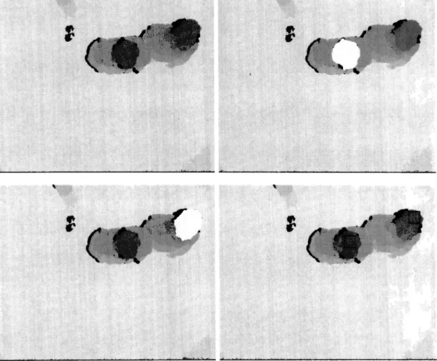
(13) For example, Philip Kelly et al. in [26] develop a technique based on the use of depth information, ground plane estimation and basic human biometric information. Their method starts by removing depth points that are outside a predefined search space. Then the remaining regions are compared to a cylinder based biometric model of a pedestrian; this model assumes pedestrians are standing upright. Depending on the outcome of this comparison, the region is either split into multiple pedestrians, left intact or removed. When crowd density is high, this approach fails in segmenting people accurately. This problem can be attributed to the merging of pedestrians other pedestrians.. 3.2. System Description. Before start with the method we propose in this paper, we will explain the first approach that was tested and discarded. Below we explain in detail the first approach we test.. Figure 3.1: Example Images our First Test. This first method is ha.sed on a growing region algorithm and the premise the closest point from pedestrians' blobs and the depth camera is a head. With this premise can be easily detected pedestrians if they do not touch each other. An example of a well detected person in Figure3.l(a) and bad segmented pedestrians 3.l(a). To tackle this limitation we implemented the growing region algorithm. Pseudo code for this algorithm is next:. 8.
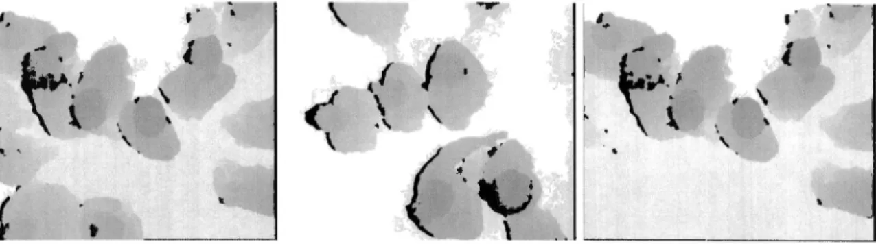
(14) Initialization: Label seed points according to their initial grouping. Put neighbours of seed points (the initial T) in the SSL.. Region Growing: While SSL is not empty do Remove first pixel y from the SSL. Test the neighbours of this point: if all neighbours of y which are already labelled have the same label than Set y to this label. Update running mean of corresponding region. Add neighbours of y which are neither already set nor already in the SSL to the SSL according to their value of delta. else Flag y with the boundary label. The growing region algorithm is seeded by the closest pixel of each blob, in this way we eliminate a pedestrian head. If more pixels remains in the blob we find the closest pixel to the camera, and again, we feed our growing region algorithm in order to climinate another region. We determine if this new climinatcd region is a hcad or not based on its features: blobW idth, blobH eight and aspectRatip. Also we check if there are a previously eliminated area covering the new. If the new eliminated area is covered by an old one, it is discarded as a head. This processes is repeated for each blob until no more pixels remains or a number of iterations threshold is reached. In Figure 3.2(a) shows the elimination processes for tow people touching one another. This method proved to be robust and handle situations of dense crowds. The only problem with it was its performance, it ran at 5 FPS. It algorithm could not fulfil our objectives because we want an algorithm running in real time. To remedy the poor performance of our algorithm we coded the growing region algorithm in CUDA. Our first approach was based 011 substituting the most heavy f or cycle (when checking all ncighbours) for a CUDA kernel. Unfortunatcly this tcchniquc did not spccd up our processes, CPU and CPU irnplementations had a very similar performance. We realized we have to cornpletely change the structure of the growing region algorithm if we want to improve its performance in the GPU. For new approach for the growing regions algorithm in CUDA we used a thread per pixel instead of using a tread per neighbour. In this way we take advantage of all 9.
(15) '. '. Figure 3.2: Elimination Processes. 10.
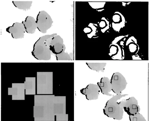
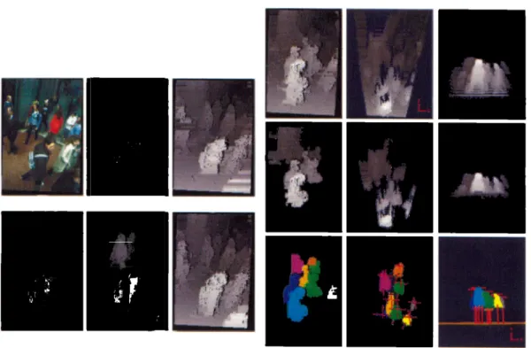
(16) threads in blocks and we do all process at the same time. This algorithm can even grow rnultiple regions at the same time. Thanks to this irnprovernent we could use the growing region algorithm far real time applications. In The Appendix Section is shown this CUDA kernel.~ow we will explain the definitive teclmique far detecting pedestrians. In the following we describe our method far detecting pedestrians. First we will describe the hardware used and camera set up, then we explain the different steps in our definitive method and the results achieved with this method.. .. '·. . '. -. ~·\. l " ~ \. \. '. -r'. \ ({. I. < (·:~ \.,. '. '·. -. ". ~~:' '. .. •. . '. \.. " ~ \. \. '. Figure 3.3: Example Images of Dense Crowds We Are Dealing With. Our system consists of a low cost depth camera which provides a 640x480 depth map at 30 FPS. Objects as far as 4 m cannot be seen by this sensor. To maximize the area that our sensor is able to see, we positioned it on a birds-eye view approximately 3.5 meters above the ground. We recorded dense crowds in real situations, far example: waiting far an elevator, thronging into a narrow passage or watching a performance. Ali videos were taken indoors because our depth camera does not work properly outdoors. The maxirnum number of people on the scene was 12 with a density of about 4 pedestrians per square meter. Figure 3.2 shows sample images of the dense crowds that we are dealing with. Our approach relies on finding pedestrians' heads in depth irnages. A key component far finding hcads in dcpth imagcs is the applying of a dcrivativc to the depth map. It is vital because contour is a strong feature far pedestrian detection [6]. Using contours instead intensity eliminates most of the problems that could cause detection errors like illumination conditions, reflections, background elimination and shadows. Likewise, it is important because to suppress absolute depth information, thus allowing the scene to be treated as a conventional 20 image, which is easier to process with standard computer vision techniques [9]. The algorithm has three rnain stages, training, segmentation and matching stages Figure 3.4. In training stage scenes containing pedestrians are manually segmented. 11.
(17) Segmentation Stage Background Removal. Matching Stage. Contour Extraction. [. ). Training Stage. Connected Components. Layers Extraction. ----------------• Figure 3.4: Crowd Detection Flowchart. <' \. J / \.,. \. ..... \ º_)._. Figure 3.5: (1) Input Image; (2)Derivative Step Output; (3)Layers Extraction Step Output; (4) Detection Step Output. 12.
(18) This segrnentation is aimed to eliminate all pixels except those belonging to pedestrians' head. Then the rnust significant eigen values of heads' blobs are saved and a generic head model are learned from this data. The Segmentation stage is intended to eliminate background pixels and separate pedestrians into depth layers. In Figure 3.5(a) we can see a pedestrian correctly separated in two layers, one for the head and another for the rest of the body. Layers that are not covered by others are marked as likely heads. In the matching stage a correlation metric is calculated between likely heads and the previously learned head models. Depending on the outcome of this match, layers are recognized either as a head or not. Details are described below. Our head model is simplistic with the purpose of avoiding detection mistakes caused by variety in people's look and pose. Matching stagc is also bcncfited because its computational costs are minimized. Our head is modelled as a rectangle with an aspect ratio of about 1.4 and eigen values between meanH ead - ST D and meanH ead + ST D pixels. In Background Removal step pixels are outside a predefined search space are removed. The search space was manually defined in order to eliminate ground and wall planes. Then, in the Contour Extraction stcp, we take a dcpth map of a scene with only foreground pixels and compute the absolute depth derivative in X and Y axes using a 9x9 pixel window. This outcome is then compared to a fixed threshold in arder to binarize the image. The outcome of the Contour Extraction step is an image where black pixels represent abrupt changes in depth and the white ones flat regions (Figure 3.5(a)). It is important to notice depth derivative separates pedestrians' body into severa! blobs. Usually these blobs correspond to head's blob, shoulders' blob and legs' blob. A correct blob separation depends on the threshold binarizing derivative images. Regardless of the position and height of pedestrians, the derivative profile is mostly invariant, so once a correct binarization threshold is found it works for all depth conditions. The Connected Components step applies a labelling algorithm to the Contour Extraction outcome. It is aimed to extract blob's features. The features we consider important are: width (blobW), height (blobH), aspcct ratio (aspectR), and dcpth value which correspond to the closest pixel to camera (blobMinVal). This value is extracted from the original depth map. The Layers Extraction step is used to paint a !ayer for each blob found in the previous process. Put simply, we use blobs' features to create rectangles of size blobW + 13.
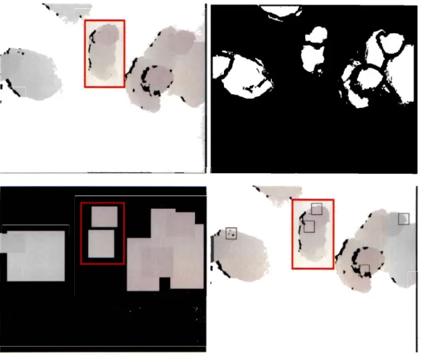
(19) dilatenxblobH + dilaten ancl an intensity level of blobM in V al. The Dilating of layers by the Dilaten assures layers corresponding to shoulders will be covered by head layers, dilaten is fixed to 10% of meanH ead. Therefore the Layers Extraction stage is aimed to determine which layers are covered by other and which are not. It is important to know this feature because the only layers which correspond to heads, are those that are not covered by others. This step adds a feature to each of the blobs which reports if a blob is covered (isCovered = 1) or not (isCovered = O). In Figure 3.5(a) we can see an example in which layers that are covered by other layers are marked with an C and those not covered with an N.. In the Matching Stage, it is determined if a layer is a head or not based on features: blobW, blobH, aspectR and isCovered. All blobs with a value isCovered = 1 are discarded. If a remaining blob is similar in size and aspect ratio to the learned modcl in thc Training Stcp it is markcd as a head. Figure 3.6(a) illustrates examples where correct pedestrian detection has been achieved.. 3.3. Experimental Results for Pedestrian Detection. The proposed detection algorithm is implemented using C-ClJDA and real time has been achieved on a personal computer. Our system has been tested on 300 frames of real crowds. A total of 1277 pedestrians were seen aud detectionrate of 99.29% has been achieved with a %FalsePositive percentage of 1.17%. While testing our systern we found that f alsepositive errors are caused by mistaking shoulders with heads. lt happens because in very special cases shoulder's blob is not enough to be covered by head's blob and shoulders are very similar in width, height and aspectratio to heads. For detection errors it was difficult to determine why the system fails. In the table below we compare our system with other techniques reviewed in this paper. :\íethod [8] [39] [26] Our method. Detection Rate 82.5% 89% 94% 99.29%. False Alarm Rate 23.9% 10 FPPW 5.5% 1.17%. FPS Not rnentioned 5 Not mentioned 25. As can be seen in the table above our method is more accurate and has a low f alse_positive_rate. The work that is more similar to ours is [26] (Fig 3.8(a)) report a 14.
(20) '~ , \ \. ' ·'. '. '. ., \. o~-. \. ' { "''. '. o. Figure 3.6: Results Exarnples of Each ~ep of Pedestrian Detection Algorithm.
(21) -' .-.. f. (. ). D. Figure 3.7: Incorrect Detection Example. 16.
(22) Figure 3.8: Similar Work. higher f alse_positive_rnte anda lower detection_rate. They attrilmted most of detection errors to : • Pedestrian with his arrn outstretched. • Pedestrians are wcaring large backpacks. • Pedestrians in a wheclchair. Our methocl h&-; no prublc1us with thc abovc scenarius listcd. The way we segment peoplc and cxtract laycrs can clcal with pcclcstrians wcaring big backpacks or in a whccl chair. With the head modcl we build we can differentiate between hands and heads. And our algorithrn runs in real time. An application exarnple for this system is tracking cunsumer's movements and behavior within a retail outlet as can be seen in figure 3.9(a). The idea of this application is to track a consumer's movernents and behavior within any brick and mortar retail outlct. A similar applicatiun has bccn dcvclopcd by Shopper Tracker [31]. Thcy use a low cost depth carnera and an array of heat sensors to know what procluct are touchecl by the user and which are taken. They use these data to find out which shelves and iterns are appealing to custorners, effectively adding a Google Analytics-like dimension to their product displays. We consider this applicatiou very interestiug because could. 17.
(23) ;~ 1. •. • ~·1. ~:. ~·. ... ... .... (a) (1): Shclf with diffcrcnt products. (2): Dcpth camera. Figure 3.9: Application Example. provide feedback un which pru<lucts consumers actually pull from the shelves. Applying our pedestrian detection system to shopper tracking wuuld be different different from the one cited above in that ours could detect hands and what item is taken by the user without using a heat sensor array. This is because we separate pedestrian bo<lics in diffcrcnt hcight laycrs and thus can <lctcct hcads, hands as scparatc layers.. 18.
(24) Chapter 4. Hand, Fingertip and Face Detection System. 4.1. State of the Art. 4.1.1. Hand Detection Techniques. There are three big branches in which the study of hand detection can be divided: color-skin segmentation, object recognition algorithms and depth based approaches. The premise on which color-skin methods are based is that hands can be distinguished from othcr objccts bccausc of thc spccific color of skin. Basically thcsc tcchniques' procedure [15, 21] is first to learn the color of the skin and then remove all pixels of the scene that are not skin colored.. In [30, 27] theyuse supervised machine learning algorithms, that is, they need to train their system befare using it. Adaboost [30] is the most popular algorithm for this task, because it is fast since it uses weak classifiers to determine if an image contains the object of interest or not.Although this approach is accurate, it is difficult to get a good classified database because of the work it requires, and in sorne problems it can be susceptible to the overfitting problem. Bsides, it is notas fastas the k-curvature algorithm. For depth-based approaches we can find methods that use depth information as a complement for their main detection algorithm [10, 29, 33, 4]. For example, in [10] combine and adaptive color skin detection model with depth information. A depth map is uscd to mcasurc thc distancc from thc facc to thc camera and thcn, only skin colored objects in front of the face are taken into account.. 4.1.2. Fingertip Detection Techniques. In the literature we can find several forms of fingertip detection. For instance, we can categorize them in: contour analysis, object recognition algorithms, and morphology calculations. Each method has advantages, disadvantages and limitations. Now, 19.
(25) we will review these different approaches. Approaches seen in [1, 32, 23] are based in contour analysis to achieve their goal. Among these techniques we find that the k-curvature method is well suited to our approach. The k-curvature method is precise and fast but has a big problem; it has to be tuned for a specific scale, therefore it could fail if we have scale variances. Other methods use object recognition algorithms [38, 7, 30]. Although object recognition approaches achieve high detection rates, they are computationally heavy and require a lot of effort to train their algorithms. False positive rates are high as well and generally found. The premise of the morphology calculations method, described in [11], is that fingcrs are long and thin comparcd to thc hand. Thcrcforc, thcy disappcar when an erosion operator is applied on the hand's image. The open operator can be used to detect fingers by choosing an appropriate window and detecting the difference. The subtraction result produces finger-like blobs. As in previous approaches, this algorithm needs to be tuned to fit a specific application because of variations in hands' morphology.. 4.1.3. Face Detection Techniques. Most of the reported approaches to automatic human face recognition use twodimensional images [20, 5, 24]. However, face recognition methods based on twodimcnsional imagcs are strongly affcctcd by facc variation and illumination changes. Lately, the use of depth information has gained much attention [2, 14], since depth data is immune to the effect of illumination conditions, reflections, orshadows. In our application, we consider the circumstances in which a subject stands in front of a depth camera, and the user reaches his hand out in front of himself. In this situation, the hand is located in the first plane of the depth map, users body in a sccond planc, and thc background in thc last planc.Thc background is considcrcd to be stationary without any restriction on colors. Our algorithrn consists of three stages: Hand Detection, Fingertip Detection and Face Detection. A key component for all stages is the applying of a derivative to the depth map. This is vital, because contour is a strong feature of fingertip and hand detection. Using contours instead intensity eliminates most of the problerns that could cause detection errors such as illumination conditions, reflections, and shadows. Likewisc, it is important bccausc it supprcsscs absolutc dcpth inforrnation, thus allowing 20.
(26) the scene to be treated a.-; a conventional 20 image, which is easier to process with standard computer vision Lechniques [13].. 4.2. Hand Detection System Description. Before start with the method we propuse in this paper, we will explain the first approach that was tcstcd and discardcd. Bclow wc cxplain in dctail thc first approach we test.. r. 1 '. Figure 4.1: Limitations of the First Approach of Hand Detection Algorithm. Assuming that the closest object to the depth camera is the object of interest, hands, we use a depth filter. The depth filter eliminates from the scene all pixels that. 21.
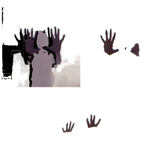
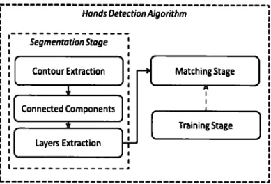
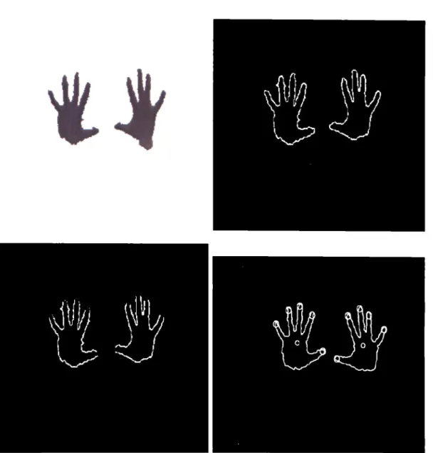
(27) are out of range Runye('fllu:rval'Ue - l). In this work, the user can manually modify constant L lo suit a specific apµlication. This tedmique fur <letecting han<ls is very simple and fast but has severa) lirnitations. The most notorious is that both user'hands have to be in the same coordinate in z. If two users wants to utilize our systern, it is even more difficult that both hands of both users are in the sarne coordinate in z. In Figure 4.l(a) we can see the limitations of this approach. Also it is irnportant to rnention the definitive algorithrn has two version, a GPU version anda CPU version. The CPU version runs about 8 FPS and the GPU version at 25 FPS. The speed up was substantial and it was achieved because several algorithrns were coded in CUDA. In the appendix section can be found CUDA kernels for de segrnentation step, a universal filter, and a morphological closing. Now we will explain the definitive technique for detecting hands.. Hands Detection Algorithm Segmentation Stage Contour Extraction. Matching Stage. Connected Components. [. Layers Extraction. Training Stage. ]. ----------------~. L-------------------------------------------~ Figure 4.2: Hand Detection Algorithm Flowchart. The algorithrn has three rnain stages, training, segmentation and rnatching stages Figure 4.2. In the training stage, scenes containing users are manually segrnented. This segrnentation is aimed to eliminate all pixels except those belonging to pedestrians' hands. Then the most significant eigen values of hands' blobs are saved and a generic hand rnodel is leamed from this data. The Segmentation stage is intended to separate pedestrians into depth layers. In Figure 4.3(a) we can see a pedestrian correctly separated in two layers, one for the hands and anothcr for thc rcst of thc body. Laycrs that are not covcrcd by othcrs are rnarked as likely hands. In the rnatching stage a correlation rnetric is calculated between likely hands and the previously learned hand models. Depending on the outcome of this match, layers 22.
(28) ... (. l.. I Figure 4.3: Hand Detection Outcomes. 23.
(29) are recognized either as a hand or not. Details are described below. Our hand rnodel is sirnplistic with the purpose of avoiding detection mistakes caused by variety in hands' look and pose. The matching stage is also benefitted because its computational costs are minimized. Our hand is rnodelled as a rectangle with an aspect ratio of about 1.4 and eigen values between meanH ead - ST D and meanH ead + ST D pixels. In the Contour Extraction step, we take a depth map from a scene and compute the absolute depth derivative in X and Y axes using a 9x9 pixel window. This outcome is then compared to a fixed threshold in arder to binarize the image. The outcome of the Contour Extraction step is an image where black pixels represent abrupt changes in depth and white pixels represent fiat regions (Figure 4.3(a) ). It is important to notice depth derivatives separate the pedestrians' body into severa! blobs. Usually these blobs correspond to hands' blobs, and body's blobs. A correct blob scparation depends on the threshold binarizing derivative images. Regardless of the position and separation from the camera, the derivative profile is mostly invariant, therefore, once a correct binarization threshold is found it works far all depth conditions. The Connected Component step applies a labeling algorithm to the Contour Extraction outcome. It is aimed to extract blob's features. The features we consider important are: width (blobW), height (blobH), aspect ratio (aspectR), and dcpth value which correspond to the closest pixel to camera (blobMinVal). This value is extracted from the original depth map. The Layer Extraction step is used to paint a layer far each blob found in the previous process. Put simply, we use blobs' features to create rectangles of size blobW + dilatenxblobH + dilaten and an intensity level of blobM in V al. The Dilating of layers by the Dilaten assurcs thc laycr corrcsponding to body will be covered by hand layers, dilaten is fixed to 10% of meanH ead. Therefore, the Layers Extraction stage is aimed to determine which layers are covered by other and which are not. It is important to know this feature because the only layers which correspond to hands are those that are not covered by others. This step adds a feature to each of the blobs which reports if a blob is covered (isCovered = 1) or not (isCovered = O). In thc Matching Stagc, it is dctermined if a layer is a hand or not based on fcatures: blobW, blobH, aspectR and isCovered. All blobs with a value isCovered = 1 are discarded. If a rernaining blob is similar in size and aspect ratio to the learned model in the Training Step it is marked as a hand. Figure 4.3(a) illustrates examples where correct hand detectiou has beeu achieved.. 24.
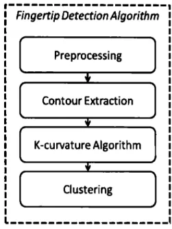
(30) 4.3. Fingertip Detection System Description. Fingertip Detection Algorithm Preprocessing. • Contour Extraction. • K-curvature Algorithm. • Clustering. Figure 4.4: Fingertips Detection Algorithm Flowchart. The algorithm has four rnain stages, preprocessing,contour extraction, k-curvature algorithm and clustering Figure4.4. Below we'll explain in detail all these stages: In the Preprocessing stage a simple Gaussian filter is used to reduce camera noise and isolated pixels that are not part of the object of interest. Then morphological close filtering is perforrned on the resultiug image to fill the gaps and smooth outer edges (Figure 4.5( a)). In thc contour cxtraction stagc, all contours are cxtractcd using OpenCV's implementation of Approximate Freeman Chains [28] (Figure 4.5(a)) . For the following steps we used only those contours larger than a given threshold, experimentally obtained, avoiding processing contours that are not part of the object of interest. For several applications, it is useful to know the hand's centroid (Figure 4.5(a)) in order to track their position. From the previous step we know the hands blob contour. To compute their centroid, it is easy to calculate Hu moments [16] for each contour with thc following formula:. A =muo , X =. 1n1,o. e. A. Y _ e -. =. 11ti,o. mo,1 _. moa mo:1 mo,o. A. -. where (xc, ye) is the center of gravity of the object. Then the K-curvature method is used. We choose this algorithm because of its speed and accuracy, we also chose. 25.
(31) Figure 4.5: Fingertip Detection Outcomes. 26.
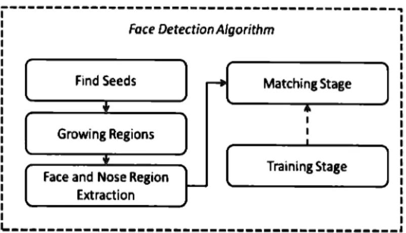
(32) this algorithm for detecting fingertips. Its only disadvantage is the definition of the k constant. To sol ve this problern we defined a "general" k that works well in the 3.5 m range that our depth sensor can handle. General k gets about 10 to 20 points that belong to fingertips instead of one per fingertip. We can see results of this step in Figure 4.5(a). The Clustering stage consists in getting the actual 3D coordinate for each fingertip. To perform this we need to cluster the dots obtained in previous step. To achieve our goal while maintaining the speed of the fingertip <letection algorithm we implemented a modified version of k-rneans for the performance of this task. The main idea of this algorithrn is the use of the k-means algorithm for centering the centers that the AS algorithm computed, as needed based on a given radius threshold. In following lines we show the pseudo-code for this algorithm: / / Repeat until threshold is accomplished while continue / / Compute k-means algorithm DataCenters = kMean( centers, data, thresholdK) // Compute AS algorithm [newCenters] = as(DataCenters, thresholdAS) / / Check if we have new centers if newCenters == centers continuar = O break end end Hand Detection and Fingertip Detection algorithms were designed so they had no problem detecting the hands and fingertips of multiple users.. 4.4. Face Detection System Description. It is composed by 3 stages 4.6. For this stage we assume the nose is the closest point to the camera and the forehead of person's face is above his nose. The main idea in this stcp is scgmcnting thc pcrson's facc into parts. Thcsc parts corrcspond to nose and the rest of the face. This segmentation is performed by seeding a growing region algorithm with the closest point to camera (nose_region) and a point x pixels above it (! orehead_region). To accelerate computation, we coded the growing region algorithm in CUDA. In arder to avoid the merging of nose_region and Jorehead_region a. 27.
(33) Face DetectionA/gorithm. Find Seeds. Matching Stage. Growing Regions. [. Face and Nose Region Extraction. Training Stage. ]. ~------------------------------------------Figure 4.6: Face Detection Algorithm Flowchart. dcrivativc is applicd to thc dcpth map. Once nose_region and f orehead_region have been found, we build a layer for each region in the same way we did in the Hand Detection Stage. The last step is a Matching Stage that is the same as the Hand Detection Stage. Although this proposed method for detecting faces is not as general as the ones presented in previously mentioned articles, our algorithm is faster and simpler. So it suits better our requirements. In Figure 4.7(a) we can see the outcome for each step in this stage.. 4.5. Experimental Results for Hand, Fingertip and Face Detection. The proposed detection algorithms are implemented using C-CUDA and real time has been achieved on a personal computer.In arder to evaluate the accuracy of the detection algorithms we conducted experiments in an indoor scenario. We asked 4 persons to test our algorithms and we achieve a detectionrate of 95.17% and a f alsealarm of 3.22% on 200 framcs.. It is difficult to compare our method to others because there are not a standard for evaluating this kind of applications. The only thing we can say about our method is the next:. • It is more robust than rnethods that use RGB cameras because ours is inscnsitive. 28.
(34) (a) (1): Original Dcpth Imagc. (2): Dcrivativc Stcp. In Red are Markcd Secd Points. (.'1): Forehea<l Regio11. (4): '.'Jose llegio11.. Figure 4. 7: Facc Dctcction Outcomcs. 29.
(35) to shadows and illumination changes • It is more robust comparc<l to mcthod that nccds to scc thc facc of thc uscrs • It has been implemented in CUDA and runs at 25 FPS. 30.
(36) Chapter 5. Conclusions and Future Work. Our goals were achieved. This paper presented a real time pedestrian recognition system using depth maps information. Our technique can detect pedestrians in dense crowds and a high detection rate has been achieved. Also we presented a real time hand, fingertip and face detection system using depth map informatiou. Our technique can detect hands, fingertips and faces in real time and it is insensitive to lighting conditions, reflection and shadows. For both systems using depth derivative was a key component. Thcy has bccn implcmcntcd using C-CUDA so dcpth maps of highcr rcsolution can be used without losing much performance. In future work we will develop a binocular system to substitute our low cost depth camera. Thereby allowing our system to be tested outdoors with a greater field of view. Also we will unify the separate systems and try it in different applications.. 31.
(37) Appendix A. Growing Region CUDA Kernel __ global __ void firstpassKernel(unsigned char• resultData, unaigned char• derivativeData, unaigned char• voightedData, un1ignad int iaagoHoight, un1ignod int imagoWidth) {. unaignad int col • __mul24(blockldx.I, blockDim.•) + threadld:1.:1¡ unsigned int row • __ mul24(blockldi .y ,block.Dim.y) + tbreadld..J. .y¡ uneigned ia.t inde•1Ch • __aul24(row , iaageWidtb) + col¡ 1f ((col >• 0).U:(col < i.mag•Width).U:(rov >• O).U:(rov < iugoHoight)) { rosultData[indozlCh) • derivativoData[indozlCh); voightodData[indozlCh) • O; }. __ global __ void growingKernel(unaigned cbu-• eourceData, u.n.aign.ad char• reeultData, unsigned cbar• eeed.Data, u.o.signad cbar• newNeighborsData, unsigned cha.r• weighted.Data, uneigned int i.u.geHeigbt, unsigned int imageWidth, int threabold, int• flag, int counter) {. unaignod int col = __ mul24(blockld.lt. •, blockDim. •J + throadld.lt. •; unsignod int rov • __ mul24 (blockld.lt. y, blockD1m. y) + throadld.lt. y; unaignod int inde<lCh • __ mul24 (rov , imageWidth) + col; WU1igned unoigned uneignad unoignad int dif;. int. int int int. neighl; naigh2; naighJ; naigh4;. if((col >• O).U:(col < i.mageWidth).U:(rov >• O).U:(rov < iaagoHeight)) {. if ( counter •• O) {. neighl neigh2 neigh3 neigh4. • • • •. imagoWidth) + col - 1) reaultData(__aul24(rov reaultDataL_aul24(rov + 1, imageWidth) + col ) i11ageWidth) + col + 1) reaultDataL_aul24(row reaultDataL_aul24(row - 1, imagoWidth) + col ). ; ; ; ;. it ((naighl •• 255) 11(neigh2 •• 255) 11(neigh3 •• 266) 11 (neigh4 •• 266)) {. if (neighl •• 255) n•wNeighboraData[inde.z.lCh] • aourcaOataL_mul24(row , imag•Widtb) + col - l] ¡ if (neigh2 •• 255) newNeighboraData[indHlCh) • sourceData(__mul24(row + 1, imageWidth) + col ) ; it (neigh3 •• 266) nevNeighborsData[indulCh) • sourceDataL_mul24(rov , 1mageWidth) + col + 1);. if(neigh4 •• 266) ne11Neighbor1Data[inde.z.1Ch] • 1ourceOata [__mul24(row - 1, iaageWidth) + col];. 32.
(38) elae oovNoighboreData[indHlCb]. • O;. __ ayoctbreada O ;. if(newNeighboraData[iodulCb] > O) {. dif • (iot) ((1ot)aourceData[iodu1Cb] - (iot)oewNeigbboroDeta[indHlCb]);. it((dif < tbreebold)ü(dif > -tbreabold)) {. rHultData[iodez!Cb] • 256; oowNoighboraData[iodHlCb] • aourcoData[iodHlCb]; if(woightodData[iodezlCb] > O) {. if(veightedData[ioclulCb] > sourceData[iodulCb]) { voigbtedData[iodez!Cb] • aourceData [iodez!Cb] ; }. •l•• veightedData[iodulCb] • aourceData[indezlCb];. •l•• reaultData[iodezlCb] • O; oovNeighboraData[iodeslCb] • O; veigbtadData[ioclulCb] • O; } }. •l•• oeighl ne1gb2 neigh3 ooigb4. • • • •. reoultData (__aul24 (rov , imageWidtb) • col - 1] reoultData (__aul24 (rov • 1, imagoWidtb) • col ] imagoWidtb) • col • 1] reeultDataL_•u124(rov reeultData(__aul24(rov - 1, imagoWidtb) • col ]. 1f ((oeigbl •• 265) {. ; ; ; ;. 11 (oe1gb2 •• 265) 11(ne1gb3 •• 255) 11 (oe1gb4 •• 265)). 1f (ooighl •• 266) oovNoigbboroData[indHlCb] • oovNeigbboraDataL_11ul24(row , 1magoW1dtb) • col - 1]; 1f (oo1gh2 •• 266) oevNoigbboroData[lndulCb] • oewNo1gbboroDataL_aul24(row • 1, 1magoW1dtb) • col. J;. if (ooigb3 •• 255) oowNoighboraData[lndaslCb] • oevNeighboroDataL_aul24(rov , imageWidtb) • col • 1]; 1f (oeigb4 •• 256) newNeigbboraData[indezlCb] • newNeigbbor1Data.L_mul24(rov - 1, iaageWidtb) ... col]¡. elae oowNoighboroData [iodoslCb]. • O;. __ oyoctbroadll O ;. 1f(oewNo1ghboraData[iodo•1Cb] > O) {. dif • (iot) ((1ot)oourceData[1odH1Cb] - (iot)oovNeigbboraData[iodeslCb]);. U((dif < tbreebold)ü(dif > -tbreabold)) {. reaultData[iodoslCb] • 255; it(woightedData[ioclulCb] > O) { 1f (woightodData [ioclHlCb] > oevNeighboreData [iodo&ICb]) {. voighteclData[ioclHlCh) • nowNolghboroData[iodeslCb); }. 33.
(39) .1 •• weightedData[inclHlCb] • nowNeighborsData[indealCb];. ,1 •• roaultData[inclozlCh] • O; 111wNoighboroData[inclozlCb] • O; DIWNoighboroData[inclHlCb] • O; } }. }. void rogion_growing_GPU_III (unoignod char •eourco, unaignod char •roault, WU1iped char• derivativa. U1U1iped chu• weightedRaault, unaignod int illllg1H1ight, unaignod int i.ugoWidth, int rog_•udiot, unaignod int illllg1Sizo) {. dim3 blocll(16, 16, 1); dim3 grid(iaagollidtb / blocll.s, imageHeight / block.y, 1); iDU flag_b; int• flag_d; int• bounda_b;. unaignod char• nowNeighboraData_d; flag_h • (int>)lllllloc(l • eizeof(int)); boundo_b • (int•)11alloc(266 • 2 • aizeof(int)); initkrayCuda( (voidu)tflag_d, (unsigned int)(I • aizoof(int)), "flag_d"); initkrayCuda( (voidu).tnewNoighboroData_d, (un1ign1d i11t)i11ag1Size, '111w noighboro data');. flag_b [O] • 1; int coUDter • O;. //firat pu•, re•ultData • eeed( derivative ) firatpuaKernel<<<grid blocll>>>(reault, darivative, weigbtedR.e1ult, 1•ageHeigh.t, i•ageWidth): 1. wbilo((flag_h[O) •• l)ü(countar < 100)) {. growingl(emel<<<grid block>>>(eource, reault, derivativa, newlleighboraData_d, weightedReeult, illllg1H11ght, iugeWidth, rog_mudiet, flag_d, counter); 1. //printf('\n aftor Xd', flag_h[O)); counter++ :. frodrrayCuda( tflag_d ) ; fredrrayCuda( bewNeighboraData_d ) : fr11ArrayCuda( tflag_d ) ;. 34.
(40) Appendix B. Segmentation by Depth CUDAKernel lia.clude. 11. fwictionaCUDA. cuh 11. __global__ void •1nValue(unoignod char• dapthPuelo, unaigned int 1. .gellidth, 111U1igned int imageHeight, unaigned chu• partialMinval_davica , unaignad int nualllocko) { __ aharad __ unaignad char cacha (600) ; WU1ignod int tid • blockld.K. I • blockllia. I + threadld.K. I; 111U1igned int cacholDdH • thraadld.K. I; if(depthPiHls[tid) < 40) depthP1Hla[t1d) • 266; __ ayncthraada O ;. 1f (tid < iugallidth • imagaHaight) cacha [cachalndH) • dapthPbelo [tid); __ ayncthraada O ;. int 1 • blockllill. z/2;. while( 1 •• O){ if(cachelDdH < i){ unaignad char tupHin • partialHinval_devica[cachalndH + 1); 1f(tupH1n •• O) tupHiD • 266 ; 1f ((tupHin < cache[cachelndH))ü(tompHin •· O)) cache[cachelndH] • tupHin;. __ ayncthreada O ; /• 2;. 1f (cachalndH •• O){ partialHinval_davica [blockld.K. z) • cacha [O) ; }. __ ayncthreada O ; }. __ global__ void imageSepantation(unaigned chu• dapthPbela, unaigned int iaagallidth, unaignad int iaagaHaight, unaigned char ainval){ 111U1ipad int id • blockld.K. I. •. blockllim. I + thraadld.K. I;. 35.
(41) U (id >• l.mag•llidtb • imagoHoight) return¡. U((depthPixels[id) < (mtnval - 12)) 11 (depthPixels[id) > (ainval • 22))) depthPiHle [id) • 255;. void oeputationlltlptb(unaipod cbar• depthPiiels, unaipd int iugollidtb, unaipod int imag•H•ight){ •:rt•rn 1111sipod int nudlocks; o:rtorn unaipod int n1111Throada; unaipod cbar •inv; unaiped cbar •partialHinval_device; unaipd cbar •partialHinval_boat;. nudlocu • O; nuaThreadli • O¡ c . .putoCridSize(iaagoWidtb • iaagoHoigbt, 512, nllllllllocko, numThroada); //ata.val array partialHinval_hoot • (unaipad char•)•alloc(600 • 1izoof(unaipod cbar)); cuclallalloc((void.. ).tpartialHinval_dovice, 600 • 1izeot (unaigned char)); aia.Valuo<«nudlocka, n1111Threada»> (depthPilela, imageWidth, iugoHoight, partialMinval_device, 600); 11 cudaThroadSynchronizo () ; cuciall•cpy (partialMinval_host, partialHinval_dovico, 600 • aizoof(11111ignod char), cuclallucpyDevicoToHo1t); unaipod char to•pHin • partialHtnval_hoot [O) ; tor(int i • O; 1 < nualllocko; i .. ){ //printf ( •\n partialMinval_hoat [i] : ld", partialMinval_host [i)) ; it(tupHin •• O) tupMin • 255 ; U((partialHinval_hoat[i) < tupM1n)ü(teapMin !• O)) tmpffin • partialMinval_hoat [i) ; }. //printf ( • \n ain: :4cl • , tupMin) ;. i-eSepentation<<<nuaBloclla DW1Thread11>>> (depthP11:el11. iaagollidtb, iaag•Height, tupMin); I. tro1lrrayCuda( partialMinval_dovico ) ; tro•(partialMinval_hoat); }. 36.
(42) Appendix C. Universal Filter CUDA Kernel 11.nclude <atdio. b> lin.clude •tunctionaCUDA. cub• ldefin• blockSize 8;. __¡lobal __ void co11volutio11GPU(unaigned char• sourcePisela, unaiped char• dHtinyPiala, unaigned int i11ageHeigbt, unaigned int i.mageWidtb, unaigned int nCbannela, float• kernel, int radiw,Kernal, int aizeKernel){. unaigned int col • __11ul24(blocllldlt.z, blockDi11.z) + tbreadldlt.z; Wlllipod int row • __.ul24(blockldlt.y,blockDi11.y) + tbreadldlt.y; Wllliped int indei • __11ul24(row , iaageWidtb) + col;. float value; float aum¡. value • O.O¡ 1ua • O.O¡. __ oyoctbreada O ;. 1f ((indu <• (__aul24(111a¡eHeigbt , ima¡oWidtb) ))ü(col > radiuaKernol + 1) ü(col < ima¡eWidtb - (radiuaKernel + !))ü (row > radiuaKernel • 1) ü(row < iaageHeigbt - (radiuaKernel + !))){. forUnt. • - rad.iuaKarnel;. <• radiusKernal; i++)//row. • - radiuaKernal;. <• radiuaKernel; j++J//col. {. for(int {. value • aourcePhela[(__aul24((row • 1) , iaageWidtb) + (col • j))); oua. • oua + v&lue • kernel (__aul24( (1 + radiw,Kernel), aizeKernel) + (j + radiw,Kernel)];. daatinyPhela[indH] • aum;. int buildKernel(float •kernel, in.t aizeKernel, conat char •na.me){ int rad.iuaKernel • (aiz1Kern1l - l) / 2;. 37.
(43) if(naa• ••. •••an.. tor(int 1 • O: tor(int J • O;. 11. ). < aizeK•rnel¡ i"++){ < oizeKornol: j++ ){. kornol[i • oizeKernel + j] • l. O / (oizeKernel • oizoKornol): //printt('\n kor Xt', kornol[i • eizeKernal + j)):. if (n.u• •• •a:au••ian•) {. int kernelvaluH[81) • {O, O, 1, 1, 1, 1, 1, O, O, O, 1, 2, 3, 3, 3, 2, 1, 1, 2, 3, 6, 7, 6, 3, 2, 1, 1, 3, 6, 9, 11, 9, 6, 3, 1, 1, 3, 7, 11, 12, 11, 7, 3, 1, 1, 3, 6, 9, 11, 9, 6, 3, 1, 1, 2, 3, 6, 7, 6, 3, 2, 1, O, 1, 2, 3, 3, 3, 2, 1, O, O, O, 1, 1, 1, 1, 1, O, O};. º·. int aum¡ 1t (lizeKornel •• 3) ... • 92¡. eloe 1t (lizeKernel •• 5) ... • 180; oloe 1t (aizeKonuil •• 7) .... • 236; elH 1t (aizeKernel •• 9) .... • 266;. •l••. printf(•\n •rror Kernel aize•);. for(int 1 • -radiuaKernel ; 1 <• radiusKernel ¡ 1+-t) {. tor(int J • -radiuaKornel; j <• radiuaKornel; J++) {. kernel[ (1 + radiueKornol) • eizeKernel + (J + radiuoKornol)) • (float)(kernolvalues[(4 + 1) • 9 + (4 + J)))/a1111: } }. uc........ ••) {. return racUuaKernel;. void perforaF1lter1Cb(u.naiped cbar• eourcePixela, W18iped cbar• deatinyPixela, unoiped int iugeHoight, 11Dliped int iaagoWidth,. WU1iped int nChannela, conat char •n.1111.e, in.t eizeKernel){. it(oizeKernel > 11) {. printt("\n Mu kernel oize io 11'): return¡. 38.
(44) float •kernel¡ int radiusKernel; kernel • (float•)aalloc( aizeKernel • aizeKernel • sizeof(float)) ¡ 1f (kenel •• IIULL) printf ( •kernel aalloc error•) ;. radiu1Kernel • buildKernel (kernel I aizeKernel, naae) ;. float •lr.ernel ... d¡ cudaHalloc ( (void•• )tkernel ...d.. aizeKernel•sizeKernel• aizeof (f loat)) ;. cuciaH•cpy(llonol_d, kenel, eizeKenel•aizeKonol • 1izoof(float), cuciaHemcpyHoatToDevice);. dial blocll(B, e, 1); d1113 grid(i•ageWidth / block.•, iugeHeigbt / block.y, 1): convolutionGPU«<grid, block»> (oourcePiula, de1tinyPüelo, i•ag•Height, i•ageWidth, nChannel1, kern.el ... d, radiusKernel, aizeKernel) ¡ froo(kernel);. 39.
(45) Bibliography. [1] Jun Rekimoto Adiyan Ylujibiya, Takashi Miyaki. Anywhere touchtyping: Text input on arbitrary surface using depth sensing. UIST '1 O Adjunct proceedings of the 23nd annual A CM symposium on User interface software and technology, 2010. [2] Byeong Doo Ahn and H. Ko. Pose-invariant face recognition using cylindrical model and stereo camera. Proceedings of 2004 lnternational Symposium on lntelligent Signal Processing and Communication Systems, 2004. [3] H. Ando, H. Fujiyoshi. Humau-area segmeutation by selectiug similar silhouette images based on weak-classifier response. 20th lnternational Conference on Pattern Recognition, 2010. [4] Arnaud Bcrnard and Bcnny Bing. Automatic hand rcfcrcncc acquisition using a stereo 3d webcam. Proceedings of the Fourth ACM/IEEE lnternational Conference on Distributed Smart Cameras, 2010. [5] Rob Byrd and RanjaniBalaji. Real time 2-d face detection using color ratios and k-mean clustering. Proceedings of the 44th annual Southeast regional conference, 2006. [6] J. M. Armingol C. Hilario, J. M. Collado and A. de la Escalera. Pedestrian detcction for intclligcnt vchiclcs bascd on active contour modcls and stcrco vision. Proceedings of the IEEE lntelligent Vehicular Sytems, 2005. [7] M. Baris Caglar and Niels Lobo. Open hand detection in a cluttered single image using finger primitives. Proceedings of the 2006 Conference on Computer Vision and Pattern Recognition Workshop {CVPRW06}, 2006. [8] Ekambaram Rajmadhan Chern-Horng Sim and Surendra Ranganath. Using color bin images for crowd detections. 15th IEEE lnternational Conference on lmage Processing, 2008. [9] Hrvoje Benko Chris Harrison and Andrew D. Wilson. Omnitouch: Wearable multitouch interaction everywhere. Proceedings of the 24th annual ACM symposium on User interface software and technology, 2011.. 40.
(46) [10] Michael Van den Bergh and Luc Van Gool. Cornbining rgb and tof cameras for real-time 3d hand gesture interaction. 2011 IEEE Workshop on Applications of Comp'Uter Vis'ion (WACV), 2011.. [11] Thien Cong Pharn Dung Duc ~guyen and Jae Wook Jeon. Fingertip detection with morphology and geometric calculation. The 2009 IEEE/RSJ lnternational Conference on Intelligent Robots and Systems, 2009. [12] Salih Burak GÁ1ktAirk and Carlo Toma.si. 3d head tracking based on recognition and interpolation using a time-of-flight depth sensor. IEEE Computer Society Con/erence on Computer Vision and Pattern Recognition, 2004. [13] Benko H. Harrison, C. and Wilson. Omnitouch: Wearable multitouch interaction everywhere. In Proceedings of the 24th Annual ACM Symposium on User interface Software and Technology, 2011. [14] Shibahara T. Ito K. Aoki T. Nakajima H. Hayasaka, A. and K. Kobayashi. A 3d face recognition system using passive stereo vision and its performance evaluation. ISPACS '06. International Symposium on Intelligent Signa[ Processing and Communications, 2006. [15] Gregorij Kurillo Hee-Sung Kim and Ruzena Bajcsy. Hand tracking and motion detection from the sequence of stereo color image frames. IEEE International Conference on Industrial Teclmology, 2008. [16] M. K. Hu. Visual pattern recog11itio11 by momeut i11varia11ts. /RE Trans. lnform. Theory, 1962. [17] Sergiu ~edevschi Ion Giosan and Silviu Bota. Real time stereo vision based pedestrian dctcction using full body contours. IEEE 5th International Conference on lntelligent Computer Communication and Processing, 2009. [18] Liwei Chen Jian Wei, Shigang Wang and Tianxiao Cuan. Adaptive stereo video object segmentation based on depth and spatio-temporal information. World Congress on Computer Science and lnformation Engineering, 2009. [19] Haoxing Wang Jungme Park, Yun Luo and Yi L. Murphey. Pedestrian detection by modeling local convex shape features. 19th International Conference on Pattern Recognition, 2008.. [20] Jason Oberg andRyan Kastner Junguk Cho, Shahnam Mirzaei. Fpga-based face dctcction systcm using haar classifiers. Proceeding of the ACM/SIGDA international symposium on Field programmable gate arrays, 2009.. 41.
(47) [21] M. Kolsch and :vi. Turk. Robust hand detection. In Pruc. /ntl. Conf. Face and Gesture Recognilion, 2004. [22] Byungsung Lee and Junchul Chun. Manipulation of virtual objects in marker-less ar system by fingertip tracking and hand gesture recognition. !GIS '09, 2009.. [23] Byungsung Lee and Junchul Chun. Manipulation of virtual objects in marker-less ar system by fiugertip tracking and hand gesture recognition. !GIS '09 Proceed-. ings of the 2nd lnternational Con/eren ce on lnteraction Sciences: In/ormation Technology, Culture and Human, 2009. [24] S. Z. Li and A. K. Jai11. Handbook offace recognition. Springer, 2005. [25] Gregory Baratoff Martin Rapus, Stefan Munder and Joachim Denzler. Pedestrian recognition using comhined low-resolution depth and intensity images. IEEE lntelligent Vehicles Syrnposiurn, 2008. [26] Noel E. OConnor Philip Kelly and Alan F. Smeaton. Pedestrian detection in uncontrolled environmeuts using stereo and biometric information. Proceedings of. the 4th ACM international workshop on Video surveillance and sensor networks, 2006.. [27] Momoh Jimoh El Salami Amir A. Shafie S. Bilal, Rini Akmeliawati and El Mehdi Bouhabba. A hybrid method using haar-like and skin-color algorithm for hand posture detection, recognition and tracking. Proceedings of the 201 O IEEE lnternational Conference on Mechatronics and Automation, 2010.. [28] ~aotoshi Seo. Tutorial: Opencv haartraining (rapid object detection with a cascade of l>oosted classifiers based on haar-like features). http://note.sonots.com/SciSoftware/haartraining.html, 2008. [29] Annah Roh Sung-il Kaug and Hyunki Hong. Using depth and skin color for hand gesture classification. 2011 IEEE lnternational Conference on Consumer Electronics (ICCE), 2011.. [30] Nguyen Dang Binh Thuy Thi Nguyen and Horst Bischof. An active boostingbascd lcarning [rarncwork for real-time hand dctcction. Bth IEEE International Conference on A utornatic Face and Gesture Recognition, 2008.. [31] Shopper Tracker. Shopper tracker. http://www.agileroute.com/shoppertracker/, 2011.. [32] Thiago R. Trigo and Sergio Roberto M. Pellegrino. An analysis of featurrd for hand-gesture classification. 17th lnternational Con/eren ce on Systems, Signals and Image Processing, 2010.. 42.
(48) [33] Duan-Li Liao \Vt•11-Hu11g Ting, Chia-Chang Li a11d Hian-Ku11 Tenn. Digital content rnanipulati11g syslem using han<l gesture. 2011 Internatfonal Conference on Electrical and Control Engineering {ICECE), 2011. [34] et al. William T. Freeman, David B. Anderson. Computer vision for interactive computer graphics. IEEE Computer Graphics and Applications. Volume 18, Number 3, 1998. [35] Fengliang Xu and Kikuo Fujimura. Human detection using depth and gray images. Proceedings of the IEEE Conference on Advanced Video and Signal Based Surveillance, 2003. [36] S. Worrall Y. Ma and A. M. Kondoz. Depth assisted visual tracking. lOth Workshop on lmage Analysis for Multimedia lnteractive Services, 2009. [37] S. Worrall Y. Ma and A.M. Kondoz. Automatic video object segmentation using depth information aud an active contour model. IEEE lOth Workshop on Multimedia Signa[ Processing, 2008. [38] Liu Yun and Zhang Peng. An automatic hand gesture recognition system based on viola-joncs mcthod and svms. 2009 Second lnternational Workshop on Computer Science and Engineering, 2009. [39] Chengbin Zeng and Huadong Ma. Robust head-shoulder detection by pca-based multilevel hog-lLp detector for people counting. 20th lnte1·national Conference on Pattern Recognition {ICPR), 2010.. 43.
(49)
Figure
+7
Documento similar
In our proposal, a pre-trained CenterNet HourGlass104 Key- points (CHK) detection model is used to identify people bounding boxes and keypoints to achieve the automatic labelling of
In our approach, we retain the idea of using both mathematical programming and fuzzy membership to detect overlapping communities, but we replace the fuzzy objective function
O BJECTIVE AND APPROACH In this work, our main concern is to provide a stability and error analysis of high-order CFQM exponential integrators for the time integration of
As this is the first attempt at using human experi- ence to control an agent in the Robosoccer domain, we have chosen to imitate the human player in low-level actions like
There is an important body of literature using multi-criteria distance function methods for the aggregation of a battery of sustainability indicators in order to obtain a
In the edition where the SPOC materials were available, we have observed a correlation between the students’ final marks and their percentage rate of
all our experiments on the 151 latent and tenprint minutiae set to establish the importance of rare minutiae using our proposed algorithm in improving the rank identification
Our objective in this paper is to propose a novel framework for map comparison that is based on the use of symbolic entropy to detect spatial patterns in thematic maps (Ruiz et al
